Table of Contents
Advertisement
Available languages
Available languages
Quick Links
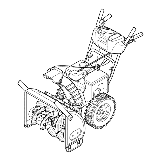
Operator's Manual
30" SNOW THROWER
Model No. 247.888301
CAUTION: Before using
this product, read this
manual and follow all
safety rules and operating
instructions.
Sears Brands Management Corporation, Hoffman Estates, IL 60179, U.S.A.
Visit our website: www.craftsman.com
• SAFETY
• ASSEMBLY
• OPERATION
• MAINTENANCE
• PARTS LIST
• ESPAÑOL
FORM NO. 769-05137E
7/26/2011
Advertisement
Chapters
Table of Contents

Related Manuals for Craftsman 247.888301


Summary of Contents for Craftsman 247.888301
- Page 1 Operator’s Manual 30” SNOW THROWER Model No. 247.888301 • SAFETY • ASSEMBLY • OPERATION • MAINTENANCE • PARTS LIST CAUTION: Before using • ESPAÑOL this product, read this manual and follow all safety rules and operating instructions. Sears Brands Management Corporation, Hoffman Estates, IL 60179, U.S.A.
-
Page 2: Table Of Contents
This warranty applies for only one year from the date of purchase if this product is ever used while providing commercial services or if rented to another person. For warranty coverage details to obtain repair or replacement, visit the web site: www.craftsman.com This warranty covers ONLY defects in material and workmanship. Warranty coverage does not include: •... -
Page 3: Safe Operation Practices
SAFETY INSTRUCTIONS WARNING DANGER This machine was built to be operated according to the safe opera- This symbol points out important safety instructions which, if not tion practices in this manual. As with any type of power equipment, followed, could endanger the personal safety and/or property of carelessness or error on the part of the operator can result in serious yourself and others. - Page 4 SAFETY INSTRUCTIONS Safe Handling of Gasoline • Exercise extreme caution when operating on or crossing gravel surfaces. Stay alert for hidden hazards or traffic. To avoid personal injury or property damage use extreme care in handling gasoline. Gasoline is extremely flammable and the vapors are •...
- Page 5 SAFETY INSTRUCTIONS MAINTENANCE & STORAGE DO NOT MODIFY ENGINE • Never tamper with safety devices. Check their proper operation To avoid serious injury or death, do not modify engine in any way. regularly. Refer to the maintenance and adjustment sections of Tampering with the governor setting can lead to a runaway engine and this manual.
- Page 6 SAFETY INSTRUCTIONS SAFETY SYMBOLS This page depicts and describes safety symbols that may appear on this product. Read, understand, and follow all instructions on the machine before attempting to assemble and operate. Symbol Description READ THE OPERATOR’S MANUAL(S) Read, understand, and follow all instructions in the manual(s) before attempting to assemble and operate WARNING—...
- Page 7 This page left intentionally blank.
-
Page 8: Assembly
ASSEMBLY NOTE: References to right or left side of the snow thrower are determined from behind the unit in the operating position (standing directly behind the snow thrower, facing the handle panel). Chute Control Head REMOVING FROM CARTON Cut the corners of the carton and lay the sides flat on the ground. Chute Support Remove and discard all packing inserts. - Page 9 ASSEMBLY Place chute onto chute base and ensure chute control rod is Chute Control positioned under handle panel. Install hex bolt previously removed Top View Input but do not secure with wing nut at this time. See Figure 4. Squeeze the trigger on the handle panel joystick and rotate the chute by hand to face forward.
- Page 10 ASSEMBLY 7. Make sure all cables are routed to the left of the chute control rod. Line up the hole in the chute control rod with the arrow on the input shaft and insert the rod into the input shaft below joystick on handle panel.
- Page 11 ASSEMBLY 10. Check that all cables are properly routed through the cable guide on the engine. See Figure 10. NOTE: If the chute control is not assembled correctly it will not move freely nor will it move fully to the right and left. 11.
- Page 12 ASSEMBLY Chute Clean-Out Tool A chute clean-out tool is fastened to the top of the auger housing with a mounting clip. See Figure 12. The tool is designed to clear a chute assembly of ice and snow. This item is fastened with a cable tie at the factory.
- Page 13 ASSEMBLY • Use a middle or lower position when the area to be cleared is uneven, such as a gravel driveway. NOTE: If you choose to operate the snow thrower on a gravel surface, keep the skid shoes in position for maximum clearance between the ground and the shave plate.
-
Page 14: Operation
Engine oil level can be checked and oil added through the oil fill. falling into the augers for throwing. Meets ANSI Safety Standards Craftsman Snow Throwers conform to the safety standard of the American National Standards Institute (ANSI). - Page 15 OPERATION THROTTLE CONTROL The auger control is located on the left handle. Squeeze the control grip against the handle to engage the auger and start snow throwing action. Release to stop. DRIVE CONTROL/ AUGER CONTROL LOCK The throttle control is located on the rear of the engine. It regulates the DRIVE speed of the engine and will shut off the engine when moved into the CONTROL...
- Page 16 OPERATION CLEAN-OUT TOOL • Refuel in a well-ventilated area with the engine stopped. Do not smoke or allow flames or sparks in the area where the engine is WARNING refueled or where gasoline is stored. • Do not overfill the fuel tank. After refueling, make sure the tank Never use your hands to clear a clogged chute assembly.
- Page 17 OPERATION TO ENGAGE DRIVE Move throttle control to FAST (rabbit) position. With the throttle control in the Fast (rabbit) position, move shift Move choke to the CHOKE position (cold engine start). If lever into one of the six forward (F) positions or two reverse (R) engine is warm, place choke in RUN position.
-
Page 18: Service &Maintenance
SERVICE AND MAINTENANCE MAINTENANCE SCHEDULE WARNING Before performing any type of maintenance/service, disengage all Follow the maintenance schedule given below. This chart describes controls and stop the engine. Wait until all moving parts have come to service guidelines only. Use the Service Log column to keep track of a complete stop. - Page 19 SERVICE AND MAINTENANCE Reinstall the drain plug and tighten it securely. Refill with the recommended oil and check the oil level. See Recommended Oil Usage chart. The engine’s oil capacity is 37 ounces. Synthetic 0W-30 5W-30 -40º -20º 0º 20º 40º Oil Drain -30º...
- Page 20 SERVICE AND MAINTENANCE CAUTION The spark plug must be tightened securely. A loose spark plug can become very hot and can damage the engine. LUBRICATION Gear Shaft The gear (hex) shaft should be lubricated at least once a season or after every 25 hours of operation.
- Page 21 SERVICE AND MAINTENANCE ADJUSTMENTS Shift Cable If the full range of speeds (forward and reverse) cannot be achieved, refer to the figure to the right and adjust the shift cable as follows: Place the shift lever in the fastest forward speed position (F6). Loosen the hex nut on the shift cable index bracket.
- Page 22 SERVICE AND MAINTENANCE Auger Control Refer to the Assembly section for instructions on adjusting the auger control cable. Skid Shoes Refer to the Assembly section for instructions on adjusting the skid shoes. BELT REPLACEMENT Auger Belt To remove and replace your snow thrower’s auger belt, proceed as follows: To prevent spillage, remove all fuel from tank by running engine until it stops.
- Page 23 SERVICE AND MAINTENANCE Remove the belt from around the auger pulley, and slip the belt between the support bracket and the auger pulley. See Figure 31. Reassemble auger belt by following these instructions in opposite order and manner of removal. Perform the Auger Control test outlined in the Assembly section of this manual.
-
Page 24: Off-Season Storage
OFF-SEASON STORAGE If the snow thrower will not be used for 30 days or longer, or if it is the end of the snow season when the last possibility of snow is gone, the equipment needs to be stored properly. Follow storage instructions below to ensure top performance from the snow thrower for many more years. PREPARING SNOW THROWER PREPARING ENGINE •... -
Page 25: Troubleshooting
TROUBLESHOOTING Problem Cause Remedy Engine fails to start Choke control not in CHOKE position. Move choke control to CHOKE position. Spark plug wire disconnected. Connect wire to spark plug. Faulty spark plug. Clean, adjust gap, or replace. Fuel tank empty or stale fuel. Fill tank with clean, fresh gasoline. -
Page 26: Parts List
PARTS LIST Craftsman Snow Thrower Model 247.888301 9 19... - Page 27 PARTS LIST Craftsman Snow Thrower Model 247.888301 Ref. No. Part No. Description Ref. No. Part No. Description 731-2635 Snow Removal Tool Mount 684-04107-4028 Spiral Assembly, LH 684-04057A-0637 Impeller Assembly, 12” Dia. 684-04108-4028 Spiral Assembly, RH 710-0347 Hex Screw, 3/8-16, 1.75, Gr5 731-04870 Spacer, 1.25 OD x .75 ID x 1.00...
- Page 28 PARTS LIST Craftsman Snow Thrower Model 247.888301...
- Page 29 PARTS LIST Ref. No. Part No. Description Ref. No. Part No. Description 684-04112B Handle Engagement Assembly RH 631-04133A Handle Clutch Lock Assembly - LH 738-04367 Flange Shoulder Screw 684-04111B Handle Engagement Assembly LH 731-04894D Lock Plate 784-5594-0637 Cable Bracket 684-04250 Pivot Rod 720-0284 Wing Knob...
- Page 30 PARTS LIST Craftsman Snow Thrower Model 247.888301 6 17...
- Page 31 PARTS LIST Ref. No. Part No. Description Ref. No. Part No. Description 710-1652 AB Screw, 1/4-20 x 0.625 684-04159 Friction Wheel Assembly 731-06401 Belt Cover 716-0136 Retainer Ring 735-04099 Plug, 3/8 ID 726-0221 Speed Nut 711-1268B Actuator Shaft 790-00183B-0637 Wheel Drive Frame 746-04229B Drive Clutch Cable 756-04109...
- Page 32 PARTS LIST Craftsman Engine Model 483-SUA For Snow Model 247.888301 Ref. Part No. Description 710-04968 Bolt,M6×14 951-11339 Muffler Shield 710-04915 Bolt M6×12 951-10757 Throttle Control Knob 951-11595 Control Panel 951-10637 Key Switch Base 731-05632 951-11302 Choke Knob 710-04914 Bolt M6×10...
- Page 33 PARTS LIST Craftsman Engine Model 483-SUA For Snow Model 247.888301 Ref. Part No. Description Ref. Part No. Description 710-05392 Stud M6-8×100 Carburetor Idle Speed Adjusting Screw 710-05056 Stud M6-8×118 Carburetor Mixture Screw 951-11315 Carburetor Insulator Gasket 751-11991 Primer Hose 951-11316...
- Page 34 PARTS LIST Craftsman Engine Model 483-SUA For Snow Model 247.888301...
- Page 35 PARTS LIST Craftsman Engine Model 483-SUA For Snow Model 247.888301 Ref. Part No. Description Ref. Part No. Description 951-11951 Connecting Rod Assembly 710-04968 Bolt M6×16 951-11952 Piston 951-11320 Dipstick Clamp 951-11953 Piston Pin Snap Ring 710-05349 Bolt M6×8 951-11954 Piston Pin...
- Page 36 PARTS LIST Craftsman Engine Model 483-SUA For Snow Model 247.888301 126a...
- Page 37 PARTS LIST Craftsman Engine Model 483-SUA For Snow Model 247.888301 Ref. Part No. Description Ref. Part No. Description 951-11966 Rocker Arm 951-11337 Valve Kit 751-11123 Adjusting Nut ,Valve 951-11337 Valve Kit 751-11124 Nut Pivot Locking 951-11962 Tappet 710-05054 Valve Cover Bolt...
- Page 38 PARTS LIST Craftsman Engine Model 483-SUA For Snow Model 247.888301 Ref. Part No. Description Ref. Part No. Description 951-11313 Fan Cooling 710-04965 Bolt M4×55 951-11314 Pulley Starter 951-11196 Startup Electromotor 712-04220 Nut Special M16×1.5 710-04967 Bolt M8×55 710-04968 Bolt M6×16...
- Page 39 PARTS LIST Craftsman Engine Model 483-SUA For Snow Model 247.888301 35 33 Ref. Part No. Description Ref. Part No. Description 951-12532 Fuel Cap Assembly 710-04921 Bolt M8×14 951-11933 Fuel Level Indicator 951-11182 Gas Tank Support Bracket 710-04970 Bolt M8×20 712-04219...
- Page 40 PARTS LIST Craftsman Engine Model 483-SUA For Snow Model 247.888301 777S33614 777I23018 PRIMER AMORCEUR 777I23039 777I23027 For Household and Commercial Use. Pour utilisations résidentielle et commerciale. For Household and Commercial Use. Pour utilisations résidentielle et commerciale. WARNING - Risk of electric shock. Connect to a properly grounded WARNING - Risk of electric shock.
- Page 41 PARTS LIST Craftsman Snow Thrower Model 247.888301 777S32636 777I22339 777I23013 777S32236 777D16350 OVERHEAD VALVE 777D16340 777I22363 777D16348 777X43688 777I22340 777D16351 ” CLEARING WIDTH ELECTRIC START ELECTRIC START...
- Page 42 MTD CONSUMER GROUP INC (MTD), the California Air Resources Board (CARB) and the United States Environment Protection Agency (U. S. EPA) Emission Control System Warranty Statement (Owner’s Defect Warranty Rights and Obligations) EMISSION CONTROL SYSTEM COVERAGE IS APPLICABLE TO CERTIFIED ENGINES PURCHASED IN CALIFORNIA IN 2005 AND THERE- AFTER, WHICH ARE USED IN CALIFORNIA, AND TO CERTIFIED MODEL YEAR 2005 AND LATER ENGINES WHICH ARE PURCHASED AND USED ELSEWHERE IN THE UNITED STATES.
- Page 43 (4) Repair or replacement of any warranted part under the warranty provisions of this article must be performed at no charge to the owner at a warranty station. (5) Notwithstanding the provisions of Subsection (4) above, warranty services or repairs must be provided at all MTD distribution centers that are franchised to service the subject engines.
- Page 44 Look For Relevant Emissions Durability Period and Air Index Information On Your Engine Emissions Label Engines that are certified to meet the California Air Resources Board (CARB) Tier 2 Emission Standards must display information regarding the Emissions Durability Period and the Air Index. Sears Brands Management Corporation makes this information available to the consumer on our emission labels.
-
Page 45: Repair Protection Agreement
REPAIR PROTECTION AGREEMENT Congratulations on making a smart purchase. Your new Craftsman® product is designed and manufactured for years of dependable operation. But like all products, it may require repair from time to time. That’s when having a Repair Protection Agreement can save you money and aggravation. -
Page 46: Español
Almacenamiento fuera de temporada ..Página 69 DECLARACIÓN DE GARANTÍA GARANTÍA PROFESIONAL TOTAL CRAFTSMAN POR DOS AÑOS POR DOS AÑOS a partir de la fecha de compra, este producto está garantizado contra cualquier defecto de material o mano de obra. El producto defectuoso recibirá... -
Page 47: Prácticas Operación Seguras
INSTRUCCIONES DE SEGURIDAD ADVERTENCIA PELIGRO Esta máquina fue construida para ser operada de acuerdo con La presencia de este símbolo indica que se trata de instrucciones las reglas de seguridad contenidas en este manual. Al igual que importantes de seguridad que se deben respetar para evitar con cualquier tipo de equipo motorizado, un descuido o error por poner en peligro su seguridad personal y/o material y la de otras parte del operador puede producir lesiones graves. - Page 48 INSTRUCCIONES DE SEGURIDAD Manejo seguro de la gasolina • Nunca opere la máquina si falta un montaje del canal o si el mismo está dañado. Mantenga todos los dispositivos de seguri- Para evitar lesiones personales o daños materiales tenga mucho dad en su lugar y en funcionamiento.
- Page 49 INSTRUCCIONES DE SEGURIDAD • Para encender el motor, jale de la cuerda lentamente hasta que • Según la Comisión de Seguridad de Productos para el Consumi- sienta resistencia, luego jale rápidamente. El repliegue rápido de dor de los Estados Unidos (CPSC) y la Agencia de Protección la cuerda de arranque (tensión de retroceso) le jalará...
- Page 50 INSTRUCCIONES DE SEGURIDAD SÍMBOLOS DE SEGURIDAD Esta página describe los símbolos y figuras de seguridad internacionales que pueden aparecer en este producto. Lea el manual del operador para obtener la información terminada sobre seguridad, reunirse, operación y mantenimiento y reparación. Símbolo Descripción LEA EL MANUAL DEL OPERADOR (S)
-
Page 51: Montaje
MONTAJE NOTA: las referencias al lado derecho o y ciertos de la máquina quitanieve se determinan desde la parte posterior de la unidad en Cabezal de posición de operación (permaneciendo directamente detrás de la Control del máquina quitanieve, mirando hacia el panel de la manija). Canal Ménsula EXTRACCIÓN DE LA UNIDAD DE LA CAJA... - Page 52 MONTAJE 4. Ubique el canal sobre la base del mismo y garantizar la varilla hex Cabezal de agonal está situado bajo el panel manejar. Instalar el perno Control del Vista desde Arriba hexagonal previamente eliminado, pero no seguro con tuerca de Canal mariposa en este momento.
- Page 53 MONTAJE 7. Inserte la varilla hexagonal dentro del engranaje del piñón por debajo de la palanca de control. Asegúrese de alinear el orificio en la varilla hexagonal con la flecha en el engranaje del piñón. Vea la figura 7. NOTA: El orificio es una referencia para alinear la varilla con la flecha indicadora en el engranaje del piñón.
- Page 54 MONTAJE 10. Controle que todos los cables estén adecuadamente dirigidos a través de la guía de cables en el motor. Vea la figura 10. 11. El prolongador para el arrancador eléctrico se ajusta mediante una unión de cable a la parte posterior de la caja de la barrena para el embarque.
- Page 55 MONTAJE Herramienta de Limpieza del Canal Hay una herramienta de limpieza del canal iajustada a la parte superior de la caja de la barrena con un pasador de ensamblado. Vea la figura 12. La herramienta está diseñada para limpiar el hielo y la nieve del montaje de un canal.
- Page 56 MONTAJE AJUSTES Zapatas antideslizantes Las zapatas antideslizantes de la máquina quitanieve se ajustan para arriba en fábrica para el envío. Si lo desea, puede ajustarlas hacia abajo antes de hacer funcionar la máquina quitanieve. PRECAUCIÓN No se recomienda que opere esta máquina quitanieve sobre grava, ya que es posible que la máquina quitanieve tome la grava suelta y la barrena la expulse, lo cual podría causar lesiones personales o dañar la máquina quitanieve.
-
Page 57: Operación
FARO El faro se encuentra en cada vez que el motor esté en marcha. Cumple con los estándares de seguridad de ANSI Las máquinas quitanieve de Craftsman cumplen con los estándares de seguridad del instituto estadounidense de estándares nacionales (ANSI). - Page 58 OPERACIÓN CONTROL DEL REGULADOR ZAPATAS ANTIDESLIZANTES Ubique las zapatas antideslizantes en función de las condiciones de la superficie. Ajuste hacia arriba si la nieve está muy compactada. Ajústelas hacia abajo si usa la máquina en gravas o superficies con piedras trituradas. El control del regulador está...
- Page 59 OPERACIÓN RUEDA QUE CONDUCE MANDOS Use el extremo con forma de pala de la herramienta de limpieza para desplazar y recoger la nieve y el hielo que se formaron cerca La rueda izquierda y derecha que conduce mandos es localizada en la del conjunto del canal.
- Page 60 OPERACIÓN • No llene en exceso el tanque de combustible. Después de cargar Determine si el cableado de su hogar es un sistema de tres cables combustible, asegúrese de que el tapón del tanque esté bien conectado a tierra. Consulte con un electricista matriculado si no está cerrado y asegurado.
- Page 61 OPERACIÓN DETENCIÓN DEL MOTOR Arrancador de retroceso Deje encendido el motor durante algunos minutos antes de detenerlo PRECAUCIÓN para permitir que se seque la humedad en el mismo. No tire de la manija del arrancador mientras el motor está en marcha. Mueva el control del regulador a la posición OFF.
-
Page 62: Servicio Y Mantenimiento
SERVICIO Y MANTENIMIENTO LISTA DE MANTENIMIENTO ADVERTENCIA Antes de realizar cualquier tipo del mantenimiento/servicio, suelte Siga la lista de mantenimiento dada abajo. Esta carta describe pautas todos los mandos y pare el motor. Espere hasta que todas las partes de servicio sólo. Use la columna de Tronco de Servicio para guardar de movimiento hayan venido a una parada completa. - Page 63 SERVICIO Y MANTENIMIENTO Cambio de aceite del motor NOTA: Cambie el aceite después de las 5 primeras horas de operación y después de cada 50 horas de operación o una vez por temporada. Vacíe el combustible del tanque haciendo funcionar el motor hasta que el tanque de combustible esté...
- Page 64 SERVICIO Y MANTENIMIENTO Mida la separación de bujía con un calibrador. Corrija de ser necesario torciendo el electrodo lateral. Vea la Figura 19. La separación debe establecerse entre 0,02 y 0,03 pulgadas (0,60- Electrodo 0,80 mm). Verifique que la arandela de la bujía esté en buenas condiciones y enrósquela manualmente para no estropear la rosca.
- Page 65 SERVICIO Y MANTENIMIENTO NOTA: Las zapatas de esta máquina tienen dos bordes de desgaste. Cuando un lado se desgasta, se las puede rotar 180º para usar el otro borde. Para retirar las zapatas antideslizantes: Quite los cuatro pernos del carro, arandelas (si corresponde), y las tuercas de brida hexagonales que los aseguran a la máquina quitanieve.
- Page 66 SERVICIO Y MANTENIMIENTO Ubique la ménsula hacia arriba para brindar más juego (o hacia abajo para aumentar la tensión del cable). Vuelva a apretar la tuerca hexagonal superior y repetir los pasos 1 a 4. Varilla de control del canal Para lograr una mayor engagment varilla hexagonal en el piñón de artes en el marco del panel de manejar, es necesario ajustar la varilla de control del canal.
- Page 67 SERVICIO Y MANTENIMIENTO Gire con cuidado la máquina quitanieve hacia arriba y hacia delante de manera que quede apoyada sobre la caja de la barrena. Saque la cubierta del marco desde debajo de la máquina quitanieve retirando los tornillos autorroscantes que la aseguran. Vea la figura 28.
- Page 68 SERVICIO Y MANTENIMIENTO Saque la correa de la barrena de la polea del motor. Tome la polea loca y gírela hacia la derecha. Vea la figura Levante la correa de la barrena para sacarla de la polea del motor. 4. Gire con cuidado la máquina quitanieve hacia arriba y hacia delante de manera que quede apoyada sobre la caja de la barrena.
-
Page 69: Almacenamiento Fuera De Temporada
ALMACENAMIENTO FUERA DE TEMPORADA Si no se va a utiliza el equipo durante 30 días o más, o si es el final de la temporada de nieve y ya no existe posibilidad de que nieve, es necesario almacenar el equipo de manera adecuada. Siga las instrucciones de almacenamiento que se indican a continuación para garantizar el rendimiento máximo de la máquina quitanieve durante muchos años . -
Page 70: Solución De Problemas
SOLUCIÓN DE PROBLEMAS Problema Causa Remedio El motor no arranca La palanca de obturación no está en la Ponga el interruptor en la posición CHOKE (obtura- posición ON (encendido) ción). Se ha desconectado el cable de la bujía Conecte el cable a la bujía. La bujía no funciona correctamente Limpie, ajuste la distancia disruptiva o cambie. - Page 71 SOLUCIÓN DE PROBLEMAS Problema Causa Remedio Demasiada vibración Hay piezas que están flojas o la barrena Detenga el motor de inmediato y desconecte el está dañada cable de la bujía. Ajuste todos los pernos y las tuercas. Si la vibración continúa, lleve la unidad a reparar a un centro de partes y reparación Sears.
- Page 72 MTD CONSUMER GROUP, INC. (MTD), el Bordo de Recursos de Aire de California (CARB) y la Agencia de Protección Medioambiental de Estados Unidos (U. S. EPA) Declaración de Garantía del Sistema de Control de Emisiones (Derechos y obligaciones del propietario según la garantía contra defectos) LA COBERTURA DE SISTEMA DE CONTROL DE EMISIÓN ES APLICABLE A MOTORES CERTIFICADOS COMPRADOS EN CALIFORNIA EN 2005 Y A PARTIR DE ENTONCES, QUE SON USADOS EN CALIFORNIA, Y HASTA AÑO 2005 DE MODELO CERTIFICADO Y MOTORES POSTERIORES QUE SON COMPRADOS Y USADOS EN OTRA PARTE EN LOS ESTADOS UNIDOS.
- Page 73 reemplazada según la garantía se garantizará por el resto del período de garantía. Cualquier pieza garantizada que esté programada para reemplazo según el mantenimiento requerido de conformidad con las instruc- ciones escritas de la Subsección (c) se garantiza por el período de tiempo anterior a la primera fecha de reemplazo programada para esa pieza.
- Page 74 Busque el período de duración de emisiones importantes yla información de clasificación de aire en la etiqueta de emisiones de su motor Los motores cuyo cumplimiento con los estándares de emisión Tier 2 de la Comisión de Recursos Ambientales de California (CARB) esté...
-
Page 75: Acuerdo De Protección Para Reparaciones
ACUERDO DE PROTECCIÓN PARA REPARACIONES Felicitaciones por haber realizado una adquisición inteligente. El producto Craftsman® que ha adquirido está diseñado y fabricado para brindar muchos años de funcionamiento confiable. Pero como todos los productos a veces puede requerir de reparaciones. Es en ese momento cuando el disponer de un Acuerdo de protección para reparaciones le puede ahorrar dinero y problemas. - Page 76 Get it fixed, at your home or ours! Your Home For troubleshooting, product manuals and expert advice: www.managemylife.com For repair – in your home – of all major brand appliances, lawn and garden equipment, or heating and cooling systems, no matter who made it, no matter who sold it! For the replacement parts, accessories and owner’s manuals that you need to do-it-yourself.
Need help?
Do you have a question about the 247.888301 and is the answer not in the manual?
Questions and answers