Table of Contents
Advertisement
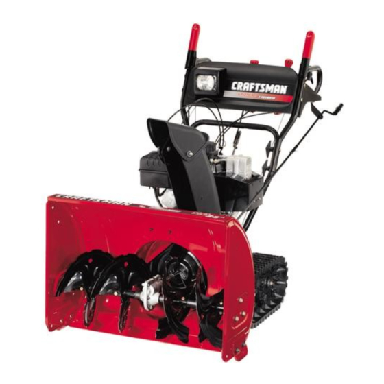
Owner's Manual
9 Horse Power
28" Two-Stage Track Drive
Snow Thrower
Model No.
247.88890
CAUTION:
Before
using this product,
read this manual and
follow all safety rules
and operating
instructions.
Safety
Assembly
Operation
Service
Maintenance
EspaRol
Sears, Roebuck And Co., Hoffman
Estates, IL 60179, U.S.A.
Visit our website: www.sears.com/craftsman
FORM NO. 770-10051 F
Printed in U.S.A.
(5/2004)
Advertisement
Table of Contents

Subscribe to Our Youtube Channel
Related Manuals for Craftsman 247.88890


Summary of Contents for Craftsman 247.88890
- Page 1 Assembly read this manual and Operation Service follow all safety rules Maintenance and operating instructions. EspaRol Sears, Roebuck And Co., Hoffman Estates, IL 60179, U.S.A. Visit our website: www.sears.com/craftsman FORM NO. 770-10051 F Printed in U.S.A. (5/2004)
- Page 2 Sears will repair, free of charge, any defect in material and workmanship. If this Craftsman snow thrower is used for commercial or rental purposes, this warranty applies for only 30 days from the date of purchase.
- Page 3 ARNING: the personal safety and/or property of yourself and others. Read and follow all instructions in this manual This symbol points out important safety instructions which, if not followed, could endanger before attempting to operate this machine. Failure to comply with these instructions may result in personal injury.
- Page 4 4. Never operate with a missing ordamaged chute Before cleaning, repairing, or inspecting machine assembly. Keep allsafety d evices inplace and working. disengage all control levers and stop the engine. Wait 5. Never runanengine i ndoors orinapoorly v entilated until the auger/impeller come to a complete stop. area.
- Page 5 Remove handle knob A, washer and eyebolt Unpacking attached to the left lower handle. Follow the Remove screws/staples from top sides and ends of direction of arrows in Figure 2. Do not remove the the shipping crate. Set panel aside to avoid tire eyebolt from the chute directional control.
- Page 6 9. Secure thechutedirectional control tothebracket Chute Clean-Out Tool withflatwasher a ndhairpin clip.SeeFigure 5. This tool, along with the electric cord, is fastened with a cable tie to the rear of the auger housing for shipping Spiral purposes. Cut cable tie and remove electric cord before operating the snow thrower.
- Page 7 5. Squeeze drive control a gainst t hehandle andpull However, if you have to operate the snow thrower on thestarter. T hetracks should turn. gravel, keep the skid shoe in the highest position for 6. Nowrelease thedrivecontrol a ndpullthestarter maximum clearance between ground and shave plate. again.
- Page 8 Read thisowner's manual a ndsafety rulesbefore operating y oursnow thrower. C ompare illustration b elowwith yoursnow thrower t ofamiliarize y ourself withthelocation ofvarious controls a ndadjustments. Operating Controls (See Figure 10 .) Drive Control/Auger Lock ¢ ..Shift Lever Chute Distance Control Headlight Auger Control Electric Starter Switch...
- Page 9 Chute Distance Control Packed Snow: Locks the front end of the snow thrower The chute distance control lever on down to the ground for hard-packed or icy snow conditions. the handle panel adjusts the angle of the chute. Move this lever forward to decrease the distance and rearward to increase the distance that snow is thrown.
- Page 10 CAUTION: Never u seengine orcarburetor cleaner Plug the other end of the power cord into a three- products i nthefueltank. hole, grounded 120 volt A.C. receptacle. 10. Push primer button three times, • Fillthefueltankoutdoors a ndusea funnel o r spout making sure to cover vent hole toprevent s pilling.
- Page 11 Allow the engine to warm up for a few minutes Wipe off all snow and moisture from the carburetor because the engine will not develop full power until area and around the engine. it reaches operating temperature. Operate the engine at full throttle (FAST) when ARNING: The temperature of muffler and surrounding areas may exceed 150 °...
- Page 12 • If, however, you have to operate the snow thrower on gravel, keep the skid shoe in the highest position ARNING: snow and ice from the discharge chute or Never use your hands to clean for maximum clearance between the ground and auger housing.
- Page 13 General Recommendations • Follow maintenance schedule below. • Periodically check all fasteners and make sure • Always observe safety rules when performing any these are tight. maintenance. • The warranty on this snow thrower does not cover items that have been subjected to operator abuse ARNING: inspecting, disengage all clutch levers and stop Before lubricating, repairing, or...
- Page 14 Lubrication Grease Fittings Engine Refer to the separate engine manual packed with your unit for all engine lubrication instructions. Gear Shaft Lubricate the gear shaft with 6-n-1 grease at least once a season or after every 25 hours of operation (available at automotive stores).
- Page 15 the snow thrower housing. See Figure 16. Reassemble the new shave plate with heads of WARNING: spark plug wire and move it away from the Always stop engine, disconnect carriage bolts to the inside of the housing. Tighten spark plug before performing any adjustments securely.
- Page 16 Auger Belts Drive Roll the front and rear auger belts off the engine Disc pulley. See Figure 19. Support Bracket oort Bracket Auger Dri,_e Belt Idler Pulley Figure 21 Replacing FrictionWheelRubber Figure 19 The rubber on the friction wheel is subject to wear and Unhook the idler spring from the hex bolt on the should be checked every 25 hours of operation;...
- Page 17 With the engine off, move the shift lever all the way Shift R od forward to the highest speed. With the drive control _procket Assembly Spacer lever released, push the snow thrower forward. The unit should roll forward. Then engage the drive control grip.
- Page 18 If the answer was negative in steps 9 and 10, further Remove the hairpin clip and slide the shift rod adjustment is necessary. connector up, to separate the upper shift rod from the lower shift rod. See Figure 27. 11. Loosen the jam nut on the drive control cable. Place the shift lever into the sixth (6) position.
- Page 19 If your snow thrower is left unused for 30 days or longer, storage for 30 days or longer. it needs to be prepared for storage. Also, at the end of NOTE: Also experience indicates that alcohol blended the snow season, you should follow the same set of fuels (called gasohol or using ethanol or methanol) can instructions and store the snow thrower properly for the attract moisture which leads to separation and...
- Page 20 Problem Cause Remedy Engine fails to start Fuel tank empty, or stale fuel. Fill tank with clean, fresh gasoline. Fuel becomes stale after thirty days. Blocked fuel line. Clean the fuel line. Choke not in the ON position Move switch to the ON position Faulty spark plug.
- Page 21 SAFETY & DECORATIVE L ABELS 777122363 777D08420 777120324 777122386 777122387 777122388 REF. 777S32236 777S32066 777D08419...
- Page 22 Craftsman Snowthrower Model 247.88890 i. _ Part of handle panel for reference only 66 t, .-20 3- ..T;9 , ..,_'/_ "i 5 ..10 80 / 79 /...
- Page 23 Craftsman Snowthrower Model 247.88890 Ref. Ref. Part No. Part Description Part Description Part No. 684-0008A Jam Lock Nut 3/8-24 Shift Arm Assembly 712-0116 705-5204A Chute Directional Control 712-04063 Flange Lock Nut 710-0449 Cotter Pin Carriage Screw 5/16-18 x 2.25 714-0104...
- Page 24 Craftsman Snowthrower Model 247.88890 .."...
- Page 25 Craftsman Snowthrower Model 247.88890 Ref. Ref. Part No. Part Description Part Description Part No. 712-0116 Lock Jam Nut 3/8-24 790-00087 Bearing Housing 756-0178 Flat Idler 710-0726 Hex Screw 5/16-12 784-5632B Auger Idler Arm 725-0157 Cable Tie (not shown) 710-0459A Hex Cap Screw 3/8-24 x 1.50...
- Page 26 Craftsman Snowthrower Model 247.88890 Suppli_ on engine 11 10 19 16 21 16 22 \...
- Page 27 Craftsman Snowthrower Model 247.88890 Ref. Part No. Part Description 710-1652 Hex Washer Screw 1/4-20 x.625 731-1324 Belt Cover 732-0710 Extension Spring 710-0627 Hex Screw 5/16-24 x.75 710-3005 Hex Cap Screw 3/8-16 x 1.25 05896A Drive Clutch Idler Bracket 748-0234 Shoulder Spacer...
- Page 28 Craftsman Snowthrower Model 247.88890 NOTE: For painted parts, please refer to the list of color codes below. Please add the applicable color code, wherever needed, to the part number to order a replacement part. For instance, if a part, numbered 700-xxxx, is painted red, the part number to order would be 700-xxxx-0721.
- Page 29 Craftsman Snowthrower Model 247.88890 Ref. Ref, Part No. Part Description Part No. Part Description 736-0270 Bell Washer.265 ID x.75 OD 784-5648 Frame Cover 736-0176 Flat Washer 1/4 ID x.93 OD 710-0896 AB Screw 1/4-14 x.625 741-1111 748-0190 Hex Flange Bearing...
- Page 30 Craftsman Snowthrower Model 247.88890 15.._"_" 22 _ \\17...
- Page 31 Craftsman Snowthrower Model 247.88890 Ref. Ref. Part No. Part Description Part Description Part No. 720-0223 Chain Grip 713-0233 710-0604A Tap Screw, 5/16-18 x.625 618-0169A Track/Steering Shaft Assembly 784-5642 Track Lockout Plate 683-0024 Track Hub Assembly 710-0157 Chain Hex Cap Screw, 5/16-24 x.75...
- Page 32 Tecumseh Engine HMSK90-156569G For Craftsman Snow Thrower Model 247.88890 "169 370C _420 370K _.,.
- Page 33 Tecumseh Engine HMSK90-156569G For Craftsman Snow Thrower Model 247.88890 PaN No. Part No. Key No. Description Key No. Description 35385 650880 Lock Washer Cylinder 27652 Dowel Pin 650881 Flywheel Nut 650820 100. 35135A Screw, 1/4-20 x 0.5" Solid State Ignition (Incl. 101) 30969 101.
- Page 34 Tecumseh Engine HMSK90-156569G For Craftsman Snow Thrower Model 247.88890 PaN No. Key No. Description Key No. Part No. Description 260. 35447A Blower Housing 329. 610973 Terminal 261. 650788 Screw, 5/16-18 x 3/4" 335. 36547 Carburetor Cover 262. 651084 Screw, 5/16-18 x 9/16"...
- Page 35 Tecumseh Engine HMSK90-156569G For Craftsman Snow Thrower Model 247.88890 Part No. Key No. Description 640052 Carburetor 631776A Throttle Shaft & Lever Assembly 631970 Throttle Return Spring 631778 Throttle Shutter 650506 Shutter Screw 632112 Choke Shaft & Lever Assembly 632174 Choke Shutter...
- Page 36 Tecumseh Engine HMSK90-156569G For Craftsman Snow Thrower Model 247.88890 Part No. Key No. Description 590749 Rewind Starter 590599A Spring Pin (Incl. 4) 590600 Washer 590679 Retainer \\\\\\ 590601 Washer 590678 Brake Spring 590680 Starter Dog 590412 Dog Spring 590682 Pulley & Rewind Spring Assembly...
- Page 37 Tecumseh Engine HMSK90-156569G For Craftsman Snow Thrower Model 247.88890 33329E Electric Starter 110 Volt (optional) 33451 Dust Cover 33842 Retainer Ring 33430 Spring Retainer 33431 Anti-Drift Spring 37050 Gear & Nut (Incl• 2) 35449 Drive End Cap Assembly 35450 "O" Ring...
- Page 38 EL SERVlCIO DE GARANT.IA ESTA DISP.ONIBLE PARA LOS USUARIOS QUE LLEVEN LA M,_QUINA QUITANIEVE CRAFTSMAN AL CENTRO DE PARTES & REPARACION SEARS MAS CERCANO DENTRO DE LOS ESTADOS UNIDOS.
- Page 39 peligro la seguridadpersonaly/o la propiedadsuyay de terceros.Lea y siga todas las instruccionesen este manualantes de ADVERTENCIA: Estesfmboloindicainstruccionesde seguridadimportantesque de no seguirse,se podrfaponer en iniciarla operaci6nde esta m_quina.En case de no seguir estasinstruccionespodrfaprovocar lesionespersonales.Cuando veaeste sfmbolo--preste atenci6n a la advertencia. veNculocontieneno emiten productosqufmicos que el estado de Californiaconsideraque pueden producirc_.ncer, d efectos ADVERTENClA: El escapedel motorde este producto,algunosde sus componentesy algunoscomponentesdel de nacimientou otros problemasreproductivos.
- Page 40 8. Sea sumamente precavido cuando opere l am_.quina sobre una Antes de realizar la limpieza, reparar o revisar la maquina, superficie con grava ocuando lacruce. Mantengase alerta per desengrane todas las palancas de control y detenga el motor. sisepresentan peligros ocultos otransito. Espere a que la barrena / motor se detenga per complete.
- Page 41 Desempaque Retire los tornillos / grapas de los lados y extremos superiores Control de la caja de embalaje. Retire el panel para evitar que se direccional pinchen las Ilantas o que se produzcan lesiones personales. Retire y descarte la bolsa de plastico que cubre la unidad. del canal Retire cualquier parte suelta que se incluya con la unidad (per Perno j...
- Page 42 Perilla demanija B Arandela curva _ Perno d eojo Perilla d emanija "..,.Varilla "de cambi inferior Figura 4 Inserte e pemo de carro a traves del orificio inferior de las Figura 6 manijas superior e inferior en el lado derecho, y asegt]relo con NOTA: Si el conector no esta montado correctamente, la segunda perilla de manija A y la arandela curva.
- Page 43 embrague debefia estar flojo. Ajuste la contratuerca para asegurar el cable una vez alcanzado el ajuste correcto. Empu_adura deemb[ague. NOTA: los cables estan mal ajustados si las barrenas Contra ..siguen girando cuando se suelta el embrague de las tuerca mismas, o si la maquina sigue en funcionamiento cuando se suelta el embrague de la transmisidn.
- Page 44 Lea este manual del propietario y las reglas de seguridad antes de poner en funcionamiento su maquina quitanieve. Compare las ilustraciones que aparecen debajo con su unidad para familiarizarse con la ubicaci6n de los distintos controles y ajustes. Controles de operacibn (Yea la Figura 10 ) >_Traba del control de transmisi6n / Barrena...
- Page 45 Control de distancia Nieve muy compactada: bloquea la parte frontal de la ma.quinaquitanieve pegada al suelo para condiciones de canal nieve muy compactada o congelada. La palanca de control de distancia del canal, situada en el panel de la manija, ajusta el a.ngulodel canal.
- Page 46 combustible si se dejan en el depdsito durante el encendido dentro de la ranura. No gire la Ilave. Guarde la almacenamiento. segunda Ilave en un lugar seguro. Rote la perilla de obturacion a posicidn FULL (maximo). PRECAUCl6N: Nunca use productos de limpieza para el Muevaelcontrol d elestrangulador a laposicidnFAST(rapido).
- Page 47 posici6n OFF. Si e lmotor falla, gire hacia p osicion FULL, luego estrangulador basra la posici6n OFF (apagado) y saque la mueva lentamente hacia posici6n OFF. Ilave. No gire la Ilave. 7. Deje q ue elmotor se enfrie por a lgunos minutes yaque el Limpie toda la nieve y la humedad del _.readel carburador y motor noalcanzar_, lapotencia...
- Page 48 PRECAUClON: No se recomienda operar esta parteposteriorde lacaja de la barren&Yea la Figura 12. Useelextremeconforma de palade laherramientapara destapary maquina quitanieve sobre grava. recoger lanievey el hieloacumuladosalrededordel canal de • Sin embargo, si por algQn motivo tiene que usar la descarga.
- Page 49 las temporadas. Recomendaciones generales Siga el cronograma de mantenimiento que se • Respete siempre las reglas de seguridad cuando presenta a continuaci6n. realice tareas de mantenimiento. Revise peri6dicamente todos los sujetadores y • La garantfa de esta maquina quitanieve no cubre compruebe que esten bien ajustados.
- Page 50 1. Con e lmotor ubicado ensuelo p arejo, elaceite debe e star enla lubricante. Vea la Figura 15. marca FULL ( lleno) delavarilla del n ivel deaceite. Vea la Es posible encontrar accesorios de engrasado en cada Figura 13. extremo del eje de la barrena. Lubrique con una pistola de 2.
- Page 51 tuercas hexagonales que ajustan dicha placa a la caja de la m_.quinaquitanieve. Yea la Figura 16. Vuelva a ensamblar la placa de raspado nueva con las cabezas desconecteel cablede la bujfay p6ngaloseparadode ADVERTENClA: Detengasiempreel motor, de los pernos de carro en el lade interior de la caja. Ajt]stela la mismaantes de realizartodo tipo de ajusteso bien.
- Page 52 Correas de las barrenas Saque las correas de las barrenas frontal y trasera de la polea del motor. Vea la Figura 19. Mensula de soporte Poleal de la I Cor_ea Ioca ..transmisi6n Correa cdrre_ Figura 21 de a barren_ Reemplazo de la gomadela ruedade Figura 19 fricci6n...
- Page 53 control de transmisi6n, empuje la maquina quitanieve hacia Rueda d entada Montaje delante. La unidad debe@ avanzar. Luego engrane la lavarilla de empuSadura del control de transmision. Las ruedas deberfan Separador Jcambio dejar de girar. Suelte la empu_adura de control de transmisi6n y empuje nuevamente la unidad.
- Page 54 10. Habiendo engranado elcontrol detransmisi6n, controle sila Retire el broche de horquilla y deslice el conector de la varilla rueda defricci6n hace c ontacto con laplaca d etransmisi6n. de cambio hacia arriba, para separar la varilla de cambio Vea laFigura 26. superior de la inferior.
- Page 55 Si su maquina quitanieve no se va a utilizar durante 30 ecendido. Para evitar estos problemas, el sistema del dias o mas, tiene que prepararla para el combustibledebe ser vaciadoantes de almacenar la almacenamiento. Asimismo, al final de la temporada de maquina durante 30 dias o mas.
- Page 56 Problema Causa Remedio El motor no arranca El dep6sito de combustible est_.vado o el Llene el tanque con gasolina limpia y fresca. El combustible es viejo. combustible envejece transcurridos treinta dias. La Ifnea del combustible esta bloqueada. Limpie lalfnea del combustible. La palanca de obturaci6n no esta en la posici6n Mueva el interrupter a la posici6n ON (encendido) ON (encendido).
- Page 57 YOUR NOTES...
- Page 58 YOUR NOTES...
- Page 59 YOUR NOTES...
- Page 60 Your Home For repair-in your home-of all major brand appliances, lawn and garden equipment, or heating and cooling systems, no matter who made it, no matter who sold it! ....iiiiiiiiiiiiiiiiii iiiiiiiiiiiiiiiiii For the replacement parts, accessories owner's manuals that you need to do-it-yourself....
Need help?
Do you have a question about the 247.88890 and is the answer not in the manual?
Questions and answers