Craftsman 247.888530 Owner's g Owner's Manual
9 horse power 28" two-stage wheel drive snow thrower
Hide thumbs
Also See for 247.888530 Owner's g:
- Owner's manual (64 pages) ,
- Owner's manual (64 pages) ,
- Owner's manual (64 pages)
Table of Contents
Advertisement
Quick Links
Owner's Manual
9 Horse Power
28" Two-Stage
Wheel Drive
Snow Thrower
Model No.
247.888530
CAUTION: Before
using this product,
read this manual and
follow all safety rules
and operating
instructions.
•
Safety
•
Assembly
•
Operation
•
Service
•
Maintenance
•
EspaSol
Sears, Roebuck
And Co., Hoffman
Estates,
IL 60179, U.S.A.
Visit our website: www.sears.com/craffsman
770-10057D
Printed in U.S.A.
(712000)
Advertisement
Table of Contents

Related Manuals for Craftsman 247.888530 Owner's g


Summary of Contents for Craftsman 247.888530 Owner's g
- Page 1 Owner's Manual 9 Horse Power 28" Two-Stage Wheel Drive Snow Thrower Model No. 247.888530 CAUTION: Before • Safety using this product, • Assembly read this manual and • Operation • Service follow all safety rules • Maintenance and operating instructions. •...
- Page 2 Sears will repair, free of charge, any defect in material and workmanship. If this Craftsman snow thrower is used for commercial or rental purposes, this warranty applies for only 30 days from the date of purchase.
- Page 3 This symbol points out important safety instructions which, if not followed,could endanger the personal safety and/or propertyof yourself and others. Read and follow all instructionsin this manual before attempting to operate your snow thrower. Failureto complywith these instructionsmay resultin personal injury.When you see this symbol--heed its warning. Your snow thrower was built to be operated according to the rules for safe operation in this manual.
- Page 4 Use only attachments and accessories (such as wheel weights, counter weights, cabs, etc.) approved Following are representations of some of the safety labels on your Craftsman snowthrower. Please follow the instruction on these labels and maintain safety while using or servicing the equipment.
- Page 5 Lay the hardware pieces from the hardware pack on the figure here and you will have automatically sorted these according to the steps of the assembly procedure described later. (Only one unit of each hardware has been shown per group. The number in parenthesis indicates the total number of the hardware needed in that group.) Lock Washer (4) Hex Bolt_(6)
- Page 6 Rear Right Chute Handle Panel • Handles Shift Crank __¢:_ Electric Start Cord Figure I c. Electric Start Cord IMPORTANT: This unit is shipped with engine oil in the engine, but without gasoline. After assembly, see d• Two-piece Chute Crank Assembly OPERATION section of this manual for fuel selection e•...
- Page 7 Secure bottom hole inthehandle tothesnow Attach the handle panel to the handle with two thrower using 5/16x .75" hexbolt a ndlock carriage bolts, cupped washers (cupped side washer from thehardware pack(group A on against the handle panel) and hex nuts on each page 5 ).Donot t ighten a tthis time.
- Page 8 Inserthex bolt through the upper chute crank • Place the other 3/8 ID flat washer (from the bracket, handle panel support, and upper left same group of hardware) on the end of the chute handle. Secure the bracket using cupped crank and insert hairpin clip into hole at the end washer and hex nut.
- Page 9 Tighten all loosehardware on the handle Attaching Shift Rod assembly in the following order -- first the four • Place the shift lever in the sixth (6) speed. hex bolts at the bottom of the handle, then the • Place the bentend ofthe shiftrod intothe hole in carriage bolts and lastly the hex bolts on the rear the shiftarm assembly.
- Page 10 Place the cable barrel fitting into the hole in the trigger. You can find the triggers and associated Trigger Cable hardware in group H of the hardware pack. See Figure 12. Trigger Assembly Inner Cable Cable_ !Hroi guger g Figure 14 Secure the left turn trigger cable to the lower Barrel handle using the other cable tie.
- Page 11 Skid Shoe Final Adjustments The space between the shave plate and the ground Auger Control can be adjusted. For close snow removal, place skid shoes in the low position. Use middle or high position • To check the adjustment of the auger control, when area to be cleared is uneven.
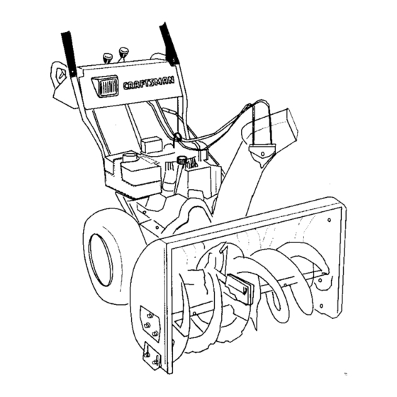
- Page 12 Knowing Your Snow Thrower Read this owner's manual and safety rules before operating your snow thrower. Compare illustration below with your snow thrower to familiarize yourself with the location of various controls and adjustments. Save this manual for future reference. The operation of any snow thrower can result in foreign objects being thrown into the eyes, which can result in severe eye damage.
- Page 13 Chute Distance Control Lever Operating Controls The distance that snow is thrown can be adjusted by (See Figure 17.) adjusting the angle of the chute assembly. Push the Chute Crank chute distance control lever forward to move the The chute crank is located on the left hand side of the upper chute down and decrease the distance.
- Page 14 Toavoid engine p roblems, thefuelsystem should be Determine whether your house wiring is a three- emptied before s torage f or30days orlonger. Drain the wire grounded system. Ask a licensed gas tank, s tart t heengine a ndletitrununtil t hefuel electrician if you are not certain.
- Page 15 • Make sure thattheauger d rive andthetraction As the engine warms up and begins to operate drive levers areinthedisengaged RELEASED evenly, rotate the choke knob slowly to OFF position. position. If the engine falters, return to FULL • Move throttle c ontrol lever t oFAST position. choke, then slowly move to OFF choke position.
- Page 16 Discharge snow downwind whenever possible. must be released. Slightly overlap each previous swath. WARNING: To stop the auger, both levers Set the skid shoes 1/4" below the scraper bar for normal usage. The skid shoes may be adjusted To Throw Snow upward for hard-packed snow.
- Page 17 General Recommendations All adjustments in the Service and Adjustments section of this manual should be checked at • Always observe safety rules when performing least once each season. any maintenance. Follow the maintenance schedule given below. • The warranty on this snow thrower does not Periodically check all fasteners and make sure cover items that have been subjected to these are tight.
- Page 18 Lubrication Check V-belts For a view of the lubricationpoints on the snow Follow the instructionsbelowto check the condition thrower, see Figure 19. of the drive belts every 50 hours of operation. Remove the plasticbelt cover on the front of the Sprocket Shaft engine by removing two self-tapping screws.
- Page 19 When engine is drained of all oil, replace drain plug securely. colder_ F_warmer Remove the dipstick from the oil fill. For location 5W30 _ _--_ SAE30 of the oil fill, see Figure 17. Pour fresh oil srowly through the plug. Replace dipstick. Check and make sure that the level of oil is up to Viscosity Chart the FULL mark on the dipstick.
- Page 20 and the drive plate in all positions of the shift WARNING: Always stop the engine, dis- lever. connect spark plug wire and move it away from the spark plug before performingany With the traction drive clutch engaged, the adjustments or repairs. friction wheel must contact the drive plate (shown in Figure 30).
- Page 21 Carburetor bolts, bellevillewashers and hex nuts which attach shave plate to the snow thrower housing. WARNING: If any adjustments are made For location of shave plate, see Figure 23. to the engine while the engine is running Reassemble new shave plate, making sure (e.g.
- Page 22 Remove t hesixhexnuts andlockwashers To remove the front auger drive belt, push the which attach theauger h ousing a ssembly tothe idler pulley to the left. See Figure 28. The belt frame assembly. SeeFigure 2 6. brake should move outward. Lift the front auger drive belt from the front auger pulley.
- Page 23 Reinstall thebeltcover o nfrontoftheengine Changing Friction Wheel Rubber withthetwoself-tapping screws a ndflat Check the rubber on the friction wheel after 25 washers. hours of operation, and periodically thereafter. Reattach thechute crank tothechute assembly Replace the rubber if any signs of wear or withthehairpin clipandflatwasher.
- Page 24 Shift Arm Assembly Sprocket Sha_- Figure 33 Align the hex shaft with the right hand bearing and carefully guide the left hand bearing into the left side of the housing. Reassemble the drive cover with the four screws that were earlier removed. Note: If you placed plastic under the gas cap, be certain to remove it.
- Page 25 If the snow thrower will not be used for 30 days or WARNING: Drain fuel into approved longer, or at the end of the snow season when the last container outdoors,away from any open possibility of snow is gone, the equipment needs to flame.
- Page 26 Trouble Possible Cause(s) Corrective Action Enginefailsto start Fueltankempty, o r stalefuel, Fill tank with clean, fresh gasoline. Fuel will not last over thirty _ays unless a fuel stabilizer is used. Blocked fuel line. Clean fuel line. Choke not in ON position Move switch to ON position Faulty spark plug.
- Page 27 777120729 777120728 777120727 777D00334 777120329 (CENTER MODEL PLATE WITH TOP OF FRAME COVER) 777830511 77788O514...
- Page 28 SEARS CRAFTSMAN 9.0 H.P. SNOW THROWER MODEL 247.888530 NOTE: For painted parts, please refer to the list of color codes below. Please add the applicable color code, wherever needed, to the part number to order a replacement part. For instance, if a part, numbered 700-xxxx, is painted polo green, the part number to order would be 700-xxxx-0689.
- Page 29 SEARS CRAFTSMAN 9.0 H.P, SNOW THROWER MODEL 247.888530 Key No. Pad No. Description Key. No. Part No. Description 05931A Bearing Housing 736-0167 Flat Washer 684-0041C Auger Housing Assy. 28" 736-0188 Flat Washer 684-0065 Impeller Assy. 12" dia. 736-0242 Belleville Washer...
- Page 30 SEARS CRAFTSMAN 9.0 H.P. SNOW THROWER MODEL 247.888530 NOTE: For painted parts, please refer to the listof co_or codes below. Please add the applicable color code, wherever needed, to the part number to order a replacement part. For instance, if a part, numbered 700-xxxx, is painted polo green, the part number to order would be 700-xxxx-0689.
- Page 31 SEARS CRAFTSMAN 9.0 H.P. SNOW THROWER MODEL 247.888530 Description Key, No Part No. Description Key. No. Part No. 618-6043 Bell Washer Dogg Assembly: RH 736-0105 Flat Washer 618-0044 Dogg Assembly: LH 736-0160 618-0303B Lock Washer Shift Assembly: Steerable Drive 736-0169...
- Page 32 SEARS CRAFTSMAN 9.0 H.P. SNOW THROWER MODEL 247.888530 NOTE: For painted parts, please refer to the list of color codes below. Please add the applicable color code, wherever needed, to the part number to order a replacement part. For instance, if a part, numbered 700- xxxx, is painted polo green, the part number to order would be 700-xxxx-0689.
- Page 33 SEARS CRAFTSMAN 9.0 H.P, SNOW THROWER MODEL 247.888530 Part No, Description Part No. Description Grease Harness for Headlight 737-0133 629-0058 Chute Deflector Control Cable Shift Arm Assembly 746-0896 684-0008A- 746-0901 0637 Chute Deflector Cable w/Clip Lower Chute Crank Assembly 684-0053A...
- Page 34 SEARS CRAFTSMAN 9.0 H.P, SNOW THROWER MODEL 247.888530 \\\\ Key, No Part No. Description 712-0324 Hex Lock Nut: 1/4-20 732-0705 Cable Guide Craftsman Engine model 143.999005 Key. No. Part No, Description 734-1709 Wheel Assembly: 16.5 x 4.8 Steerable 738-0994 Axle: 0.75" dia. x 12.201" Lg.
- Page 35 SEARS CRAFTSMAN 9.0 H.P. SNOW THROWER MODEL 247.888530 IMPORTANT: For a properly workingmachine, use FactoryApproved Parts. V-Belts are specially designed to engage and disengage safely. A substitute (non-OEM) V-Belt can be dangerous by not disengaging completely. NOTE: For painted parts, please refer to the list of colorcodes below.
- Page 36 Craftsman Engine Model No. 143.999005 for Craftsman Snow Thrower Model 247.888530 18 35 _120 ;351 "277 "\ 370C 370B 285 9Z...
- Page 37 Craftsman Engine Model No. 143.999005 for Craftsman Snow Thrower Model 247.888530 Part Part Qty. Qty. Description Description 35385 650881 Cylinder Flywheel Nut 27652 Dowel Pin 35135 Solid State Ignition 650820 610118 Screw Spark Plug Cover 651024 Oil Drain Extension Solid State Mounting Stud...
- Page 38 Craftsman Engine Model No. 143.999005 for Craftsman Snow Thrower Model 247.888530 Table continued from previous page Description aty. Description Qty. 35447A 35392 Starter Plug Blower Housing 650788 Screw 35593 Ignition Key 29747B 610973 i Terminal Screw, Torx 264A 650802 Screw...
- Page 39 Craftsman Engine Model No. 143.999005 for Craftsman Snow Thrower Model 247.888530 CARBURETOR Descdption Qty. 640052 Carburetor (Incl. 184 of Engine Parts List) 631776A Throttle Shaft & Lever Ass'y. 631970 Throttle Return Spring 631778 Throttle Shutter 650506 Shutter Screw 632112 Choke Shaft & Lever Ass'y.
- Page 40 In U.S.A. or Canada for in-home major brand repair service: Call 24 hours a day, 7 days a week (1-800-469-4663) 1-800-4-MY-HOME Para pedir servicio de reparaci6n a domicillio -- 1-800-676-5811 Au Canada pour tout le service ou les pieces -- 1-800-469-4663 For the repair or replacement parts you need: Call 6 a.m.
Need help?
Do you have a question about the 247.888530 Owner's g and is the answer not in the manual?
Questions and answers