Table of Contents
Advertisement
Quick Links
9040 Low Voltage Control Unit KIT For The
ESTA-QUICK and Evolver SE Applicators
MODELS:
80072-XXX for use with Esta-Quick Applicator AEMD500 (Atex approved)
80078-XXX for use with Evolver SE (Not Approved)
IMPORTANT: Before using this equipment, care-
fully read SAFETY PRECAUTIONS, starting on
page 1, and all instructions in this manual. Keep
this Service Manual for future reference.
SERVICE MANUAL
CP-11- 01.02
Advertisement
Table of Contents
Troubleshooting

Summary of Contents for Ransburg 9040
- Page 1 SERVICE MANUAL CP-11- 01.02 9040 Low Voltage Control Unit KIT For The ESTA-QUICK and Evolver SE Applicators MODELS: 80072-XXX for use with Esta-Quick Applicator AEMD500 (Atex approved) 80078-XXX for use with Evolver SE (Not Approved) IMPORTANT: Before using this equipment, care- fully read SAFETY PRECAUTIONS, starting on page 1, and all instructions in this manual.
- Page 2 CP-11-01...
-
Page 3: Table Of Contents
9040 Low Voltage Control Unit Kit- Contents CONTENTS PAGE SAFETY: ......................SAFETY PRECAUTIONS HAZARDS/SAFEGUARDS ......................ATEX EUROPEAN ATEX DIRECTIVE ....................EUROPEAN ATEX LABELS ....................... INTRODUCTION: 7-10 DESCRIPTION ................................................... SPECIFICATIONS 9040 CASCADE CONTROL UNIT FEATURES ................. INSTALLATION: 11-20 LOCATION ........................... -
Page 4: Safety
9040 Low Voltage Control Unit Kit- Safety SAFETY SAFETY PRECAUTIONS W A R N I N G > The user MUST read and be familiar with Before operating, maintaining or servicing any Ransburg electrostatic coating system, read the Safety Section in this manual and the... -
Page 5: Hazards/Safeguards
9040 Low Voltage Control Unit Kit- Safety AREA HAZARD SAFEGUARDS Tells where hazards Tells what the hazard is. Tells how to avoid the hazard. may occur. Spray Area Fire Hazard Fire extinguishing equipment must be present in the spray area and tested periodically. - Page 6 9040 Low Voltage Control Unit Kit- Safety AREA HAZARD SAFEGUARDS Tells where hazards Tells what the hazard is. Tells how to avoid the hazard. may occur. General Use and Improper operation or maintenance Personnel must be given training in accordance with Maintenance may create a hazard.
- Page 7 9040 Low Voltage Control Unit Kit- Safety AREA HAZARD SAFEGUARDS Tells where hazards Tells what the hazard is. Tells how to avoid the hazard. may occur. Spray Area / This is a high voltage device that Parts being sprayed must be supported on conveyors...
-
Page 8: Atex
9040 Low Voltage Control Unit Kit- Atex EUROPEAN ATEX DIRECTIVE 94/9/EC, ANNEX II, 1.0.6 8. The certification of this equipment relies upon The following instructions apply to equipment the following materials used in its construction: covered certificate number Sira 11ATEX5240X: If the equipment is likely to come into contact with 1. -
Page 9: European Atex Labels
9040 Low Voltage Control Unit Kit- Atex Label 72562 9040 Cascade Low Voltage Control Unit Kit ATEX Product Marking Definitions Ex Certificate Number: Sira 11ATEX5240X Sira = Notified Body performing EC-type examination 11 = Year of certification ATEX = Reference to ATEX Directive... -
Page 10: Introduction
A combination triple setpoint/analog input control A regulated pressure fluid system delivers coating board is also supplied with 9040 Cascade control material to the atomizer. At the atomizer, air is units powering automatic spray applicators. - Page 11 9040 Low Voltage Control Unit Kit- Introduction The 9040 Cascade control unit has also been signal is removed from this input, the contacts of modularly designed so that two half rack 9040 the pressure switch are open and AC power to the chassis will fit into one full rack enclosure, in control unit is disconnected.
-
Page 12: Specifications
9040 Low Voltage Control Unit Kit- Introduction SPECIFICATIONS Environmental / Physical-Control Unit Height: 132 mm Width: 429 mm (483 mm ear to ear) Depth: 308 mm Weight: 6.8 kg Environmental / Cascade Height: 400 mm Width: 102 mm Square Weight: 4.1 kg... -
Page 13: 9040 Cascade Control Unit Features
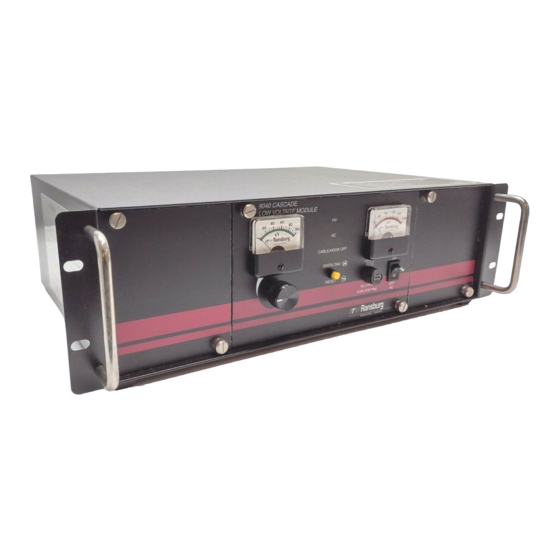
9040 Low Voltage Control Unit Kit- Introduction Front View Rear View Figure 1: 9040 Cascade Control Unit Features Number Description Kilovolt Meter AC Power ON Indicator High Voltage On Indicator Micro Amp Meter High Voltage Adjust Knob Cable Fault/Hook Off Indicator... -
Page 14: Installation
AC line cord into the receptacle in the rear of the 9040 Cascade control unit. Plug the other end of the line cord into a properly NOTE grounded 120-volt AC outlet. As each installation is unique, this >... - Page 15 9040 Low Voltage Control Unit Kit- Installation For installations where it is required to run the AC input wiring in conduit, perform the following: 1. Ensure the AC line cord is unplugged and remove the AC Inlet Receptacle wiring from 1TB-L1, 1TB-N and 1TB-Ground (see Figure 2 for AC input wiring locations).
-
Page 16: External Connections
If it becomes 9040 control unit chassis can still be slid necessary to slide the chassis out for out of its enclosure if required. For... - Page 17 A set of external relay contacts for high voltage the exhaust fan and conveyor. To interlock the (K1) and overload (K2) conditions is provided at 9040 Cascade control unit with the exhaust fan External Wiring Plug 2PL-5, -6 & -7 (outside) and conveyor perform the following: and 2SOC-5, -6 &...
- Page 18 External High Voltage Control External Overload Reset If a method of high voltage triggering, other than The 9040 Cascade control unit allows for use of an the factory supplied method, is required, the 9040 external (normally closed) overload reset button.
- Page 19 9040 Low Voltage Control Unit Kit- Installation Analog Current Output Signal An analog current output signal is available from the 9040 control unit at 2PL-8 (outside) or 2SOC-8 (inside). This signal can be connected to a recording device (strip chart recorder, data acquisition unit, etc.) to monitor the output...
- Page 20 9040 Low Voltage Control Unit Kit- Installation To utilize the Triple Setpoint Feature perform High voltage outputs selected by TB1-1 (Setpoint the following (refer to Figures 5a and 5b): 1) and TB1-3 (Setpoint 2) can be adjusted by tweaking potentiometers P1 and P2 on the Triple 1.
- Page 21 9040 Low Voltage Control Unit Kit- Installation C A U T I O N C A U T I O N > DO NOT operate the Analog Input > DO NOT use the analog input board Feature with the jumpers removed...
-
Page 22: Combination Triple Setpoint / Analog Input Board Layout
9040 Low Voltage Control Unit Kit- Installation Figure 5b: Combination Triple Setpoint/Analog Input Board Layout CP-11-01... -
Page 23: Typical Esta-Quick/Evolver Se Applicator Installation
9040 Low Voltage Control Unit Kit- Installation (Atex Approved) Hazardous Area Non-Hazardous Area 80072-XXX Figure 6A: Typical Installation Number Description 9040 Low Voltage Unit AGMD-500 Unit (Atex Approved) A10560-XXD High Voltage Cable 76300-03 External Cascade 76298-XX Low Voltage Cable Booth Wall... - Page 24 9040 Low Voltage Control Unit Kit- Installation (Not Atex Approved) Hazardous Area Non-Hazardous Area 80078-XXX Figure 6B: Typical Installation Number Description 9040 Low Voltage Unit Evolver SE A12455-XXXX (Non-Atex Approved) A10560-XXD High Voltage Cable 76300-01 External Cascade (Oil Filled) 76298-XX Low Voltage Cable...
- Page 25 9040 Low Voltage Control Unit Kit- Installation Cascade Ground Connection Cascade End Applicator End Figure 7: High Voltage Cable A10560-XXD Connection-Cascade End Connection-Control Unit End Figure 8: Low Voltage Cable 76298-XX CP-11-01...
-
Page 26: Operation
9040 Low Voltage Control Unit Kit- Operation OPERATION W A R N I N G W A R N I N G > The user MUST read and be familiar > The electrical discharge that is available with the SAFETY PRECAUTIONS and... -
Page 27: Operating Procedures
9040 Low Voltage Control Unit Kit- Operation High Voltage Adjustment Knob OPERATING The high voltage adjustment knob allows infinite PROCEDURES control of the applicator electrode voltage between 0 and rated kV. 1. Ensure that the AC power, low voltage Overload Indicator/Reset Button... - Page 28 High Voltage Safety Circuit OFF position. The 9040 Main PC board contains a safety circuit that prevents high voltage from being present at the applicator if the high voltage trigger device (pressure switch, PC contact, etc.) has not been...
- Page 29 9040 Low Voltage Control Unit Kit- Operation NOTES CP-11-01...
-
Page 30: Maintenance
9040 Low Voltage Control Unit Kit- Maintenance MAINTENANCE 3. Disconnect the low voltage cable and ROUTINE PREVENTIVE connect one lead of the ohmmeter to the MAINTENANCE ground stud and the other to the center pin of the low voltage cable socket on the control unit. - Page 31 To assist in testing and troubleshooting, a jumper When a lack of high voltage at the applicator indicates a problem, perform a Control Unit (JP4) has been incorporated on the 9040 PC Output Test on the control unit to determine board. By covering (shorting) both terminals the whether it is at fault.
- Page 32 9040 Low Voltage Control Unit Kit- Maintenance The DC input to the oscillator is interlocked with Equipment Required: Volt/ 2PL terminals 1 and 2, such that the oscillator Ohmmeter will not function unless terminals 1 and 2 of 2PL This...
- Page 33 9040 Low Voltage Control Unit Kit- Maintenance NOTES CP-11-01...
-
Page 34: Troubleshooting Flow Charts
9040 Low Voltage Control Unit Kit- Maintenance TROUBLESHOOTING FLOW CHARTS ON / OFF Switch ON ON / OFF Indicator (green LED) does not light CP-11-01... -
Page 35: Troubleshooting Diagram
9040 Low Voltage Control Unit Kit- Maintenance TROUBLESHOOTING FLOW CHARTS (Cont.) Figure 10: Troubleshooting Diagram CP-11-01... -
Page 36: 9040 Cascade Control Unit Block Diagram
9040 Low Voltage Control Unit Kit- Maintenance Figure 11: 9040 Cascade Control Unit Block Diagram CP-11-01... -
Page 37: Service Level
9040 Low Voltage Control Unit Kit- Maintenance 3. Remove fuse from fuse holder and replace W A R N I N G with new fuse (see “Parts Identification” section of this manual for fuse part number). > Always turn power to the control unit OFF, unplug the electrical cord from its 4. - Page 38 9040 Low Voltage Control Unit Kit- Maintenance NOTE W A R N I N G It is recommended that the four (4) ON/ > Always double-check that the control > unit is unplugged from its AC outlet before OFF switch wires be tagged with their...
- Page 39 9040 Low Voltage Control Unit Kit- Maintenance LED Display Board Pressure Switch (76580-4XXXX, - 1. Ensure control unit is unplugged from AC outlet, loosen front panel screws, and slide 5XXXX, -8XXXX, and -9XXXX) control unit chassis out. 1. Disconnect pressure signal input line from pressure switch.
- Page 40 9040 Low Voltage Control Unit Kit- Maintenance HV Adjust Potentiometer PC Board 1. Remove knob from HV adjust potentiometer 1. Ensure control unit is unplugged from AC by using a 1/16” Allen wrench to remove the two outlet, loosen front panel screws, and slide (2) set screws.
- Page 41 9040 Low Voltage Control Unit Kit- Maintenance NOTES CP-11-01...
-
Page 42: Parts Identification
9040 Low Voltage Control Unit Kit- Parts Identification PARTS IDENTIFICATION Figure 12a: 9040 Low Voltage Control Unit Kit Parts Diagram For Both 80072 and 80078 Units CP-11-01... - Page 43 9040 Low Voltage Control Unit Kit- Parts Identification Figure 12b: 9040 Low Voltage Control Unit Kit Parts Diagram For Both 80072 and 80078 9040 Low Voltage Control Unit Kit- PARTS LIST Item # Part # Description Notation 76892-41 PC Board and Heat Sink Assembly: For approved AEMD500...
-
Page 44: Recommended Spare Parts / Optional Equipment
CP-11-01... - Page 45 These modules may be ordered and installed as optional equipment with the 9040 unit. Installing this option allows control of parameters associated with the application process. The kits listed below may be directly integrated into the 9040 chassis to provide all controls for your system in one central location.
-
Page 46: Warranty Policies
9040 Low Voltage Control Unit Kit- Warranty Policies WARRANTY POLICIES LIMITED WARRANTY RANSBURG'S ONLY OBLIGATION UNDER THIS WARRANTY IS TO REPLACE PARTS THAT HAVE FAILED BECAUSE OF FAULTY Ransburg will replace or repair without charge WORKMANSHIP OR MATE-RIALS. THERE any part and/or equipment that falls within the... - Page 47 MANUAL CHANGE SUMMARY This manual was published new with the product release. 11/11 Added 76892-42 pc board for the Evolver SE or un-approved units. 02/12 Removed all reference to AEMD-503, Updated 72562 label.
- Page 48 Telephone: 800/ 233-3366 Fax: 419/ 470-2040 Toledo, Ohio 43612-1493 Telephone: 419/470-2021 www. itwransburg.com Technical Support Representative will direct you to the appropriate telephone number for ordering Spare Parts. Form No. CP-11-01 © 2011 Ransburg. All rights reserved. Litho in U.S.A.
- Page 49 Models and specifications subject to change without notice. 07/11...
Need help?
Do you have a question about the 9040 and is the answer not in the manual?
Questions and answers