
Related Manuals for Dover PSG NEPTUNE 610


Summary of Contents for Dover PSG NEPTUNE 610
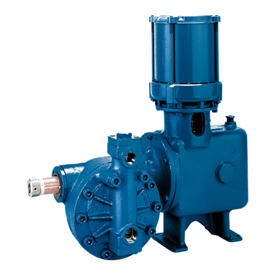
- Page 1 INSTALLATION OPERATION & MAINTENANCE NEPTUNE Series 600 “dia-PUMPS” Models 610 THRU 647 NEP-ZL105648 06.2019_REV 7...
-
Page 2: Safety Instructions
WARNING LOCKOUTS ARE REQUIRED BEFORE SERVICING THIS EQUIPMENT. SAFETY INSTRUCTIONS: Shut off/Lockout pump Power before Servicing. Be certain pump isolation valves are Closed and chemical is shut off. Bleed pressure before servicing. - Page 3 WARNING Please read thoroughly before installation, operation or maintenance of any Neptune pump EQUIPMENT MISUSE HAZARD Equipment misuse can cause the equipment to rupture, malfunction and result in serious injury. This equipment is for professional use only. • Read all instruction manuals, tags, and labels before operating the equipment. •...
- Page 4 FIRE AND EXPLOSION HAZARD Improper grounding, poor air ventilation, open flames, or sparks can cause a hazardous condition and result in fire or explosion and serious injury. Ground the equipment. See motor installation instruction for grounding procedure. • Do not pump non recommended flammable or explosive fluids. •...
-
Page 5: Table Of Contents
TABLE OF CONTENTS SECTION PARAGRAPH PAGE GENERAL DESCRIPTION — LIMITED WARRANTY PARTS ORDERING INSTRUCTIONS INSTALLATION INSTRUCTIONS — GENERAL SUCTION PIPING DISCHARGE PIPING ADJUSTMENT OF INTERNAL RELIEF VALVE INSTALLATION OUTDOORS START UP PROCEDURE NORMAL MAINTENANCE — 9-13 MAINTENANCE 9-13 MOTOR OPERATING CONDITIONS —... -
Page 6: I - General Description
SECTION I GENERAL DESCRIPTION The Neptune Series 600 “dia-PUMP” is a reliable metering pump of the high-pressure diaphragm type. Under constant conditions of temperature, pressure, and capacity adjustment settings, a plus or minus range of 1% metered discharge volume is maintained. ®... -
Page 7: Limited Warranty
LIMITED WARRANTY All Neptune Pumps are tested at the factory prior to shipment. Each part used in their construction has been carefully checked for workmanship. If the pump is installed properly, Neptune Chemical Pump Company warrants to the purchaser of this product for a period of thirty six months from the date of first use or eighteen months from shipment, whichever occurs first, this product shall be free of defects in material and/or workmanship, as follows: 1. -
Page 8: Parts Ordering Instructions
PARTS ORDERING INSTRUCTIONS The complete model number and serial number of the pump must be furnished to insure prompt and accurate parts service. These numbers are found on the name plate (sample below) located on the side of the pump. Refer to Section VII for complete parts lists. Send all orders or inquiries for parts to: Parts Department Neptune Chemical Pump Company... -
Page 9: Installation Instructions
SECTION II INSTALLATION INSTRUCTIONS 1.0 GENERAL 1.0.1 UNPACKING & INSPECTION When unpacking a pump or chemical feed system, be certain that no parts are thrown away. Examine the equipment for possible damage. If damage has occurred, file claim with the common carrier within 24 hours. -
Page 10: Suction Piping
Please note Figure 1, indicating the correct rotation. Operation with the incorrect rotation will damage the pump and motor. FIGURE I 1.0.8 Please note, that some items in the parts list have more than one part number for an individual figure number. -
Page 11: Discharge Piping
3.0 DISCHARGE PIPING 3.0.1 It is recommended that the "dia-Pump" operate against a minimum discharge pressure of 50 psig. 3.0.2 All Neptune Series 600 "dia-Pumps" are supplied with an internally pre-set relief valve. This relief valve approximately above actual rated discharge pressure pump... - Page 12 4.0.2 To reset the relief valve to a higher pressure (the relief valve setting cannot be reduced because of design considerations), instructions are as follows: Connect a test set-up as shown in Figure IV below. NOTE: All parts must have a 4.0.21 working pressure rating above the required set pressure.
-
Page 13: Installation Outdoors
INSTALLATION OUTDOORS The "dia-Pump" is a totally enclosed pump which can be used outdoors or indoors. When installed out- doors, make sure that the pump is protected against extremes of nature as follows: 5.0.1 Running of the pump when exposed to tropical sunshine with ambient temperature above 90°F (32°C) would cause excessive oil and motor temperatures. -
Page 14: Normal Maintenance
SECTION III PUMP MODELS 610 AND 615 NORMAL MAINTENANCE 7.0 MAINTENANCE Under normal conditions, the "dia-Pump" should not require any significant amount of maintenance. It is advised that periodic visual observations be made of the oil level; make sure that it is no more than 2" from the top of oil fill hole. -
Page 15: Maintenance
SECTION III PUMP MODELS 620 AND 625 NORMAL MAINTENANCE MAINTENANCE Under normal conditions, the "dia-Pump" should not require any significant amount of maintenance. It is advised that periodic visual observations be made of the oil level; make sure that it is no more than 2" from the top of oil fill hole. - Page 16 SECTION III PUMP MODELS 635, 637 NORMAL MAINTENANCE TO VIEW FIGURE NUMBERS: For Models 635 & 637 refer to Drawing on page 22. MAINTENANCE Under normal conditions, the "dia-Pump" should not require any significant amount of maintenance. It is advised that periodic visual observations be made of the oil level; make sure that it is no more than 2" from the top of oil fill hole.
- Page 17 SECTION III PUMP MODEL 647 NORMAL MAINTENANCE TO VIEW FIGURE NUMBERS: For Model 647 refer to Drawing on page 24. 7.2.2 MAINTENANCE Under normal conditions, the "dia-Pump" should not require any significant amount of maintenance. It is advised that periodic visual observations be made of the oil level; make sure that it is no more than 2" from the top of oil fill hole.
- Page 18 7.3.1 Procedure for replacing CONTROL ROD "O" RING (FIG. #1434 for Models 610 & 615, FIG. #2334 for Models 620 & 625, FIG. #3234 for Models 635, 637 & 647) and SEALING PLATE "O" Ring (FIG. #2333 for Models 620 & 625, FIG. #3233 for Models 635, 637 & 647). 7.3.11 Remove hydraulic fluid from gear box.
-
Page 19: Motor Operating Conditions
SECTION IV MOTOR OPERATING CONDITIONS The normal temperature rise for standard motors is 40°C above ambient temperature and, thus, it might appear that the motor is operating at a higher than normal temperature. This situation is normal and should not cause concern. As a precaution against motor overheating, it is recommended that the pump be located where adequate ventilation is available. -
Page 20: Troubleshooting Chart
SECTION V TROUBLESHOOTING CHART SYMPTOM CAUSE REMEDY 1. Pump Motor Will Not A. Blown Fuse. Check for short circuit or Operate. overload. B. Open thermal overload device Reset. in starter. C. Low liquid level in tank (where Fill tank. low level cut-off is used). D. - Page 21 SYMPTOM CAUSE REMEDY 3. Pump delivers erratically. A. Leaky suction line. Repair or replace piping. B. Worn or dirty valves or seats, Clean or replace valve or both. assembly. C. Excessive excursion of ball Increase back pressure. Valves from seats (indicated by ball chatter).
-
Page 22: Parts List And Pump Drawings
SECTION VI PARTS LIST FOR PUMP MODELS 610 & 615 (REFER TO DRAWING NO. 6100, PAGE 18) FIG. PART FIG. PART DESCRIPTION QTY. DESCRIPTION QTY. 0101 Gearbox 000349 0138 3/8” Lock Washer 100217 0102 Worm Gear 58 SPM 000350 0139 Screw 3/8-16 x 1”... - Page 24 SECTION VI PARTS LIST FOR PUMP MODELS 620 & 625 (REFER TO DRAWING NO. 6200, PAGE 20) FIG. PART FIG. PART DESCRIPTION QTY. DESCRIPTION QTY. 0101 Gearbox 000349 0140 Indicator Scale 100307 0102 Worm Gear 58 SPM 000350 0141 Screw 5/16-18 x 1-1/4” LG 100205 Worm Gear 117 SPM 000351...
- Page 26 SECTION VI PARTS LIST FOR PUMP MODELS 630, 635 & 637 (REFER TO DRAWING NO. 6300, PAGE 22) NOTE: N-3 PUMPS HAVE 316SS PUMP HEAD AND 316SS TRIM. N-4 PUMPS HAVE C-20 PUMP HEAD AND C-20 TRIM. FIG. PART FIG. PART DESCRIPTION QTY.
- Page 28 SECTION VI PARTS LIST FOR PUMP MODELS 647 (REFER TO DRAWING NO. 6347, PAGE 24) NOTE: N-3 PUMPS HAVE 316SS PUMP HEAD AND 316SS TRIM. N-4 PUMPS HAVE C-20 PUMP HEAD AND C-20 TRIM. FIG. PART FIG. PART DESCRIPTION QTY. DESCRIPTION QTY.
- Page 30 ADDENDUM 600 SERIES PVC PUMP THEORY OF OPERATION The NEPTUNE 600 PVC "dia-Pump" is a double diaphragm pump employing the basic drive unit of the Neptune series 600 "dia-Pump". All drive, stroke control parts and oil head are common to the original flat diaphragm models. An Intermediate plate and all parts in the liquid side are different from the basic pump.
- Page 31 ADDENDUM 635-647 SERIES “dia-PUMP" PUMPS WITH N5 (PVC) AND N8 (KYNAR) HEAD OPTIONS ITEM DESCRIPTION QTY. PART NO. PART NO. PUMP HEAD 004169 004170 CHECK VALVE ASS'Y. 004175 004176 5/8-11 X 4" LG. SCREWS 107603 107603 FLA T WASHERS 107857 107857 Recommended Spare Parts It is recommended that the following parts be kept in stock for a pump:...
-
Page 32: Spare Parts
SECTION VI 10.0 SPARE PARTS 10.0.1 Important-When ordering spare parts, please show MODEL NUMBER AND SERIAL NUMBER of pump for which parts are being ordered. This information can be found on a stainless steel nameplate riveted to the side of the pump. 10.0.2 Recommended Spare Parts for PUMP MODELS 610 AND 615 (THIS PUMP IS NO LONGER OFFERED) It is recommended that the following parts be kept in stock for a pump:... -
Page 33: Appendix
APPENDIX DOUBLE DIAPHRAGM OPTION ADDENDUM: Special instructions for Series 630 & 640 “dia-Pumps” with Double Diaphragm THEORY OF OPERATION The instructions below are for Neptune’s optional Double Diaphragm Kit which is available for the Neptune Series 630 and 640 “dia-Pumps”. Use of a double diaphragm allows diaphragm to be monitored and provides an early warning upon failure of either diaphragm allowing repairs to be made before... - Page 34 APPENDIX DOUBLE DIAPHRAGM OPTION ADDENDUM: Special instructions for Series 630 & 640 “dia-Pumps” with Double Diaphragm 1.0.8 Close valve Item No. 5 1.0.9 Remove the vacuum pump. Plug valve Item No. 5 with a 316SS pipe plug Item No. 12 1.0.10 Reinstall the Pump 1.0.11...
- Page 35 EC Declarations for Diaphragm Metering Pumps Manufacturer: PSG California 22069 Van Buren Street Grand Terrace, CA 92313 USA Director of Engineering: Chris Distaso Signature: Representative authorized to compile technical files in the European Community: ALMATEC Maschinenbau GmbH Carl-Friedrich-Gauß-Straße 5 D – 47475 Kamp-Lintfort Germany General Manager: Rainer Wulf Signature:...
- Page 36 MAINTENANCE LOG Serial #_______________________________ Pump Model___________________________ Maximum Flow________________________ Strokes Per Minute______________________ Maximum Pressure_____________________ Piston Diameter________________________ Spare Parts Kit #____________________________________________________________ NEPTUNE CHEMICAL PUMP CO. Tel.: 215-699-8700 • FAX: 215-699-0370 DATE SERVICED BY MAINTENANCE PERFORMED...
- Page 37 Revision 1 Revision 2, 9-13-2010 Revision 3, 1-18-2011 Revision 4, 7-17-2012 Revision 5, ECN-3255, 5/19/2015 Revision 6, 03/15/2018 © Copyright 2012 Neptune Chemical Pump Company, Printed in U.S.A NEP-ZL105648...
Need help?
Do you have a question about the PSG NEPTUNE 610 and is the answer not in the manual?
Questions and answers