
Related Manuals for Dover PSG Neptune 600 Series


Summary of Contents for Dover PSG Neptune 600 Series
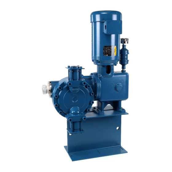
- Page 1 INSTALLATION OPERATION & MAINTENANCE NEPTUNE 600 Series Hydraulic Metering Pumps NEP-ZL105648 06.2024_REV 7...
- Page 2 WARNING LOCKOUTS ARE REQUIRED BEFORE SERVICING THIS EQUIPMENT. SAFETY INSTRUCTIONS: Shut off/Lockout pump Power before Servicing. Be certain pump isolation valves are Closed and chemical is shut off. Bleed pressure before servicing. In case of emergency, shut pump down completely by disconnecting motor power supply.
- Page 3 WARNING Please read thoroughly before installation, operation or maintenance of any Neptune pump EQUIPMENT MISUSE HAZARD Equipment misuse can cause the equipment to rupture, malfunction and result in serious injury. • This equipment is for professional use only. Read all instruction manuals, tags, and labels before operating the equipment. •...
- Page 4 FIRE AND EXPLOSION HAZARD Improper grounding, poor air ventilation, open flames, or sparks can cause a hazardous condition and result in fire or explosion and serious injury. Ground the equipment. See motor installation instruction for grounding procedure. • • Do not pump non recommended flammable or explosive fluids. Static electricity may generate by fluid moving through pipes and hoses.
-
Page 5: Table Of Contents
TABLE OF CONTENTS SECTION PARAGRAPH PAGE — GENERAL DESCRIPTION LIMITED WARRANTY PARTS ORDERING INSTRUCTIONS — INSTALLATION INSTRUCTIONS GENERAL SUCTION PIPING DISCHARGE PIPING ADJUSTMENT OF INTERNAL RELIEF VALVE INSTALLATION OUTDOORS START UP PROCEDURE — NORMAL MAINTENANCE MAINTENANCE 14-17 — MOTOR OPERATING CONDITIONS —... -
Page 6: General Description
SECTION I GENERAL DESCRIPTION The Neptune Series 600 “dia-PUMP” is a reliable metering pump of the high-pressure diaphragm type. Under constant conditions of temperature, pressure, and capacity adjustment settings, a plus or minus range of 1% metered discharge volume is maintained. A plunger reciprocating at a fixed stroke displaces hydraulic fluid, which actuates a flexible, chemically inert, PTFE diaphragm to create pumping action. -
Page 7: Limited Warranty
LIMITED WARRANTY All Neptune Pumps are tested at the factory prior to shipment. Each part used in their construction has been carefully checked for workmanship. If the pump is installed properly, Neptune Chemical Pump Company warrants to the purchaser of this product for a period of thirty-six months from the date of first use or eighteen months from shipment, whichever occurs first, this product shall be free of defects in material and/or workmanship, as follows: 1. -
Page 8: Parts Ordering Instructions
PARTS ORDERING INSTRUCTIONS The complete model number and serial number of the pump must be furnished to ensure prompt and accurate parts service. These numbers are found on the name plate (sample below) located on the side of the pump. Refer to Section VII for complete parts lists. -
Page 9: Installation Instructions
SECTION II INSTALLATION INSTRUCTIONS GENERAL 1.0.1 UNPACKING & INSPECTION When unpacking a pump or chemical feed system, be certain that no parts are thrown away. Examine the equipment for possible damage. If damage has occurred, file claim with the common carrier within 24 hours. -
Page 10: Suction Piping
1.0.8 Please note, that some items in the parts list have more than one part number for an individual figure number. These different part numbers ensure unique identification of parts which are available in more than one material 0 construction, or as in the case of gears, more than one speed. Please use the part number, not the figure number when ordering. -
Page 11: Adjustment Of Internal Relief Valve
ADJUSTMENT OF INTERNAL RELIEF VALVE 4.0.1 All Neptune Series 600 "dia-Pumps" are supplied with an internally pre-set relief valve. The internal relief valve is set as follows: INTERNAL RELIEF VALVE SETTING (PSI) Model 1/2 HP 3/4 HP 1 HP 1-1/2 HP 637 PVC 647 PVC 657 PVC... - Page 12 4.0.2.2 Start and run the pump until all air is relieved from the discharge liquid (hand valve open). 4.0.2.3 Remove relief valve cap. 4.0.2.4 Close hand valve: pressure gauge should read between 250 and 4500 psi depending on pump model. 4.0.2.5 Use 5/16"...
-
Page 13: Installation Outdoors
INSTALLATION OUTDOORS The "dia-Pump" is a totally enclosed pump which can be used outdoors or indoors. When installed outdoors, make sure that the pump is protected against extremes of nature as follows: 5.0.1 Running of the pump when exposed to tropical sunshine with ambient temperature above 90°F (32°C) would cause excessive oil and motor temperatures. -
Page 14: Normal Maintenance
SECTION III PUMP MODELS 635, 637 NORMAL MAINTENANCE TO VIEW FIGURE NUMBERS: For Models 635 & 637 refer to Drawing on page 22 MAINTENANCE Under normal conditions, the "dia-Pump" should not require any significant amount of maintenance. It is advised that periodic visual observations be made of the oil level;... -
Page 15: Maintenance
SECTION III PUMP MODELS 647 NORMAL MAINTENANCE TO VIEW FIGURE NUMBERS: For Model 647 refer to Drawing on page 24 MAINTENANCE CAUTION – Ensure all operators are properly trained and employ safe operating and maintenance practices. Operator error may cause process liquid to expel through the head joints and/ or piping. Under normal conditions, the "dia-Pump"... - Page 16 SECTION III PUMP MODELS 657, 658, 667, 668 NORMAL MAINTENANCE TO VIEW FIGURE NUMBERS: For Models 657, 658, 667, 668 refer to Drawing on page 26 MAINTENANCE CAUTION – Ensure all operators are properly trained and employ safe operating and maintenance practices. Operator error may cause process liquid to expel through the head joints and/ or piping.
- Page 17 MAINTENANCE Procedure for replacing CONTROL ROD "O" RING (FIG. #1434 for Models 610 & 615, FIG. #2334 for Models 620 & 625, FIG. #3234 for Models 635, 637 & 647, FIG #33.2 for model 657, 658, 667 & 668) and SEALING PLATE "O" Ring (FIG. #2333 for Models 620 & 625, FIG. #3233 for Models 635, 637 &...
-
Page 18: Motor Operating Conditions
SECTION IV MOTOR OPERATING CONDITIONS MOTOR OPERATING CONDITIONS The normal temperature rise for standard motors is 40°C above ambient temperature and, thus, it might appear that the motor is operating at a higher than normal temperature. This situation is normal and should not cause concern. -
Page 19: Trouble Shooting Chart
SECTION V TROUBLESHOOTING SYMPTOM CAUSE REMEDY Pump will not operate. A. Blown Fuse. Check for short circuit or overload. B. Open thermal overload device Reset. in starter. C. Low liquid level in tank (where Fill tank. low-level cut-off is used). D. - Page 20 SYMPTOM CAUSE REMEDY Pump delivers erratically. A. Leaky suction line. Repair or replace piping. B. Worn or dirty valves or seats, Clean or replace valve assembly. or both. C. Excessive excursion of ball Increase back pressure. valves from seats (indicated by ball chatter).
-
Page 21: (Metal Head And Common Parts)
SECTION VI PARTS LIST FOR PUMP MODELS 630, 635, 637 TO VIEW FIGURE NUMBERS: For Models 630, 635, 637 refer to Drawing on page 22 NOTE: N-3 PUMPS HAVE 316SS PUMP HEAD AND 316SS TRIM N-4 PUMPS HAVE C-20 PUMP HEAD AND C-20 TRIM FIG. - Page 22 NEP-ZL105648...
- Page 23 SECTION VI PARTS LIST FOR PUMP MODEL 647 TO VIEW FIGURE NUMBERS: For Model 647refer to Drawing on page 24 NOTE: N-3 PUMPS HAVE 316SS PUMP HEAD AND 316SS TRIM N-4 PUMPS HAVE C-20 PUMP HEAD AND C-20 TRIM FIG. PART FIG.
- Page 24 NEP-ZL105648...
- Page 25 SECTION VI PARTS LIST FOR PUMP MODELS 657, 658, 667, 668 TO VIEW FIGURE NUMBERS: For Models 657, 658, 667, 668 refer to Drawing on page 26 NOTE: N-3 PUMPS HAVE 316SS PUMP HEAD AND 316SS TRIM N-4 PUMPS HAVE C-20 PUMP HEAD AND C-20 TRIM FIG.
- Page 26 NEP-ZL105648...
-
Page 27: Parts List And Drawing (Plastic Head 630/640)
SECTION VII 600 SERIES PVC & PVDF PUMP (For Models 635, 637, 647) THEORY OF OPERATION The NEPTUNE 600 PVC/PVDF "dia-Pump" share all drive, stroke control parts and oil head are common to the original metal models. The liquid ends of the PVC/PVDF pumps are constructed with a different structure. -
Page 28: Parts List And Drawing (Plastic Head 650/660)
SECTION VII 650/660 SERIES PVC & KYNAR PUMP (For Models 657, 658, 667, 668) THEORY OF OPERATION The NEPTUNE 650/660 PVC/PVDF "dia-Pump" share all drive, stroke control parts and oil head are common to the original metal models. The liquid ends of the PVC/PVDF pumps are 10.0 DISASSEMBLY OF LIQUID HEAD 10.0.1 Shut pump off and disconnect suction and discharge piping. -
Page 29: Reassembly Of Liquid Head
11.0 REASSEMBLY OF LIQUID HEAD 11.0.1 Place new diaphragm in position as the original diaphragm 11.0.2 Press Liquid head against the diaphragm and backing it with pushing the backing plate. 11.0.3 Secure Liquid head and backing plate with 5/8-11 bolts from steps 10.0.3. Ensure to insert mounting standoff on the top two and the bottom two bolts between the oil head and the backing plate. -
Page 30: Spare Parts
SECTION VIII SPARE PARTS 12.0 SPARE PARTS IMPORTANT: When ordering spare parts, please show MODEL NUMBER AND SERIAL NUMBER of the pump for which parts are being ordered. This information can be found on a stainless-steel nameplate riveted to the side of the pump. - Page 31 NEP-ZL105648...
Need help?
Do you have a question about the PSG Neptune 600 Series and is the answer not in the manual?
Questions and answers