Table of Contents
Advertisement
This service information is designed for experienced repair technicians only and is not designed for use by the general public.
It does not contain warnings or cautions to advise non-technical individuals of potential dangers in attempting to service a product.
Products powered by electricity should be serviced or repaired only by experienced professional technicians. Any attempt to service or
Repair the product or products dealt with in this service information by anyone else could result in serious injury or death
SERVICE MANAUL
DC Inverter SUPER MATCH
Model No.
Haier Group
Wall Mounted Type
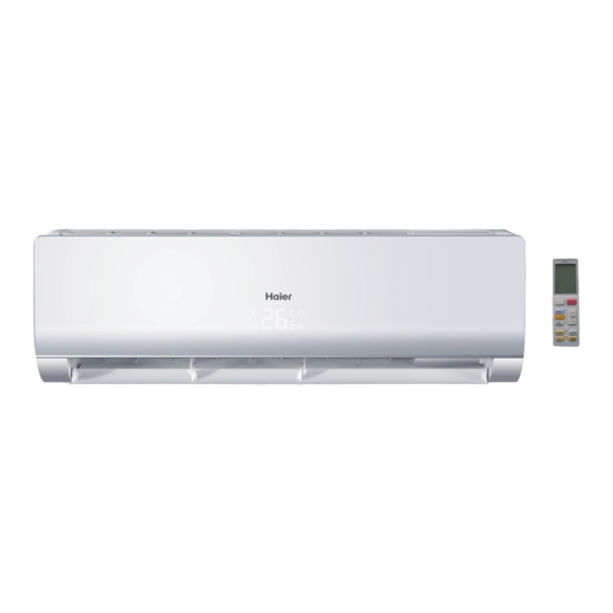
AS09NS1HRA-GOLDEN
AS09NS1HRA-GREY
AS09NS1HRA-WHITE
WARNING
2013 (Qingdao Haier Air Conditioner General corp. , Ltd)
All rights reserved. Unauthorized copying and distribution is a violation of law
Version V1
Date 2013-11-25
Advertisement
Table of Contents

Related Manuals for Haier AS09NS1HRA-GOLDEN


Summary of Contents for Haier AS09NS1HRA-GOLDEN
- Page 1 Repair the product or products dealt with in this service information by anyone else could result in serious injury or death 2013 (Qingdao Haier Air Conditioner General corp. , Ltd) All rights reserved. Unauthorized copying and distribution is a violation of law...
-
Page 2: Table Of Contents
Table fo contents Contents 1. Introduction .................... 1 2. Features ....................7 3. Specifications ..................8 4. Sensors list.................... 9 5. Piping diagrams ..................10 6. Printed Circuit Board Connector Wiring Diagram........11 7. Functions and Control ................8. System configuration................9. Dimensional drawings ................10. -
Page 3: Introduction
Intuoduction 1 Introduction 1.1 Model name explanation Apply toT1; 220~240V50HZ/1ph DC inverter Indoor units Version number 35N Platform Platform of indoor units: N (N platform) Nominal cooling capacity (9000BTU/h) Type of indoor unit: S (wall-mounted) Indoor unit Domestic air conditioner... - Page 4 Intuoduction 1.2 Safety Cautions Be sure to read the following safety cautions before conducting repair work. The caution items are classified into “Warning” and “Caution”. The “Warning” items are especially important since they can lead to death or serious injury if they are not followed closely. The “Caution” items can also lead to serious accidents under some conditions if they are not followed.
- Page 5 Intuoduction Warning Do not repair the electrical components with wet hands . Working on the equipment with wet hands can cause an electrical shock Do not clean the air conditioner by splashing water. Washing the unit with water can cause an electrical shock.
- Page 6 Intuoduction Warning Be sure to use an exclusive power circuit for the equipment, and follow the technical standards related to the electrical equipment, the internal wiring regulations and the instruction manual for installation when conducting electrical work. Insufficient power circuit capacity and improper electrical work can cause an electrical shock or fire. Be sure to use the specified cable to connect between the indoor and outdoor units.
- Page 7 Intuoduction Caution Installation of a leakage breaker is necessary in some cases depending on the conditions of the installation site, to prevent electrical shocks. Do not install the equipment in a place where there is a possibility of combustible gas leaks. If a combustible gas leaks and remains around the unit, it can cause a fire.
- Page 8 Intuoduction Caution Check to see if the parts and wires are mounted and connected properly, and if the connections at the soldered or crimped terminals are secure. Improper installation and connections can cause excessive heat generation, fire or an electrical shock. If the installation platform or frame has corroded, replace it.
-
Page 9: Features
Specifications 2.Features Super quiet: Lower noise operation condition A-PAM DC inverter:With adoption of S-TYPE,S-PAM and PHASE control technology to works more stably at low-frequency,and is more energy-saving,mor powerful at high frequency. Long distance air supplying: Heating: When -15 can still heating natural heating maintenance:Heating Holding 10 temperature Confortable sleep The setting temperature and the indoor noise can be adjusted to a more comfortable... -
Page 10: Specifications
Specifications 3 Specifications NOMINAL DISTRIBUTION SYSTEM VOLTAGE NOMINAL CAPACITY and NOMINAL INPUT n i l Capacity rated Btu/h 9210 9550 0.71 0.68 ³ 1.2*10 ³ TECHNICAL SPECIFICATIONS Dimensions H*W*D 855*204*280 Packaged Dimensions Golden/Grey/White Sound 39/33/26/23 38/33/26/22 dB(A) peessure(Hi/Mid/Lo/So) Sound level Sound power(high) Domestic air conditioner... -
Page 11: Sensors List
Specifications TECHNICAL SPECIFICATIONS-PARTS cooling heating Air flow rate(high) m³/h Speed(super/high/low) 1050/950/650 950/900/630 Type ML fin- 7HI-HX tube Heat exchanger c t i Air filter Removable/Washable/Mildew Proof Temperature control Microcomputer Control l l o Note: the data are based on the conditions shown in the table below Conversation formulae cooling heating... -
Page 12: Piping Diagrams
Piping diagrams 5 Pinping diagrams Domestic air conditioner... -
Page 13: Printed Circuit Board Connector Wiring Diagram
Connector Wiring diagrams 6. Printed Circuit Board Connector Wiring Diagram Connectors series PCB connector Connect with load Connector for fan motor Connector for heat exchanger thermistor and Room temperature thermistor Connector for UP&DOWN STEP motor CN10 Connector for L&R STEP motor CN11 CON21 Connector for power N wire... - Page 14 Connector Wiring diagrams CN10 CN36 CN34 CN51 CN11 CN23 CN52 CON2 CON1 CON3 CN21 Domestic air conditioner...
- Page 15 Connector Wiring diagrams DC FAN MOTOR Fresh air up-down stepmoter left stepmoter EMERGENCY SWITCH Room card RECEIVER DISPLAY AMBIENT TEMP SENSOR PIPING TEMP SENSOR Right stepmoter Domestic air conditioner...
-
Page 16: Functions And Control
Functions and Control 7.Funcitions and Control 7.1 Main functions and control specification 7.1.1 Automatic operation When the running mode is turned to automation after starting the system, the system will first determine the running mode according to the current room temperature and then will run according to the determined mode. - Page 17 Functions and Control 7.1.3 Dehumidifying mode. * temperature control range: 16---30 * temperature difference: Control feature: send the dehumidifying signal to the outdoor system. When Tr>Ts+2 , the compressor will be turned on, the indoor fan will operate at the set speed. When Tr is between the Ts and Ts+2 , the outdoor system will operate at the high dehumidifying frequency for 10 minutes and then at the low dehumidifying mode for six minutes.
- Page 18 Functions and Control *Indoor fan control manual control: You can choose high, medium, low and automatic speed control. Automatic: When Tr<Ts, high speed. When Ts Tr Ts+2 , medium speed. When Tr> Ts+2 , low speed. When the airflow speed has no delay from the high to low switching, the speed should be delayed for 3 minutes (remain at high speed for 3 minutes.) before the next switch.
- Page 19 Functions and Control mode, the cooling strength/ mute function will be offered; if the system enters the heating mode, then the heating strength/ mute function will be offered; if the system enters the airflow mode, there will be no strength/ mute function. 7.1.6 Mute operation The system enters the mode after receiving the ‘mute signal’.
- Page 20 Functions and Control keys, the timing of the 8 hours dormancy will take the first timing as the start time, any presses on other keys will not affect the original timing. 2.4 Indoor fan control under the dormant operation. If the indoor fan is at the high speed before the dormant operation setting, the speed will be turned to medium after the setting.
- Page 21 Functions and Control and will not be revealed. 7.1.13 Abnormal operation of indoor system When the outdoor system operates, if the indoor system operation differs from the outdoor system, the abnormal operation malfunction will be reported. 10s after the report, the indoor system will be closed. Outdoor system mode Indoor system mode conflicts...
- Page 22 Functions and Control according to the set mode and neglect the communication signals of the outdoor system. However, it has to send signals to the outdoor system. * Quitting condition: This mode can be quitted after receiving the quitting signal from the remote control or urgency system.
- Page 23 Functions and Control 7.1.20 Time cutting function: Connect the test program terminal on the mainboard after connecting the system to the power circuit. The CPU of the main control will be 60 times faster. 7.2 Value of thermistor Room sensor and Pipe Sensor R25 =10K B25 /50 =3700K 3% Temp.(( ))
- Page 24 Functions and Control 29.2545 27.5519 25.9250 -1.29 1.24 27.8708 26.2858 24.7686 -1.27 1.22 26.5605 25.0851 23.6704 -1.25 1.20 25.3193 23.9462 22.6273 -1.23 1.18 24.1432 22.8656 21.6361 -1.20 1.16 23.0284 21.8398 20.6939 -1.18 1.14 21.9714 20.8659 19.7982 -1.15 1.12 20.9688 19.9409 18.9463 -1.13 1.09...
- Page 25 Functions and Control 4.8400 4.5905 4.3500 -1.49 1.44 4.6708 4.4252 4.1887 -1.53 1.47 4.5083 4.2666 4.0342 -1.57 1.51 4.3524 4.1145 3.8862 -1.61 1.55 4.2026 3.9686 3.7443 -1.65 1.59 4.0588 3.8287 3.6084 -1.70 1.62 3.9206 3.6943 3.4780 -1.74 1.66 3.7878 3.5654 3.3531 -1.78 1.70...
- Page 26 Functions and Control 1.2226 1.1113 1.0092 -3.48 3.19 1.1880 1.0789 0.9789 -3.53 3.24 1.1546 1.0476 0.9497 -3.58 3.28 1.1223 1.0174 0.9215 -3.64 3.33 1.0910 0.9882 0.8942 -3.69 3.37 1.0607 0.9599 0.8679 -3.74 3.42 1.0314 0.9326 0.8424 -3.80 3.46 1.0030 0.9061 0.8179 -3.85 3.51...
-
Page 27: System Configuration
System configuration 8 System configuration 8.1System configuration After the installation and test operation of the room air conditioner have been completed, it should be operated and handled as described below. Every user would like to know the correct method of operation of the room air conditioner, to check if it is capable of cooling(or heating) well, and to know a clever method of using it. - Page 28 System configuration Parts and Functions Indoor Unit Outdoor Unit Air Purifying Filter (inside) Inlet Emergency Inlet grille Switch Outlet Anion generator Horizontal flap CONNECTING PIPING OUTLET (inside) (adjust up and down air flow AND ELECTRICAL WIRING Don't adjust it manually) Vertical blade INLET DRAIN HOSE...
- Page 29 System configuration Operation Inner side of the controller Load the batteries as illustrated. 2 R-03 batteries, resetting key (cylinder); Be sure that the loading is the panel display “01”, the in line with the “+”/“-”; operating power is 100W; SMART when the panel display SET TEMP.
- Page 30 System configuration Operation COOL,HEAT and DRY Operation QUIET Operation Unit start. Select operation mode. SOFT QUIET QUIET QUIET Press the COOL button on QUIET Operation the remote control. When COOL appears on the remote control, the display board will turn BLUE. SPEED SPEED Press the HEAT button on the remote control.
- Page 31 System configuration Operation Press TEMP button. Every time the button is pressed, temp. setting increases 0.5 ºC. Every time the button is For each press of “ ” button, air pressed, temp. setting decreases 0.5 ºC. displays as follows according to different operation modes: QUIET QUIET...
- Page 32 System configuration Operation HEALTH Operation HEALTH AIRFLOW Operation The setting of The water-ion generator in the airconditioner can generate a lot function of anion effectively balance the quantity of position and anion in the air and also to kill bacteria appears on the display.
- Page 33 System configuration Operation POWER Operation TIMER Operation Set Clock correctly before starting Timer operation. You can let unit start or stop automatically a following times: Before you wake up in the morning, or get back from outside or after you fall asleep at night. Select your desired operation POWER Operation mode.
- Page 34 System configuration Operation Comfortable SLEEP 3 hours then stops. Temp. is lower than temp. setting so that room temperature won’t be too high for your Before going to bed, you can simply press the SLEEP sleep. button and unit will operate in SLEEP mode and bring you a sound sleep.
- Page 35 System configuration Operation SMART Operation ECO Operation Automatic adjusting with the environmental temperature, (This function is unavailable on running with power saving. some models) SMART One key can give you a comfortable room! The air conditioning unit can AUTO judge the indoor temperature and Press ECONOMY button “...
- Page 36 System configuration Operation FRESH Operation Emergency operation and test operation Exhaust the vitiated air from the room, and inhale fresh air. Emergency Operation: (This function is unavailable on some models.) Use this operation only when the remote controller is defective or lost, and with function of emergency running, air conditoner can run automatically for a while.
- Page 37 System configuration IMPORTANT INFORMATION REGA- EUROPEAN REGULATIONS RDING THE REFRIGERANT USED CONFORMITY FOR THE MODELS Contains fluorinated greenhouse gases covered by the Kyoto Protocol All the products are in conformity with the following R410A European provision: - Low Voltage Directive 2006/95/EC -Electomagnetic CompatibilitY 2004/108/EC 1+2= ROHS...
- Page 38 System configuration Indoor Unit Installaion Necessary Tools for Installation Power Source Torque wrench Driver Before inserting power into receptacle, check the voltage without (17mm,22mm,26mm) Nipper fail. Pipe cutter Hacksaw The power supply is the same as the corresponding nameplate. Flaring tool Hole core drill Install an exclusive branch circuit of the power.
- Page 39 System configuration Indoor Unit Installation [ Left Left-rear piping ] Fitting of the Mounting Plate and Positioning of the wall Hole In case of left side piping, cut away, with a nipper, the lid for left piping. In case of left-rear piping, bend the pipes according to the piping When the mounting plate is first fixed direction to the mark of hole for left-rear piping which is marked on heat insulation materials.
- Page 40 System configuration Correct Incorrect When connecting the cable after installing the indoor unit 1. Insert from outside the room cable into left side of the wall Lean Damage of ?are Crack Partial Too outside hole, in which the pipe has already existed. 2.
- Page 41 System configuration Maintenance For Smart Use of The Air Conditioner Remote Controller Indoor Body Setting of proper room Do not block the air inlet temperature or outlet Proper wipe the air conditioner by using a temperature soft and dry cloth.For serious stains, use a neutral detergent diluted with Do not usewater,wipe the controller water.Wring the water out of the...
-
Page 42: Dimensional Drawings
Seivice diagnosis 9.Dimensional drawings 10.Center of gravity Domestic air conditioner... -
Page 43: Service Diagnosis
Seivice diagnosis 11 Service Diagnosis 11.1 Caution for Diagnosis The operation lamp flashes when any of the following errors is detected. 1. When a protection device of the indoor or outdoor unit is activated or when the thermistor malfunctions, disabling equipment operation. 2. - Page 44 Service diagnosis Code indication Indoor Reference Outdoor fault description displaying Page (LED1 flash panel code times) indication Indoor and Communication fault between indoor and Page53. Outdoor outdoor units Room temperature sensor failure Page43. Indoor Malfunction Heat-exchange sensor failure Page43. Indoor fan motor malfunction Page44.
- Page 45 Installations 11.4.1 Thermistor or Related Abnormality E1: Room temperature sensor failure Indoor display E2: Heat-exchange sensor failure LED1 flash 10 times Defrost temperature sensor failure LED1 flash 11 times Suction temperature sensor failure Outdoor display LED1 flash 12 times Ambient temperature sensor failure LED1 flash 13 times Discharge temperature sensor failure Method of The temperatures detected by the thermistors are used to determine thermistor errors...
- Page 46 Installations 11.4.2 EEPROM abnormal Indoor Display E4: indoor EEPROM error outdoor display F12: Outdoor EEPROM error; Outdoor LED1 flash 1 times Method of The Data detected by the EEPROM are used to determine MCU malfunction detection Malfunction detection when the data of EEPROM is error or the EEPROM is damaged conditions Faulty EEPROM data Supposed causes...
- Page 47 Installations 11.4.3 Indoor AC fan motor malfunction Indoor Display The fan speed detected by the Hall IC during fan motor running which is used to Method of determine the fan motor operating malfunction detection Malfunction detection When there is no fan speed feedback signal within 2 minutes conditions Operation halt due to breaking of wire inside the fan motor.
- Page 48 Installations 11.4.4 Outdoor DC fan motor fault Outdoor diplay LED1 flash 9 times Method of DC fan motor is detected by checking the fan running condition and so on malfunction detection Malfunction detection when the data of EEPROM is error or the EEPROM is damaged conditions DC fan motor protection dues to the DC fan motor faulty Supposed causes...
- Page 49 Installations Check whether Terminal on the outdoor mainboard is well inserted. Reinsert the terminals Is it normal? Electrify the machine again and turn it on in the Cool state with the remote controller. check whether motor can Measure the voltage between 1 and 3 of the terminal of fan motor on the mainboard about DC310V, Measure the voltage between 3 and 4 of the terminal about DC15V.
- Page 50 Installations 11.4.5 IPM protection Outdoor diplay LED1 flash 2 times Method of IPM protection is detected by checking the compressor running condition and so on malfunction detection Malfunction detection The system leads to IPM protection due to over current conditions The compressor faulty leads to IPM protection circuit component of IPM is broken and led to IPM protection Supposed causes...
- Page 51 Installations 11.4.6 Over-current of the compressor LED1 flash 3 or 24 or 25 times Outdoor diplay Method of he current of the compressor is too high malfunction detection Malfunction detection when the IPM Module is damaged or the compressor is damaged. power supply conditions voltage is too low or too high...
- Page 52 Installations 11.4.7 The communication fault between IPM and outdoor PCB Outdoor diplay LED1 flash 4 times Method of Communication is detected by checking the IPM module and the outdoor PCB malfunction detection The outdoor PCB broken leads to communication fault Malfunction detection conditions The IPM module broken leads to communication fault...
- Page 53 Installations 11.4.8 Power Supply Over or under voltage fault Outdoor diplay LED1 flash 21 times The power supply is over voltage Method of An abnormal voltage rise or fall is detected by checking the specified voltage detection malfunction detection An voltage signal is fed from the voltage detection circuit to the microcomputer Malfunction detection conditions Supply voltage not as specified.
- Page 54 Installations 11.4.9 Overheat Protection For Discharge Temperature Outdoor diplay LED1 flash 8 times Method of The Discharge temperature control is checked with the temperature being detected by malfunction detection the Discharge pipe thermistor Malfunction detection when the compressor discharge temperature is above 110 conditions Electronic expansion valve defective Supposed causes...
- Page 55 Installations 11.4.10 The communication fault between indoor and outdoor indoor diplay Outdoor diplay LED1 flash 15 times Method of Communication is detected by checking the indoor PCB and the outdoor PCB malfunction detection The outdoor PCB broken leads to communication fault Malfunction detection The indoor PCB broken leads to communication fault conditions...
- Page 56 Installations Check the indoor mainboard. Measure the voltage between Jumpers 3 and 4 of IC1 on the indoor mainboard with a multimeter. Test the outdoor power supply (230VAC and +310VDC) with a multimeter. If the voltage is of a constant value of 0V DCto5V DC If 230VAC is available but 310DC not, the power module is damaged, replace it...
- Page 57 Table of Contents 11.4.11 Loss of synchronism detection Inverter side current detection is abnormal Outdoor diplay LED1 flash 18 times LED1 flash 19 times The position of the compressor rotor can not detected normally Method of malfunction detection when the wiring of compressor is wrong or the connection is poor; or the compressor Malfunction detection is damaged conditions...
- Page 58 Table of Contents 11.4.12 High work-intense protection LED1 flash 21 times Outdoor diplay Method of High work-intense control is activated in the heating mode if the temperature being malfunction detection sensed by the heat exchanger thermistor exceeds the limit. Activated when the temperature being sensed by the heat exchanger rises above Malfunction detection conditions twice in 30 minutes.
-
Page 59: Circuit Diagrams
Circuit diagrams 12. Circuit diagrams +12V FLZ1 HXF1 TEST 25/35 +12V MODE EEPROM C1 8 100n F ROOM SRCK PIPE DIGH DIGL MODE KI1/AN9/P11 KI2/AN10/P12 P33/SSI DIG_MODE KI3/AN11/P13 P34/SDA/SCS DIGL COM3 MODE (INT2)/P32 MODE DIGH COM2 (INT1)/P36 P43/XCIN +12V TAO/P30 P44/XCOUT TBO/P31 RESET... - Page 60 Circuit diagrams Sincere Forever Haier Generalny Dystrybutor Haier AC w Polsce Refsystem sp. z o.o. ul. Metalowców 5 86-300 Grudziądz tel. +48 22 110 00 19 email: haier@refsystem.pl www.haier-ac.pl Domestic air conditioner...
Need help?
Do you have a question about the AS09NS1HRA-GOLDEN and is the answer not in the manual?
Questions and answers