Sign In
Upload
Manuals
Brands
IBM Manuals
Storage
SAN128B-7
IBM SAN128B-7 Manuals
Manuals and User Guides for IBM SAN128B-7. We have
1
IBM SAN128B-7 manual available for free PDF download: Installation, Service And User Manual
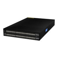
IBM SAN128B-7 Installation, Service And User Manual (114 pages)
Storage Networking
Brand:
IBM
| Category:
Storage
| Size: 4 MB
Table of Contents
Table of Contents
3
Figures
6
Accessibility Features
9
Getting Help
9
Read this First
9
How to Send Your Comments
10
Caution Notices
11
Safety and Environmental Notices
11
Safety Notices and Labels
11
Danger Notices
13
General Precautions
15
Safety Labels
15
ESD Precautions
16
Power Precautions
17
Attention Notices
18
Laser Precautions
18
Lifting and Weight-Related Precautions
18
ESD Precautions
19
Rack Installation
19
Rack Safety
19
Rack Relocation (19" Rack)
20
Product Recycling and Disposal
21
Brocade Documents
22
IBM and Brocade Product Matrix
22
Preface
22
Product Documentation
22
Chapter 1. Device Overview
25
License Options
26
Port-Side View
26
Nonport-Side View
27
Device Management Options
27
Nonport-Side View with AC Power Supply and Fan Assembly Units
27
Chapter 2. Preparing for the Installation
29
Safety Precautions
29
Facility Requirements
29
Quick Installation Checklist
30
Facility Requirements
30
Installation and Basic System Configuration
31
Shipping Carton Contents
33
Chapter 3. Mounting the Switch
34
Precautions Specific to Mounting
34
Standalone Installation
34
Installing the Universal Four-Post Rack Kit
35
Time and Items Required
35
Parts List
36
Rack Kit Parts
36
Flush-Front Mounting
37
Attaching the Bracket Extensions to the Device
39
Positioning the Device in the Rack
40
Attaching the Rear Brackets to the Extensions
41
Flush-Rear (Recessed) Mounting
42
Attaching the Rear Brackets to the Rack Posts
42
Attaching the Front Brackets to the Rear of the Device
43
Attaching the Bracket Extensions to the Device
44
Positioning the Device in the Rack
45
Attaching the Rear Brackets to the Extensions at the Front of the Device
45
Installing the Universal Two-Post Rack Kit
48
Time and Items Required
48
Attaching the Rear Brackets to the Front Rack Posts
48
Parts List
49
Flush-Front Mounting
49
Rack Kit Parts
49
Attaching Front Brackets to a Rack
51
Attaching the Rear Brackets to a Rack
52
MID-Mounting
53
Attaching the Front Brackets
54
Attaching Front Brackets to a Rack
55
Attaching the Rear Brackets to a Rack
56
Attaching the Rear Brackets to the Device
56
Attaching the Rear Brackets to the Device
57
Chapter 4. Initial Setup and Verification
58
Items Required
58
Providing Power to the Device
58
Establishing a First-Time Serial Connection
58
Configuring the IP Address
59
Using DHCP to Set the IP Address
60
Setting a Static IP Address
60
Setting the Date and Time
60
Setting the Time Zone
61
Synchronizing Local Time with an External Source
61
Customizing the Chassis Name and Switch Name
62
Establishing an Ethernet Connection
62
Setting the Domain ID
62
Verifying Correct Operation
63
Backing up the Configuration
64
Powering down the Device
64
Chapter 5. Installing Transceivers and Cables
65
Time and Items Required
65
Precautions Specific to Transceivers and Cables
65
Cleaning the Fiber-Optic Connectors
65
Optical Transceiver Extraction Tool
65
Managing Cables
66
Installing an SFP+ Transceiver
66
Replacing an SFP+ Transceiver
68
Installing an SFP-DD Transceiver
68
Replacing a SFP-DD Transceiver
70
Installing an SFP-DD Connector
70
Verifying the Operation of New Transceivers
71
Chapter 6. Monitoring the Device
72
Interpreting Port-Side Leds
72
System Power LED
73
System Status LED
73
System Power LED Patterns During Normal Operation
73
System Status LED Patterns During Normal Operation
73
FC Port Status LED
74
FC Port (SFP-DD) Status Leds
74
Nonport-Side LED Locations
75
Power Supply Leds
76
Nonport-Side LED Patterns During Normal Operation
76
Fan Assembly Status LED
77
Interpreting the POST Results
77
Fan Assembly Status LED Patterns During Normal Operation
77
Interpreting the BOOT Results
78
Running Diagnostic Tests
78
Chapter 7. Power Supply Assemblies
79
Precautions Specific to the Power Supply Assemblies
79
Identifying the Airflow Direction
80
Power Supply Assembly Unit Fault Indicators
81
Power Supply Assembly Task Guide
81
Time and Items Required
82
Recording Power Supply Assembly Critical Information
82
Removing a Power Supply Assembly
82
Inserting a New Power Supply Assembly
83
Removing a Power Supply Assembly
83
Verifying the Operation of the Power Supply and Fan Assemblies
84
Chapter 8. Fan Assemblies
85
Fan Assembly
85
Precautions Specific to the Fan Assemblies
86
Identifying the Airflow Direction
86
Fan Assembly Unit Fault Indicators
87
Fan Assembly Task Guide
87
Time and Items Required
87
Recording Fan Assembly Critical Information
88
Removing a Fan Assembly
88
Inserting a New Fan Assembly
88
Verifying the Operation of the Power Supply and Fan Assemblies
89
Chapter 9. Chassis Replacement
90
Customer Replacement Responsibilities
90
Determining the Need to Replace the Chassis
90
Chassis Replacement Overview
91
Reconnecting System to the Network and Fabric
95
Downloading the Configuration
95
Verifying Correct Operation of System
96
Verifying Correct Configuration of the Fabric
97
IBM Service Replacement Responsibilities
98
Disconnecting the Cables
98
Remove the Old Switch Chassis and Install the New Switch Chassis
98
Appendix A. Product Specifications
99
Appendix B. Cable Routing Table
105
Notices
107
Trademarks
108
Homologation Statement
108
Electronic Emission Notices
108
Federal Communications Commission Statement
108
Industry Canada Compliance Statement
108
Australia and New Zealand Class a Statement
109
European Union Electromagnetic Compatibility Directive
109
Germany Electromagnetic Compatibility Directive
109
People's Republic of China Class a Statement
110
Taiwan Class a Statement
111
Taiwan Contact Information
111
Japan Voluntary Control Council for Interference Class a Statement
111
Japan Electronics and Information Technology Industries Association Statement
111
Korean Communications Commission Class a Statement
112
Russia Electromagnetic Interference Class a Statement
112
Index
113
Advertisement
Advertisement
Related Products
IBM SAN192C-6
IBM SAN04B-R - System Storage Router
IBM SAN768B-2
IBM SAN384B-2
IBM SAN32B-E4
IBM SAN768B
IBM SAN42B-R
IBM SAN768C-6
IBM SAN50C-R
IBM TotalStorage SAN256N Director 2045-N16
IBM Categories
Server
Desktop
Storage
Laptop
Monitor
More IBM Manuals
Login
Sign In
OR
Sign in with Facebook
Sign in with Google
Upload manual
Upload from disk
Upload from URL