Table of Contents
Advertisement
Available languages
Available languages
Quick Links
Advertisement
Table of Contents

Related Manuals for VINCENT SV-237MKII


Summary of Contents for VINCENT SV-237MKII
- Page 1 Bedienungsanleitung deutsch Instructions for use english Manuel d‘utilisation français SV-237MKII Hybrid-Stereovollverstärker mit Class-A-Schaltung Integrated Hybrid Class A Stereo Amplifier Amplificateur hybride intégré stéréo classe A...
- Page 2 à la garantie ou pour les réparations après la période de garantie. Dans tous les cas, vos expériences avec les produits Vincent l‘intéressent, n‘hésitez pas à lui en faire part. Nous vous souhaitons beaucoup de plaisir avec notre / votre produit.
-
Page 3: Table Of Contents
INHALTSVERZEICHNIS/CONTENTS/SOMMAIRE Sicherheitshinweise Weitere Hinweise Lieferumfang Beschreibung des Gerätes Fernbedienung Installation Bedienung des Gerätes Weitere Tipps Fehlersuche Technische Daten Lexikon/Wissenswertes deutsch Safety guidelines Other instructions Included in delivery Description of the appliance Remote control Installation Operating the appliance Tips Search for errors Technical Specifications Glossary english... -
Page 4: Sicherheitshinweise
Händen an. Verwenden Sie das Hörschäden vermieden werden. Damit Sie sich im Lieferumfang enthaltene oder andere Netzkabel nicht unbeabsichtigt hoher Lautstärke aussetzen, von Vincent. stellen Sie vor dem Wechsel des Eingangskanals Ausschalten stets einen niedrigen Wert ein. -
Page 5: Weitere Hinweise
Aufstellen des Gerätes Sintron Distribution GmbH, 76473 Iffezheim. Die Art der Aufstellung der Anlage hat Vincent arbeitet ständig an der Verbesserung und klangliche Auswirkungen. Stellen Sie diese deshalb Weiterentwicklung seiner Produkte. Deshalb blei- nur auf eine dafür geeignete, stabile Unterlage. -
Page 6: Lieferumfang
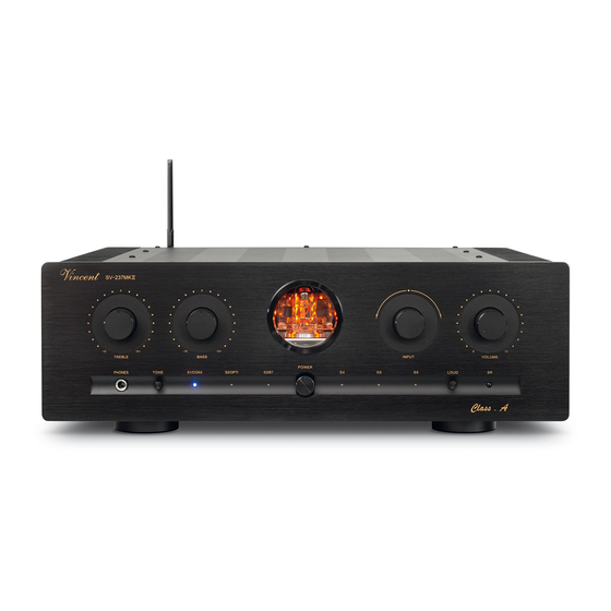
LIEFERUMFANG Bitte prüfen Sie den Inhalt der Verpackung, diese sollte zusätzlich zum Gerät folgendes Zubehör enthalten: • 1 Netzkabel • 1 Fernbedienung VRC-12 • dieses Handbuch BESCHREIBUNG DES GERÄTES Unter der Leitung von Frank Blöhbaum, wurde das eine höhere spektrale Reinheit des Signals was Schaltungskonzept komplett überarbeitet und ver- eine nochmals verbesserte Feinzeichnung im bessert. - Page 7 VORDERANSICHT 1. TREBLE: Höhenregler 8. Empfängerdiode für die Fernbedie- Zur Einstellung der Höhenanteile des Klangs. nung 2. BASS: Tiefenregler 9. POWER: Netzschalter Zur Einstellung der Bassanteile des Klangs. Schaltet das Gerät ein und aus. Im ausgeschalte- ten Zustand ist das Gerät vom Stromnetz getrennt. 3.
- Page 8 RÜCKANSICHT...
- Page 9 RÜCKANSICHT 12. REC OUT: Aufnahmeausgang 18. POWER CONTROL (12V) OUTPUT Schließen Sie hier, wenn gewünscht, z.B. ein Über diese Klinkenbuchsen (3,5 mm) werden die Aufnahmegerät an. Das Stereo-Signal dieses Signale zur Einschaltsteuerung (Trigger) ausgege- Ausgangs ist mit dem Ausgangssignal der mo- ben.
-
Page 10: Fernbedienung
FERNBEDIENUNG Richten Sie die Fernbedienung mit deren Vor- Achten Sie darauf, dass Sie die Fernbedienung derseite direkt auf die Gerätefront, zwischen nicht schräg auf das Gerät richten, außerhalb ei- Fernbedienung und Gerät dürfen sich keine nes Winkels von ±30° zur Mittelachse reagiert das Gegenstände befinden. - Page 11 TASTEN DER FERNBEDIENUNG 22. MUTE: Taste für die Stummschaltung Diese Taste schaltet die Lautsprecher sowie die Ausgangssignale von Aufnahmeausgang „REC OUT“ (12) und Vorstufenausgang „PRE OUT“ (13) 23. Eingangswahltasten Wählen Sie hiermit die Musikquelle, die Sie hören möchten. 24. DIMMER: Helligkeitseinstellung für die Beleuchtung des Röhrenfensters (3) an der Gerätevorderseite.
-
Page 12: Installation
Fall zur Beschädigung der Geräte füh- zuschöpfen, sollten nur hochwertige Lautsprecher- ren. Nehmen Sie deshalb niemals Änderungen an den Kabelverbindungen vor, während die Geräte und Verbindungskabel, beispielsweise Vincent eingeschaltet sind! Kabel, verwendet werden. Bevorzugen Sie geschirmte Audio-Kabel. Ihr Fachhändler wird Lautsprecheranschluss Sie gern diesbezüglich beraten. - Page 13 ANSCHLUSS DER QUELLGERÄTE Verbinden Sie die Ausgänge der Quellgeräte mit den Eingängen „INPUT“ (14) dieses Verstärkers. Meist sind die Ausgangsanschlüsse der Quellgeräte mit „LINE OUT“, „AUDIO OUT“ oder „FRONT OUT“ markiert. Informationen über die Anschlussmöglichkeiten der Quellgeräte finden Sie in deren Bedienungsanleitungen.
- Page 14 Stereo-Musikwiedergabe, eventuell auch in einem anderen Raum, verwendet werden sollen. Diese Lautsprecher werden dann an die Ausgänge zusätzlicher Endverstärker angeschlossen. Die Aus- gangsanschlüsse „PRE OUT“ (13) des SV-237MKII werden mit den Eingangsanschlüssen der Endstufe(n), welche meist mit „INPUT“, „POWER AMP IN“ oder „MAIN INPUT“ beschriftet sind, verbunden.
- Page 15 ANSCHLUSS DER QUELLGERÄTE ÜBER OPTICAL IN UND COAXIAL IN Der integrierte D/A-Wandler ermöglicht es ebenfalls digitale Tonsignale über ein optisches bzw. coaxiales Kabel zu empfangen und analog an den Verstärker weiter zu leiten. Hierzu dienen die Anschlüsse “Op- tical IN” und “Coaxial IN” (15) als Eingang. Digitaltonquelle mit optischer Signalverbindung Optisches Digitalkabel SV-237 MK II...
- Page 16 KABELVERBINDUNGEN FÜR DIE EINSCHALTSTEUERUNG (POWER CONTROL) Viele AV-Systeme bestehen aus einer Vielzahl von Einzelkomponenten. Um diese nicht vor und nach jedem Gebrauch alle einzeln aus- und einzuschalten, haben manche Hersteller die Geräte mit einer sogenannten „POWER CONTROL“-Schaltung, auch „TRIGGER“ oder „Einschaltsteuerung“ genannt, ausgestattet.
- Page 17 KABELVERBINDUNGEN FÜR DIE EINSCHALTSTEUERUNG (POWER CONTROL) SV-237 MK II z.B. CD-Player Power-Control-Kabel z.B. Endverstärker Viele der Geräte, welche durch ein Schaltsignal gesteuert werden können (nicht Vorverstärker oder Vollverstärker), besitzen zwei Anschlussbuchsen, welche nicht als Ein- oder Ausgang gekennzeichnet sind. In diesem Fall kann einer der beiden beliebig ge- wählt werden.
- Page 18 ANSCHLUSS DER LAUTSPRECHER An den Verstärker SV-237MKII können entweder ein Lautsprecherpaar oder auch zwei Lautsprecherpaare angeschlossen werden. Beide Ausgänge bekommen dasselbe Stereosignal. Für jeden Lautsprecher finden Sie am Gerät zwei Lautsprecherklemmen (positiv + und negativ –), welche mit einer Seite eines Lautspre- cherkabels verbunden werden.
- Page 19 ANSCHLUSS DER LAUTSPRECHER Wenn Sie konfektionierte Lautsprecherkabel mit 4 mm Bananensteckern verwenden, brauchen Sie nur die zwei Stecker eines jeden Lautsprecherkabels mit den zwei zugehörigen Klemmen zu verbinden. Die Schraubkappe der Klemme sollte im Uhrzeigersinn festgedreht werden. Sollen Kabelschuhe verwendet werden, muss an jeder Klemme der Schraubkopf im Gegenuhrzeigersinn gelöst, der Kabelschuh daruntergeschoben und die Schraubkappe im Uhrzeigersinn festgedreht werden.
- Page 20 ANSCHLUSS DES NETZKABELS Prüfen Sie, ob die Stromversorgung Ihres Haushalts für das Gerät geeignet ist. Benötigte Spannung und Frequenz sind auf der Geräterückseite neben der Netzbuchse abzulesen. Wenn die Stromversorgung geeignet ist, drücken Sie den Kaltgerätestecker des mitgelieferten Netzkabels fest in die Netzbuchse an der Geräterückwand.
-
Page 21: Bedienung Des Gerätes
BEDIENUNG DES GERÄTES Aktion Taste(n) Beschreibung Das Gerät wird an der Gerätevorderseite ein- und ausgeschaltet. Ist der Schalter in der Ausschaltposition, ist das Gerät vom Stromnetz getrennt. Das Gerät besitzt keine Funktion der Betriebsbereitschaft POWER (8) Ein- und Ausschalten (Standby). Im eingeschalteten Zustand leuchtet eine der LEDs für die Eingangswahl (7), wenn das Gerät nicht stummgeschaltet ist. - Page 22 Bluetooth Geräten. Der SV-237 MKII wird in der Liste unter dem Namen „Vincent“ angezeigt. 4. Wählen Sie „Vincent“ aus und schließen den Kopplungsprozess ab. 5. Der SV-237 MKII ist nun mit Ihrem Smartphone, Tablet oder PC´s verbunden und Sie können die Musikwiedergabe starten.
-
Page 23: Weitere Tipps
WEITERE TIPPS Einspielzeit / Aufwärmen Eine weitere mögliche Quelle für Brummstörungen Ihre Audio-Geräte benötigen eine gewisse Zeit bis stellt die elektromagnetische Einstrahlung des Netz- sie ihre klangliche Höchstleistung erreichen. Dieser teiles anderer Geräte (z.B. Verstärker, Receiver, Zeitraum ist für die verschiedenen Komponenten CD-Player, Tuner usw.) auf das Tonabnehmersystem Ihres Systems sehr unterschiedlich. -
Page 24: Fehlersuche
FEHLERSUCHE Symptom Mögliche Fehlerursache Abhilfe Keine Funktion nach Netzkabel nicht an eine betriebsbereite Stellen Sie eine Verbindung zu einer funktio- Betätigung des Steckdose angeschlossen. nierenden Steckdose her. Netzschalters Netzkabel nicht fest in die Steckdose und Prüfen Sie das Netzkabel, tauschen Sie es die Gerätebuchse gesteckt oder defekt. - Page 25 FEHLERSUCHE Symptom Mögliche Fehlerursache Abhilfe Schlechte Tonqualität Anschlüsse der Kabelverbindungen haben Prüfen Sie die Audio-Anschlüsse. sich gelöst, die Anschlüsse sind verschmutzt oder ein Kabel defekt. Die Klangeinstellungen an den Knöpfen „TRE- Prüfen Sie die dort gewählten Einstellungen. BLE“oder „BASS“ sind nicht richtig gewählt. Schließen Sie eine Phonovorstufe im Ein Plattenspieler wurde ohne zwischenge- Signalweg zwischen Plattenspieler und...
-
Page 26: Technische Daten
TECHNISCHE DATEN Übertragung: 20 Hz - 20 kHz +/- 0,5 dB, 20 Hz - 50 kHz +/- 2 dB Leistung RMS / 8 Ohm: 2 x 150 Watt Leistung RMS / 4 Ohm: 2 x 250 Watt Leistung Class A / 8 Ohm: 2 x 10 Watt Klirrfaktor: <... -
Page 27: Lexikon/Wissenswertes
LEXIKON/WISSENSWERTES Audio-Quellen/Audio-Quellgeräte Pegel Komponenten Ihrer HiFi-Anlage und alle weiteren Eine Art der Darstellung jeder physikalischen Geräte, deren Ton Sie über das System hören Größe; gebräuchliches Maß für Signalspannungen möchten und dazu an den Vor-, Vollverstärker oder und Lautstärke. Wird in Dezibel (dB) angege- Receiver anschließen. -
Page 28: Safety Guidelines
Be careful with the volume setting, lead with wet or damp hands. Use the power cable supplied or another one from Vincent. therefore, in order to prevent damage to hearing. So that you do not expose yourself to high volumes... -
Page 29: Other Instructions
OTHER INSTRUCTIONS Setting up the appliance Vincent is a registered trademark of Sintron Distribution GmbH, 76473 Iffezheim. How the system is set up has an effect on the Vincent works continually to improve and develop sound quality. Therefore only place it on a suitable, its products. -
Page 30: Included In Delivery
INCLUDED IN DELIVERY Please check the contents of the packaging, which in addition to the appliance should contain the following accessories: • 1 power cable • 1 remote control VRC-12 • this manual DESCRIPTION OF THE APPLIANCE Under the direction of Frank Blöhbaum, the circuit Musicality and sound are significantly better than concept was completely revised and improved. - Page 31 FRONT VIEW 1. TREBLE 8. Infrared remote control receiver This is the knob for setting the treble proportions (high frequencies) of the sound. 9. POWER This is the main power switch for turning on and 2. BASS off the device. The amplifier is separated from the This is the knob for setting the bass proportions mains voltage when switched off and cannot be (low frequencies) of the sound.
- Page 32 REAR VIEW...
- Page 33 REAR VIEW 18. POWER CONTROL (12V) OUTPUT 12. REC OUT: recording output At these jack connectors the signals for the on/off If desired, you can connect a recording device like control (Power Control, Trigger) are emitted a CD recorder or a tape recorder to this output. The stereo signal of this output is identical to the output 19.
-
Page 34: Remote Control
REMOTE CONTROL Point the front of the remote control directly at Make sure that you do not point the remote control the front of the appliance, making sure there are at an angle to the appliance, as beyond an angle no objects between the remote control and the of ±30°... - Page 35 BUTTONS OF THE REMOTE CONTROL 22. MUTE Pressing this button once mutes the speakers, the recording output (12) and the preamplifier output (13). Pressing it again returns to the original volume. 23. Input selector buttons Select the input source you want to listen to with these buttons.
-
Page 36: Installation
To avoid this hazard, connect or disconnect only in tential, only high quality loudspeakers and connec- switched-off state and more than one minute after ting cables, for example Vincent cables, should be used. Your local dealer will be glad to advise you deactivating! about this. - Page 37 CONNECTION OF THE SOURCE EQUIPMENT Connect the outputs of the source devices with the inputs (14) of the amplifier. The output sockets on the source equipment are usually indicated by “Line Out”, “Audio Out” or “Front Out”. You will find information about ways to connect source equipment in their operating manuals.
- Page 38 CONNECTION OF A RECORDING DEVICE If you want, you can use the RCA sockets “REC OUT” (12) on the back of the appliance to connect an analogue stereo recording device (e.g. CD recorder, cassette recorder etc.) or another appliance that is intended for receiving the unchanged, fixed stereo output level (line level) from the signal source selected on the amplifier at any given time.
- Page 39 CONNECTION OF SOURCE DEVICES OVER OPTICAL IN AND COAXIAL IN The integrated D/A converter makes it possible to receive also digital audio signals via an optical and/ or coaxial cable and to transmit them analogously to the amplifier. Here, the “Optical IN” and “Coaxial IN”...
- Page 40 If you don‘t wish to use this function or if the other components do not support it, all you have to do is leave out these cable connections. The SV-237MKII is equipped with two output connectors for the power control. Here, the switching signal generated by the amplifier is available for other components of the system. Two HiFi components that are able to react to the power control signal can be connected directly to the amplifier‘s power...
- Page 41 CONNECTIONS FOR THE STANDBY CONTROL (POWER CONTROL) SV-237 MK II e.g. CD player power control cable e.g. main amplifier Many devices which can be controlled by a switching signal (not preamplifiers or integrated amplifiers), have two terminals which do not differentiate between input and output.
- Page 42 CONNECTION OF THE LOUDSPEAKERS Either a single pair of loudspeakers or two speaker pairs can be connected to the amplifier SV-237MKII. Both stereo outputs are identically provided with the signal of the currently selected input. For each loudspea- ker you will find two connector screws (positive + und negative –) at the amplifier‘s backside. One side of the speaker cable must be attached here.
- Page 43 CONNECTION OF THE LOUDSPEAKERS If you are using ready made loudspeaker cables with 4 mm banana plugs, all you need to do is connect the two plugs on each loudspeaker cable end to the two associated speaker connectors. Turn the connector screws clockwise to fasten them.
- Page 44 CONNECTION OF THE POWER CABLE Check whether the wall socket provides the appropriate mains power, which is the case if it is supplied with 230 V AC 50 Hz. Push the plug on the power cable supplied firmly into the power socket (17) on the back of the appliance.
-
Page 45: Operating The Appliance
OPERATING THE APPLIANCE Operation Button(s) Description The amplifier is switched on and off using this button at the front panel. It has no standby option. When switched off the device is internally separated from the AC power. The LED associated to the selected input Switch on and off POWER (9) channel (7) will be illuminated if the device is switched on and not... - Page 46 You will find the SV-237 MKII under the name „Vincent“ inside the list. 4. Please choose „Vincent“ und start the connection 5. The SV-237 MKII is connected to your smartphone, tablet or compu- ter and you can start the playpack.
-
Page 47: Tips
TIPS Burn in/ Warm up Your audio components need a certain time pe- audio inputs of the amplifier. Another possible riod until they reach maximum performance. The reason for humming noise is electromagnetic in- duration of this “warm up“ time is very different for terference of other components’, power supplies the various elements of your audio system. -
Page 48: Search For Errors
SEARCH FOR ERRORS Symptom Possible Cause Countermeasure Unit does not work Power cable is not connected to a suitable Connect to a functioning socket using a after pressing the wall outlet. suitable mains voltage. power button Power cable has not been firmly inserted into Check the power cable. - Page 49 SEARCH FOR ERRORS Symptom Possible Cause Countermeasure Poor sound quality The cable connections are not tight, the Check the cables and cable connections. connectors are knobs or a cable is defective. The tone settings on the knobs “TREBLE” or Check the settings selected there. “BASS”...
-
Page 50: Technical Specifications
TECHNICAL SPECIFICATIONS Frequency Response: 20 Hz - 20 kHz +/- 0,5 dB, 20 Hz - 50 kHz +/- 2 dB Nominal Output Power RMS / 8 Ohm: 2 x 150 Watt Nominal Output Power RMS / 4 Ohm: 2 x 250 Watt Nominal Output Power Class A / 8 Ohm: 2 x 10 Watt Harmonic Distortion:... -
Page 51: Glossary
GLOSSARY Audio Sources/Source devices Input sensitivity These are the components of your HiFi system Term for the smallest average (RMS) input voltage and all other appliances, whose sound you want which causes the maximum output power at the max- to hear over the system and are thus connected imum volume setting on the amplifier. -
Page 52: Consignes De Sécurité
Réglez le son sur une valeur mouillés ou humides. Utilisez le câble fourni ou un moindre avant de changer de canal d‘entrée pour autre câble de Vincent. ne pas être exposé sans le vouloir à une plus forte puissance sonore. -
Page 53: Autres Consignes
Il peut être modifié à tout moment nous vous recommandons de placer les appareils sans information préalable et n‘a pas valeur d‘ob- sur des racks Vincent et de ne pas les poser l‘un ligation pour le propriétaire de la marque. Ce der- sur l‘autre. -
Page 54: Contenu De La Livraison
Loudness. Comme innovation du préfèrera des amplificateurs stéréo de puissance. modèle précédent SV 236, cet appareil est équipé Le SV-237MKII est un amplificateur integré stéréo de raccords pour la commande de puissance (Po- avec télécommande. Il associe les avantages des wer Control) et d’un boîtier amélioré. - Page 55 FACADE AVANT 1. TREBLE 8. Récepteur infrarouge de la télécommande Sert au réglage de la partie haute du son (aiguës). 2. BASS 9. POWER : Interrupteur secteur Sert au réglage de la partie basse du son (basses). Met l’appareil en MARCHE ou à l’ARRET, à l’AR- RET, l’appareil est coupé...
- Page 56 FACADE ARRIERE...
- Page 57 FACADE ARRIERE 12. REC OUT : sortie pour enregistrement 18. POWER CONTROL (12V) Sert à raccorder, si souhaité, par exemple un ap- Les signaux de commande de mise sous tension pareil d’enregistrement. Le signal stéréo de cette (Trigger) sont envoyés via ces douilles jack (3,5 sortie est identique à...
-
Page 58: Télécommande
TELECOMMANDE Orientez la partie avant de la télécommande Veillez à ne pas orienter obliquement la télécom- directement vers la face de l‘appareil. Aucun mande vers l‘appareil, car au-delà d‘un angle de obstacle ne doit se trouver entre la télécommande ±30° par rapport à l‘axe central, l‘appareil peut et l‘appareil. - Page 59 TOUCHES DE LA TELECOMMANDE 22. MUTE : touche de mise en sourdine Coupe les signaux de sortie des bornes de serrage de haut-parleurs, de la sortie du préamplificateur « PRE OUT » (13) et de la sortie pour enregistrement « REC OUT » (12). 23.
-
Page 60: Installation
C’est pourquoi, il ne faut jamais lité supérieure, par exemple des câbles Vincent. changer les raccordements lorsque les appareils Utilisez de préférence des câbles audio blindés. - Page 61 RACCORDEMENT DES APPAREILS SOURCE Raccordez les sorties de ces appareils source avec les entrées « INPUT » (14) de l’amplificateur. La plupart des bornes de sortie sont désignées par « LINE OUT », « AUDIO OUT » ou « FRONT OUT ». Vous trouverez des informations sur les possibilités de raccordement des appareils source dans leur mode d’emploi.
- Page 62 RACCORDEMENT D’UN APPAREIL D’ENREGISTREMENT Vous pouvez raccorder aux prises « REC OUT » (12) de la zone de raccordements à l’arrière de l’appa- reil, si vous le souhaitez, un appareil d’enregistrement (par ex. un enregistreur de CD, de cassettes ou similaire) ou un autre appareil, qui doit recevoir le niveau de sortie stéréo (niveau sonore de ligne), non modifié, fixement réglé...
- Page 63 CONNEXION DES SOURCES D‘ENTRÉES AVEC OPTICAL IN ET COAXIAL IN Le convertisseur D / A intégré permet également la réception de signaux audio numériques via un câble optique ou un câble coaxial et leur transmission analogique vers les enceintes. C‘est à cela que servent les ports d‘entrée «...
- Page 64 L’appareil SV-237MKII possède deux prises de sortie pour la commande de commutation. On peut ainsi y raccorder directement deux appareils (18). S’il y a plus de deux appareils raccordés, qui doivent être commandés, il sera nécessaire, de faire passer la liaison de commande entre l’amplificateur et les autres...
- Page 65 CONNECTIONS FOR THE STANDBY CONTROL (POWER CONTROL) SV-237 MK II e.g. lecteur de CD Câble Power Control e.g. amplificateur de puissance De nombreux appareils, qui peuvent être commandés par un signal de mise sous tension (sauf préamplificateur ou amplificateur), possèdent deux douilles de connexion, qui ne sont pas désignées comme entrée ou sortie.
- Page 66 BRANCHEMENT DES HAUT-PARLEURS On peut raccorder à l’amplificateur SV-237MKII une paire de haut-parleurs ou aussi deux paires de haut- parleurs. Les deux sorties reçoivent le même signal stéréo. Pour chaque haut-parleur vous trouverez sur l’appareil deux bornes de serrage (positive + et négative –), auxquelles vous pouvez raccorder une extré- mité...
- Page 67 BRANCHEMENT DES HAUT-PARLEURS Si vous utilisez des câbles de haut-parleur prééquipés de fiches bananes de 4 mm, il vous suffira seulement de relier les deux fiches de chaque câble de haut-parleur avec les bornes correspondantes. Les molettes de fixation devront être serrées en les tournant dans le sens horaire. Si on utilise des câbles avec cosses, il faudra desserrer la molette de fixation en la tournant dans le sens antihoraire, insérer la cosse sous la molette et resserrer celle-ci en la tournant dans le sens horaire.
- Page 68 BRANCHEMENT DU CABLE D‘ALIMENTATION Contrôlez si la prise murale offre une alimentation appropriée. Cela est le cas si elle est alimentée en courant alternatif de 230 V (50 Hz). Enfichez bien la prise du câble secteur fourni dans la douille secteur au dos de l‘appareil. Reliez l‘autre extrémité...
-
Page 69: Utilisation De L'appareil
UTILISATION DE L‘APPAREIL Action Touche(s) Description L’appareil n‘a pas de mise en veille, il est mis en marche et arrêté par le commutateur en façade avant. En position arrêt, il n‘est plus sous Mise en marche et tension. Avant de mettre l’appareil en marche, prenez la précaution de POWER (9) arrêt réduire le réglage du volume sonore (5). - Page 70 PC. Le SV-237 MKII figure dans la liste sous le nom de « Vincent ». 4. Sélectionnez « Vincent » et terminez le processus de couplage. 5. Le SV-237 MKII est maintenant connecté à votre smartphone, tablet-...
-
Page 71: Conseils
CONSEILS Temps de rodage / échauffement d’autres appareils (p. ex. amplificateur, récep- Vos appareils audio demandent un certain temps teur, lecteur de CD, tuner, etc.) et la tête de lecture pour atteindre leurs performances maximales. Ce d’une platine tourne-disque connectée. On peut laps de temps est très différent pour les différents facilement déterminer soi-même de telles causes composants de votre système. -
Page 72: Résolution De Problèmes
RESOLUTION DE PROBLEMES Symptôme Cause possible du défaut Remède Pas de fonctionnement Le cordon secteur n’est pas relié à une Réalisez une liaison à une prise après mise prise opérationnelle. opérationnelle avec la tension appropriée. en marche du commutateur secteur Le cordon secteur est défectueux ou il n’est Vérifiez le cordon secteur, remplacez-le pas entièrement enfoncé... - Page 73 RESOLUTION DE PROBLEMES Symptôme Cause possible du défaut Remède Mauvaise qualité du son Les connexions des liaisons par câble sont Vérifiez les connexions audio et les câbles. desserrées, les connexions encrassées ou un câble est défectueux. Une platine a été raccordée à un niveau Raccordez un préamplificateur phono.
-
Page 74: Caractéristiques Techniques
Caracteristiques Techniques: Plage de transmission: 20 Hz - 20 kHz +/- 0,5 dB, 20 Hz - 50 kHz +/- 2 dB Puissance de sortie nominale à 8 Ohm: 2 x 150 Watt Puissance de sortie nominale à 4 Ohm: 2 x 250 Watt Puissance de sortie nominale Classe A à... -
Page 75: Glossaire
GLOSSAIRE Sources audio/lecteurs sources Niveau (dB) Composants de votre chaîne hi-fi et tous les autres Une manière de représenter toute grandeur phy- appareils dont vous voulez écouter le son via le sique; mesure usuelle des tensions de signal et du système en les branchant au préamplificateur ou à... - Page 76 Gardez soigneusement la facture d‘achat et le mode d‘emploi. La facture d‘achat faisant foi de garantie. Le numéro de série se trouve au dos de l‘appareil. Seriennummer: Serial number: Numéro de série: www.vincent-highend.de © Juni 2022 International Distributor: Sintron Distribution GmbH · Südring 14 · D-76473 Iffezheim...
Need help?
Do you have a question about the SV-237MKII and is the answer not in the manual?
Questions and answers