Table of Contents
Advertisement
Quick Links
Advertisement
Table of Contents

Subscribe to Our Youtube Channel
Related Manuals for Estun TRIO SCARA RX3


Summary of Contents for Estun TRIO SCARA RX3
- Page 1 SCARA ROBOT MECHANICAL UNIT OPERATOR’S MANUAL...
- Page 2 TRIO SCARA Robot Mechanical Unit Operator's Manual Thank you for purchasing TRIO robots. Before using the robot, be sure to read the SAFETY PRECAUTION and understand the content. TRIO endeavours to improve the products. All specifications and designs are subject to change without notice.
- Page 3 TRIO SCARA Robot Mechanical Unit Operator's Manual Safety Installation and transportation of robots and robotic equipment shall be performed by qualified personnel and should conform to all national and local standards. Please read this manual and other related manuals before installing the robot system or before connecting cables. Always keep this manual handy for easy access.
- Page 4 TRIO SCARA Robot Mechanical Unit Operator's Manual Personnel who design and/or construct the robot system with this product must read the Safety chapter to understand the safety requirements before designing and/or constructing the robot system. Designing and/or constructing the robot system without understanding the safety requirements is extremely WARNING hazardous, may result in serious bodily injury and/or severe equipment damage to the robot system, and may cause serious safety problems.
- Page 5 TRIO SCARA Robot Mechanical Unit Operator's Manual (6) Before performing any replacement procedure, turn OFF the robot control system and then pull out the power plug from the power source. Performing any replacement procedure with the power ON is extremely hazardous and may result in electric shock and/or malfunction of the robot system. (7) Do not insert or pull out the motor connectors while the power to the robot system is turned ON.
- Page 6 TRIO SCARA Robot Mechanical Unit Operator's Manual Emergency Stop (if available) There may be several Emergency Stop buttons in a robot system to stop the robot in case of emergencies. The red button, as shown in the left figure, shall be mounted on the teach pendant.
- Page 7 TRIO SCARA Robot Mechanical Unit Operator's Manual Document Version: V1.8 © 2022 TRIO MOTION TECHNOLOGY All right reserved.
- Page 8 TRIO SCARA Robot Mechanical Unit Operator's Manual Robot Labels (1)Electric Shock Warning Fig A Electric shock warning This label indicates hazardous voltage or electric shock. Do not touch any electronic parts inside. (2)Personal Injury Warning Fig B Personal injury warning Never enter the operation area while the Robot is moving.
- Page 9 TRIO SCARA Robot Mechanical Unit Operator's Manual Fig C Hand pinch warning Never touch the robot when it is moving. This is extremely hazardous and may injury your hand. (4)Manual Reading Warning Fig D Manual reading warning Be sure to read and understand the content of the manual and the labels before installation and operation.
-
Page 10: Preface
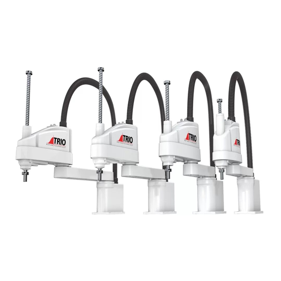
TRIO SCARA Robot Mechanical Unit Operator's Manual Preface This manual describes the following robots. Robot Type Load Capacity RX3-400-SR RX6-500-SR RX6-600-SR RX6-700-SR Related manuals Trio SCARA Assembly and Wiring Manual Document Version: 1.8 © 2022 TRIO MOTION TECHNOLOGY All right reserved. -
Page 11: Table Of Contents
TRIO SCARA Robot Mechanical Unit Operator's Manual Contents Safety ....................iii Preface....................x Related manuals ...................... x Specifications ................1 1.1. Model Number ....................1 1.2. Part Names and Outer Dimensions .................2 1.3. Specifications ....................6 Environment and installation ............9 2.1. Environmental Conditions ...................9 2.1.1. - Page 12 TRIO SCARA Robot Mechanical Unit Operator's Manual 5.2. Greasing ..................... 45 5.2.1. Greasing Procedures ................. 46 5.3. Tightening Hexagon Socket Head Cap Bolts ............47 5.4. Maintenance of the Belt .................. 49 5.4.1. Belt specifications ................... 50 5.4.2. Failure mode of timing belt ................ 51 Calibration and battery ..............
-
Page 13: Specifications
TRIO SCARA Robot Mechanical Unit Operator's Manual 1. Specifications 1.1. Model Number Document Version: V1.8 © 2022 TRIO MOTION TECHNOLOGY All right reserved. -
Page 14: Part Names And Outer Dimensions
TRIO SCARA Robot Mechanical Unit Operator's Manual 1.2. Part Names and Outer Dimensions Be careful of the shaft while the brake release switch is being pressed because the shaft may be lowered by the weight of the end effector. While the LED lamp is on, the current is being applied to the robot. Performing any work with the power ON is extremely hazardous and it may result in electric shock and/or improper function of the robot system. - Page 15 TRIO SCARA Robot Mechanical Unit Operator's Manual Fig 1.2 Dimension of RX3 robot Document Version: V1.8 © 2022 TRIO MOTION TECHNOLOGY All right reserved.
- Page 16 TRIO SCARA Robot Mechanical Unit Operator's Manual Fig 1.3 Part name (RX6) Document Version: V1.8 © 2022 TRIO MOTION TECHNOLOGY All right reserved.
- Page 17 TRIO SCARA Robot Mechanical Unit Operator's Manual Fig 1.4 Dimension of RX6 (STANDARD) robot Document Version: V1.8 © 2022 TRIO MOTION TECHNOLOGY All right reserved.
-
Page 18: Specifications
TRIO SCARA Robot Mechanical Unit Operator's Manual 1.3. Specifications RX3-XXX-SR RX6-XXX-SR Item Arm#1 & #2 (mm) Arm length Arm#1 (mm) Arm#2 (mm) Joint#1, #2 (mm/s) 5400 6000 6650 5900 Max. operating speed Joint#3 (mm/s) 1000 Joint#4 (°/s) 2250 1730 Joint#1, #2 (mm) ±0.025 ±0.025 Repeatability... - Page 19 TRIO SCARA Robot Mechanical Unit Operator's Manual Power consumption (kW) 0.09 0.12 0.12 0.12 (Servo ON at zero position) Power consumption (kW) 0.07 0.07 0.09 0.09 (Servo OFF at zero position) Driving method All joints AC servo motor Joint #1 (W) Joint #2 (W) Motor energy consumption...
- Page 20 TRIO SCARA Robot Mechanical Unit Operator's Manual Max. motion range Item Joint#1 (°) Joint#2 (°) Joint#3 (mm) Joint#4 (°) RX3-400-SR ±132 ±141 ±360 RX6 series ±132 ±150 ±360 Document Version: V1.8 © 2022 TRIO MOTION TECHNOLOGY All right reserved.
-
Page 21: Environment And Installation
TRIO SCARA Robot Mechanical Unit Operator's Manual 2. Environment and installation 2.1. Environmental Conditions A suitable environment is necessary for the robot system to function properly and safely. Be sure to install the robot system in an environment that meets the following conditions: Item Conditions Ambient temperature*... -
Page 22: Special Environmental Conditions
TRIO SCARA Robot Mechanical Unit Operator's Manual 2.1.1. Special Environmental Conditions The robot surface is generally oil resistant. Please consult your distributor if you are concerned about a certain type of oil in your application’s environment. Rapid change in temperature and humidity might cause condensation inside the Robot. For food handling, please consult your distributor if you feel any concern regarding the robot being suitable to handle the material. -
Page 23: Base Table
TRIO SCARA Robot Mechanical Unit Operator's Manual 2.2. Base Table A base table for anchoring the Robot is not supplied. Please make or obtain the base table for your Robot. The shape and size of the base table differs depending on the use of the robot system. For your reference, we list some Robot table requirements here. -
Page 24: Mounting Dimension
TRIO SCARA Robot Mechanical Unit Operator's Manual 2.3. Mounting Dimension The maximum space described in section 1.2 shows that the radius of the end effector is 60 mm or less. If the radius of the end effector exceeds 60 mm, define the radius as the distance to the outer edge of maximum space. - Page 25 TRIO SCARA Robot Mechanical Unit Operator's Manual Fig 2.2 Motion range (RX3-400-SR) Document Version: V1.8 © 2022 TRIO MOTION TECHNOLOGY All right reserved.
- Page 26 TRIO SCARA Robot Mechanical Unit Operator's Manual Fig 2.3 Motion range (RX6 Standard model) Document Version: V1.8 © 2022 TRIO MOTION TECHNOLOGY All right reserved.
- Page 27 TRIO SCARA Robot Mechanical Unit Operator's Manual RX3-XXX-SR RX6-XXX-SR Item Length of Arm #1& Arm #2 (mm) Length of Arm #1 (mm) Length of Arm #2 (mm) Motion range of Joint #1 (°) ±132 ±132 ±132 Motion range of Joint #2 (°) ±150 ±150 ±150...
-
Page 28: Unpacking And Transportation
TRIO SCARA Robot Mechanical Unit Operator's Manual 2.4. Unpacking and Transportation Only authorized personnel should perform sling work and operate a crane and a forklift. When these operations are performed by unauthorized personnel, it is extremely hazardous and may result in serious bodily injury and/or severe equipment damage to the robot system. - Page 29 TRIO SCARA Robot Mechanical Unit Operator's Manual After removing the bolts securing the Robot to the delivery equipment, the Robot can fall. Be careful not to get hands or fingers caught. The arm is secured with a wire tie. Leave the wire tie secured until you finish the installation so as not to get hands or fingers caught.
- Page 30 TRIO SCARA Robot Mechanical Unit Operator's Manual Parts Weight (kg) RX3-400-SR RX6-500-SR Robot RX6-600-SR RX6-700-SR Cabinet Some lightweight parts are not listed on the above table. NOTE Document Version: V1.8 © 2022 TRIO MOTION TECHNOLOGY All right reserved.
-
Page 31: Installation Procedure
TRIO SCARA Robot Mechanical Unit Operator's Manual 2.5. Installation Procedure The robot system must be installed to avoid interference with buildings, structures, utilities, other machines, and equipment that may create a trapping hazard or pinch points. Vibration (or sympathetic vibration) may occur during operation as the rigidity CAUTION of worktable. - Page 32 TRIO SCARA Robot Mechanical Unit Operator's Manual Use bolts with specifications conforming to ISO898-1 Property Class: 10.9 or 12.9. The tightening torque is 73.5 N·m (750kgf·cm). CAUTION (2) Using nippers, cut off the wire tie binding the shaft and arm retaining bracket on the base. (3) Remove the bolts securing the wire ties removed in step (2).
-
Page 33: Connecting The Cables
TRIO SCARA Robot Mechanical Unit Operator's Manual 2.6. Connecting the Cables To shut off power to the robot system, pull out the power plug from the power source. Be sure to connect the AC power cable to a power receptacle. DO NOT connect it directly to a factory power source. -
Page 34: User Wires And Pneumatic Tubes
TRIO SCARA Robot Mechanical Unit Operator's Manual 2.7. User Wires and Pneumatic Tubes Only authorized or certified personnel should be allowed to perform wiring. Wiring by unauthorized or uncertified personnel may result in bodily injury and/or CAUTION malfunction of the robot system. User electrical wires and pneumatic tubes are contained in the cable unit. -
Page 35: Electrical Wires
TRIO SCARA Robot Mechanical Unit Operator's Manual 2.7.1. Electrical Wires Rated Voltage Allowable Current Wires Nominal Sectional Area Note AC/DC 30V 0.211mm Twisted pair Do not apply the current more than 1A to the robot. WARNING Pins with the same number, indicated on the connectors on both ends of the cables, are connected. Connectors are standard accessories of the robot;... -
Page 36: Pneumatic Tubes
TRIO SCARA Robot Mechanical Unit Operator's Manual 2.7.2. Pneumatic Tubes Max. Usable Pneumatic Pressure Pneumatic tubes Outer Diameter × Inner Diameter ø6 mm × ø4 mm 0.59 MPa (6 kgf/cm :86 psi) ø4 mm × ø2.5 mm Fittings for ø6 mm and ø4 mm (outer diameter) pneumatic tubes are supplied on both ends of the pneumatic tubes. - Page 37 TRIO SCARA Robot Mechanical Unit Operator's Manual Fig 2.7 Fittings for tubes (RX3 & RX6) Document Version: V1.8 © 2022 TRIO MOTION TECHNOLOGY All right reserved.
-
Page 38: Relocation And Storage
TRIO SCARA Robot Mechanical Unit Operator's Manual 2.8. Relocation and Storage 2.8.1. Precautions for Relocation and Storage When transporting the Robot for a long distance, secure it to the delivery equipment so that the Robot cannot fall. If necessary, pack the Robot in the same way as it was delivered. If necessary, pack the Robot in the same way as it was delivered. -
Page 39: Relocation
TRIO SCARA Robot Mechanical Unit Operator's Manual 2.8.2. Relocation (1) Turn OFF the power on all devices and unplug the cables. (2) Cover the arm with a sheet so that the arm will not be damaged. Tie the lower end of the shaft and arm, and the base and arm together with the wire tie. -
Page 40: Setting Off End Effectors
TRIO SCARA Robot Mechanical Unit Operator's Manual 3. Setting Off End Effectors 3.1. Attaching an End Effector Users are responsible for making their own end effector(s). Before attaching an end effector, observe these guidelines. If you use an end effector equipped with a gripper or chuck, connect wires and/or pneumatic tubes properly so that the gripper does not release the work piece when the power to the robot system is turned OFF. -
Page 41: Shaft
TRIO SCARA Robot Mechanical Unit Operator's Manual 3.1.1. Shaft Attach an end effector to the lower end of the shaft. For the shaft dimensions, and the overall dimensions of the Robot, refer to chapter 1. Specifications. Use a split muff coupling with an M4 bolt or larger to attach the end effector to the shaft. Document Version: V1.8 ©... -
Page 42: Brake Release Switch
TRIO SCARA Robot Mechanical Unit Operator's Manual 3.1.2. Brake release switch Joint #3 cannot be moved up/down by hand because the solenoid brake is applied to the joint while power to the robot system is turned OFF. This prevents the shaft from hitting peripheral equipment in the case that the shaft is lowered by the weight of the end effector when the power is disconnected during operation, or when the motor is turned OFF even though the power is turned ON. -
Page 43: Layouts
TRIO SCARA Robot Mechanical Unit Operator's Manual 3.1.3. Layouts When you operate the robot with an end effector, the end effector may interfere with the Robot because of the outer diameter of the end effector, the size of the work piece, or the position of the arms. -
Page 44: Attaching Cameras And Valves
TRIO SCARA Robot Mechanical Unit Operator's Manual 3.2. Attaching Cameras and Valves The bottom of the Arm #2 has threaded holes as shown in the figure below. Use these holes for attaching cameras, valves, and other equipment. Fig 3.1 Dimensions for attaching cameras and valves (RX3) Document Version: V1.8 ©... - Page 45 TRIO SCARA Robot Mechanical Unit Operator's Manual Fig 3.2 Dimensions for attaching cameras and valves (RX6) Document Version: V1.8 © 2022 TRIO MOTION TECHNOLOGY All right reserved.
-
Page 46: Equivalent Weight
TRIO SCARA Robot Mechanical Unit Operator's Manual 3.2.1. Equivalent weight When you attach a camera or valve to the arm, calculate the weight as the equivalent of the shaft. Then add this to the load. Equivalent weight formula is shown below. When you attach the equipment near Arm #2: ��... - Page 47 TRIO SCARA Robot Mechanical Unit Operator's Manual Fig 3.3 Equivalent weight calculation Document Version: V1.8 © 2022 TRIO MOTION TECHNOLOGY All right reserved.
-
Page 48: Motion Range
TRIO SCARA Robot Mechanical Unit Operator's Manual 4. Motion Range 4.1. Motion Range Setting by Mechanical Stops Mechanical stops physically limit the absolute area that the Robot can move. Fig 4.1 Mechanical stops (RX3) Fig 4.2 Mechanical stops (RX6) Document Version: V1.8 ©... - Page 49 TRIO SCARA Robot Mechanical Unit Operator's Manual Do not move the upper limit mechanical stop. Moving the upper limit mechanical stop may lead to collision with robot and may result in malfunction of the robot system. Document Version: V1.8 © 2022 TRIO MOTION TECHNOLOGY All right reserved.
-
Page 50: Setting The Mechanical Stops Of Joints #1 And #2
TRIO SCARA Robot Mechanical Unit Operator's Manual 4.1.1. Setting the Mechanical Stops of Joints #1 and #2 Both Joints #1 and #2 have threaded holes in the positions corresponding to the angle for the mechanical stop settings. Install the bolts in the holes corresponding to the angle that you want to set. The angle for Joint #3 can be set in any value within the maximum range. - Page 51 TRIO SCARA Robot Mechanical Unit Operator's Manual Fig 4.4 Mechanical stops (RX6) Type Angle for the J1 axis mechanical stop Angle for the J2 axis mechanical stop ±110° ±125° ±115° ±125° Document Version: V1.8 © 2022 TRIO MOTION TECHNOLOGY All right reserved.
-
Page 52: Maintenance
TRIO SCARA Robot Mechanical Unit Operator's Manual 5. Maintenance This chapter describes maintenance inspections and procedures. Performing maintenance inspections and procedures properly is essential for preventing trouble and ensuring safety. Be sure to perform the maintenance inspections in accordance with the schedule. Never perform any maintenance unless shut down the system. -
Page 53: Schedule For Maintenance Inspection
TRIO SCARA Robot Mechanical Unit Operator's Manual 5.1. Schedule for Maintenance Inspection Inspection points are divided into five stages: daily, monthly, quarterly, biannual, and annual. The inspection points are added every stage. If the Robot is operated for 250 hours or longer per month, the inspection points must be added every 250 hours, 750 hours, 1500 hours, and 3000 hours operation. - Page 54 TRIO SCARA Robot Mechanical Unit Operator's Manual Inspection Point (h=hour) Daily Monthly Quarterly Biannual Annual Maintenance inspection inspection inspection inspection inspection 1 month(250h) ✓ 2 months(500h) ✓ 3 months(750h) ✓ ✓ 4 months(1000h) ✓ 5 months(1250h) ✓ 6 months(1500h) ✓ ✓...
-
Page 55: Inspection While Power Is Off (Robot Is Not Operating)
TRIO SCARA Robot Mechanical Unit Operator's Manual 5.1.1. Inspection While Power is OFF (Robot is not operating) Inspection Point Inspection Place Daily Monthly Quarterly Biannual Annual End effector mounting bolts ✓ ✓ ✓ ✓ ✓ Robot mounting bolts ✓ ✓ ✓... -
Page 56: Inspection While The Power Is On (Robot Is Operating)
TRIO SCARA Robot Mechanical Unit Operator's Manual 5.1.2. Inspection While the Power is ON (Robot is operating) Inspection Point Inspection Place Daily Monthly Quarterly Biannual Annual Check motion range Each joint ✓ Move the cables back and forth lightly External cables to check whether the cables are (including cable ✓... -
Page 57: Greasing
TRIO SCARA Robot Mechanical Unit Operator's Manual 5.2. Greasing The ball screw spline and reduction gear units need greasing regularly. Only use the grease specified in the following table. Keep enough grease in the Robot. Operating the Robot with insufficient grease will damage sliding parts and/or result in insufficient function of the Robot. -
Page 58: Greasing Procedures
TRIO SCARA Robot Mechanical Unit Operator's Manual 5.2.1. Greasing Procedures Please cover the furniture and peripheral equipment, etc., in case that grease/oil falls. (1) Turn the controller power ON. (2) Move the arm to the position that Joint #3 is to its full motion distance. (3) Press the brake release switch. -
Page 59: Tightening Hexagon Socket Head Cap Bolts
TRIO SCARA Robot Mechanical Unit Operator's Manual 5.3. Tightening Hexagon Socket Head Cap Bolts Hexagon socket head cap bolts are used in places where mechanical strength is required. (A hexagon socket head cap bolt will be called a “bolt” in this manual.) These bolts are fastened with the tightening torques shown in the following table. - Page 60 TRIO SCARA Robot Mechanical Unit Operator's Manual The bolts aligned on a circumference should be fastened in a crisscross pattern as shown in the figure below. Do not fasten all bolts securely at one time. Divide the number of times that the bolts are fastened into two or three and fasten the bolts securely with a hexagonal wrench.
-
Page 61: Maintenance Of The Belt
TRIO SCARA Robot Mechanical Unit Operator's Manual 5.4. Maintenance of the Belt Item Model Notes Tool Acoustic tension gates U507 For details about measurement, refer to specification of meter the acoustic tension meter. Document Version: V1.8 © 2022 TRIO MOTION TECHNOLOGY All right reserved. -
Page 62: Belt Specifications
TRIO SCARA Robot Mechanical Unit Operator's Manual 5.4.1. Belt specifications Model Belt Mess (g/mm*m) Width (mm) Span (mm) Internal stress (N) Tense (kgf) Belt of Joint #3 34.3 7±0.5 Short belt of Joint #4 6±0.5 series Long belt of Joint #4 10±0.5 Belt of Joint #3 34.4... -
Page 63: Failure Mode Of Timing Belt
TRIO SCARA Robot Mechanical Unit Operator's Manual 5.4.2. Failure mode of timing belt Periodical maintenance of the timing belt should be performed. Abnormal item Appearance Abnormal wear on The tooth cloth fiber fluffs, the rubber peels down, the gear tooth the color tends to white, the vein of the cloth tends to (initial) indistinct. -
Page 64: Calibration And Battery
TRIO SCARA Robot Mechanical Unit Operator's Manual 6. Calibration and battery 6.1. Introduction Calibration associates the angle of each robot axis with the pulse count value supplied from the absolute Pulse coder connected to the corresponding axis motor. To be specific, calibration is an operation for obtaining the pulse count value, corresponding to the home position. -
Page 65: Finding Calibration Position
TRIO SCARA Robot Mechanical Unit Operator's Manual 6.2. Finding calibration position Calibrating is performed at the factory with no loads on the robot system, based on the robot parameters and the special tools and software. This calibration method is the most precise one. Every robot is provided with its calibration values. -
Page 66: Battery Replacement Steps
TRIO SCARA Robot Mechanical Unit Operator's Manual 6.2.1. Battery Replacement Steps Turn power off for all axis drives. Move J1, J2, J3 and J4 and align the mark on the different arms to the position as shown in the figures below. Fig 6.1 Home position of Joint #1 (RX3&RX6) Fig 6.2 Home position of Joint #2 (RX3 &... - Page 67 TRIO SCARA Robot Mechanical Unit Operator's Manual 92mm 48.5mm 30mm Fig 6.4 Home position of Joint #3 and #4 (RX6) Remove the backplate of the battery compartment in the robot base Replace batteries of J1, J2, J3 and J4 or unplug and then plug them again so absolute encoders multi turn is set to 0.
-
Page 68: Calibration Values Reset
TRIO SCARA Robot Mechanical Unit Operator's Manual 6.2.2. Calibration Values Reset Start Motion Perfect and create a new project in Motion Perfect Make sure the Ethercat network is in operational state and all axes are all in working state (no errors). - Page 69 TRIO SCARA Robot Mechanical Unit Operator's Manual Go to individual axis by clicking the axis icon in Intelligent Drives window and clear any errors of each axis by ‘Clear All Errors’, ‘Clear Multi-turns Errors’, and ‘Clear Active’ in sequence as shown below. Fig 6.7 Motion Perfect Intelligent Drives window Make sure the controller status is without errors as shown below Fig 6.8 Controller status in Motion Perfect...
- Page 70 TRIO SCARA Robot Mechanical Unit Operator's Manual Fig 6.9 Encoder values in Axis Parameters window Restart the cabinet Via Motion Perfect, make sure the Ethercat network is operational. If not, restart Ethercat network via Controller pane in Motion Perfect. Fig 6.10 Restart EtherCAT network Axis parameter ENCODER (previously of about 0) for each axis should now reflect the proximity of the value in Calibration Data document.
-
Page 71: Scara Definition
TRIO SCARA Robot Mechanical Unit Operator's Manual 6.2.3. SCARA Definition Run ROBOT_DEFINITIONS file. Switch Master Enable ON and test jog each axis of the robot. Fig 6.12 Motion Perfect Robot Jog window Document Version: V1.8 © 2022 TRIO MOTION TECHNOLOGY All right reserved. -
Page 72: Appendix
TRIO SCARA Robot Mechanical Unit Operator's Manual Appendix Appendix A RX3 Maintenance Parts List Note: illustration may show different model. RX3 Robot Parts Name Part name Code Note Maintenance Joint #1 12700000053 ● AC Servo Joint #2 12700000049 ● Motor Joint #3/#4 12700000048 Joint #3... - Page 73 TRIO SCARA Robot Mechanical Unit Operator's Manual Battery 51205A00001 Ball Screw Spline A2144000012 AFB-LF+400 Grease Contact franchiser or TRIO Reduction Gear Unit for purchasing grease. RX3 Robot Parts List Document Version: V1.8 © 2022 TRIO MOTION TECHNOLOGY All right reserved.
-
Page 74: Appendix B Rx6 Maintenance Parts List
TRIO SCARA Robot Mechanical Unit Operator's Manual Appendix B RX6 Maintenance Parts List Note: illustration may show different model. RX6 Robot Parts Name Part name Code Note Maintenance Joint #1 12700000057 ● AC Servo Joint #2 12700000053 ● Motor Joint #3/#4 12700000048 ●... - Page 75 TRIO SCARA Robot Mechanical Unit Operator's Manual Ball Screw Spline A2144000012 AFB-LF+400 Grease Contact franchiser or TRIO for Reduction Gear Unit purchasing grease. RX6 Robot Parts List Document Version: V1.8 © 2022 TRIO MOTION TECHNOLOGY All right reserved.
-
Page 76: Revision History
TRIO SCARA Robot Mechanical Unit Operator's Manual Revision History Date Version Revised Contents Jan 2021 V1.0 First Draft (BD) May 2021 V1.1 ER3 & ER6 checks – RX3 & RX6 (RT) Jun 2021 V1.2 More information on Calibration and Battery section (chap. 6) (RT) Jul 2021 V1.3 Danger, Warning and Caution box colour indicators (RT) - Page 77 TRIO SCARA Robot Mechanical Unit Operator's Manual Trio Motion Technology Limited www.triomotion.uk Document Version: V1.8 © 2022 TRIO MOTION TECHNOLOGY All right reserved.
Need help?
Do you have a question about the TRIO SCARA RX3 and is the answer not in the manual?
Questions and answers