Table of Contents
Advertisement
Quick Links
Advertisement
Table of Contents

Related Manuals for Estun C2E Series


Summary of Contents for Estun C2E Series
- Page 1 ESTUN Robotics C2E Series Operation Instructions of Control Cabinet...
- Page 2 ESTUN Robotics C2E Series Control Cabinet Operation Manual E-0802EN-05...
- Page 3 Thank you for purchasing ESTUN robots. Before using the robot, be sure to read the SAFETY PRECAUTION and understand the content. ESTUN is committed to prove the products. All specifications and designs are subject to change without notice. All statements, information, and advice provided in this manual have been carefully processed, but no guarantee is given for their complete accuracy.
- Page 4 Revision History Revision Date Content 2022.09 Initial release. Updated Figure 3-2 Single-Phase Power Distribution (ED3L-A) diagram in 2022.12 Section 3.4.2. 1.Updated the electrical diagram, basic parameter table information, and modified the error description. 2023.12 2. ESView software and teach pendant pictures. 3.
- Page 5 This Chapter describes the content to be observed for the safe use of the robot. Before using, be sure to read and understand the content in this Chapter. Companies and individuals using Estun Robotics should be familiar with the local and national standards and laws. Appropriate safety facilities shall be provided to protect users. Before use...
- Page 6 2, Installation precautions: (1) Follow the specified methods for handling and installing the robot. When handling and installing the robot, follow the methods specified by Estun Robotics. Using incorrect methods may result in the robot tipping over and causing accidents;...
- Page 7 Safety Precautions (5) Ensure proper grounding for all peripheral devices; (6) Draw an area clearly indicates the safety area. Install a fence or hang a warning board to ensure the safety operation of the robot, and keep unauthorized personnel outside the safety area; (7) Exercise caution when disassembling the robot to avoid injury from falling components;...
- Page 8 Operations such as handling, setup, teaching, adjustment, and maintenance must be conducted within a safety area by personnel who have received professional training in robotics. For more information regarding training, please contact ESTUN Robotics Engineering Co., Ltd. Precautions for users...
- Page 9 Safety Precautions Programmers While teaching the robot, and in some cases, the programmer needs to enter the range of the robot's movement, so be sure to keep himself safe. ON/OFF enabling is done by operating a Mot button on the teach pendant. When pressing this button, the servomotor is enabled, and disabled when releasing it.
- Page 10 Safety Precautions equipment. Therefore, it is necessary to release the residual energy in the system before maintaining the pneumatic or hydraulic components. Mount a safety valve to avoid accidents. (4) The power supply need be opened in many cases of fault diagnosis, but it must be shut when the maintenance or repair is carried, moreover, you should cut off other power supply connections.
- Page 11 Safety Precautions Power-Off Stop Servo power is turned off and the robot stops immediately. Servo power is turned off when the robot is moving, and the motion path of the deceleration is uncontrolled. The following processing is performed at Power-Off stop: ⚫...
- Page 12 Safety Precautions Symbol Description Wounding by robot There is a danger of wounding by robot when working within the motion range of robot. No disassembly Users are prohibited from disassembling the part affixed with this sign. Disassembly shall be carried out by professionals using professional tools.
-
Page 13: Safety Precautions
Preface Preface This document describes how to use the C2E control cabinet. The C2E is a compact horizontal control cabinet. This manual is intended for the following robot models. Control cabinet Specific control cabinet models Type series ER7-910-MI ERC-C2-E4SA (ED3L-A) ER8-720-MI ER10B-900-MI/HI ERC-C2-E4SC (ED3L-B) -
Page 14: Table Of Contents
CONTENTS CONTENTS Revision History ........................ 4 Safety Precautions......................1 Definition of users ..........................1 Safety Symbols ..........................1 Safety Precautions ........................... 2 Safety Precautions......................1 Precautions for users ........................1 Safety precautions for robot ......................3 Ways to stop robot ..........................3 Safety precautions for tools and peripheral equipment .............. -
Page 15: Safety Precautions For Robot
CONTENTS 4.2.1 Connection of teach pendant ..................... 32 4.2.2 Editing method ........................32 4.3 Use of ESView software ......................34 4.3.1 Connecting the servo drive unit ..................34 4.3.2 Installing ESView ....................... 35 4.3.3 Enabling ESView ........................ 43 4.3.4 Parameter settings ......................47 4.4 Definition of parameters ...................... -
Page 16: Revision History
Product Information Chapter 1 Product Information Product Information The C2E series control cabinets include three models: ERC-C2-E4SA (ED3L-A) and ERC-C2-E4SC (ED3L-B) ERC-C2-E4SA (ED3L-A) is referred to as "C2-ED3L-A" or "ED3L-A" in this manual ERC-C2-E4SC (ED3L-B) is referred to as "E4SC (ED3L-B)" in this manual 1.1 Information on nameplate... -
Page 17: Overall Dimensions
Product Information 1.3 Components Description of appearance Main power switch E-stop button Fig 1-3 Description of appearance Internal structure Inside the control cabinet, multi-core cables should be used for wiring. Avoid leaving excessively long wiring and check for any cable entanglement. -
Page 18: Preface
Product Information Resistance box Heat exchanger Grounding copper Driver Relay module board Controller Switching power supply IO module AC contactor O&M Wizard (optional) Filter Fig 1-4 Internal structure (ED3L-A) Heat exchanger Resistive Copper coin of the chamber current convergence Driver Controller Filter Relay... -
Page 19: Contents
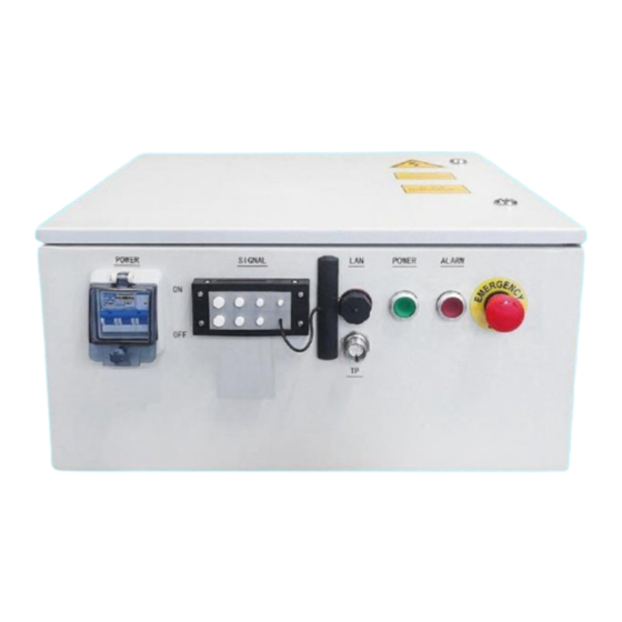
Product Information External interface Through-wall LAN interface plate Power LED Fault LED Protective cover (power control switch included) E-stop switch Teach pendant cable interface Fig 1-6 External interface 1.4 Basic parameters Table Basic parameters list of control cabinet Reference Dimensions Self- Rated energy... - Page 20 Product Information Non-flexible cables: ≥690mmm Power cable bending radius Flexible cables: ≥200mmm Non-flexible cables: ≥400mmm Encoder cable bending radius Flexible cables: ≥200mmm Non-flexible cables: ≥260mmm IO cable bending radius Flexible cables: ≥130mmm Noise level 50-75dB Table Control cabinet specifications Item Spec.
- Page 21 Product Information Fig. 1-7 Product Dimensions of ERC-C2-E4SA(ED3L-A), ERC-C2-E4SC(ED3L-B)
-
Page 22: Chapter 2 Transportation & Installation
Transportation & Installation Chapter 2 Transportation & Installation 2.1 Transportation Handle horizontal control cabinets on pallets during transportation. During transportation, avoid vibration, dropping, or impacting the control cabinet. Excessive vibration or impact can have harmful effects on its performance. Moisture protection measures should also be taken. -
Page 23: Installation Location
Transportation & Installation Fig.2-1 Installation Diagram 2.2.3 Installation location ⚫ The control cabinet should be installed outside the range of robot movement (within a safety fence) Security fence Electrical control Door cabinet Range of motion of the robot arm Maximum range of motion of the robot arm, including the end of the tool ⚫... -
Page 24: Chapter 3 Wiring & Connection
Wiring & Connection Chapter 3 Wiring & Connection ⚫ The system must be electrically grounded to avoid fire, electric shock and bodily injury. ⚫ Turn off the main power switch prior to wiring and inspection to avoid electric shock and bodily injury. ⚫... -
Page 25: Residual-Current Circuit Breaker
Wiring & Connection Piping Wiring duct Wiring ⚫ The wiring and routing of encoder cables must be separated from power cables. If they are placed in the same cable conduit, isolators must be used to keep them separated. 3.2 Residual-current circuit breaker The power supply of the robot control device may have high-frequency leakage currents, which can sometimes cause the unintended operation of the residual current devices or residual current protection relays installed on the upper-level robot control device. -
Page 26: Power Supply Wiring
Wiring & Connection Name Description Mains power cable IO cable interface Undefined input and output signal interfaces RJ45 interface Communication interface to the vision module Encoder cable Motor encoder cable interface for each axis of the robot to collect the robot position signal and connect to the robot body using a special cable. -
Page 27: Electrical Principle
Wiring & Connection 3.4.2 Electrical principle Power distribution Fig. 3-2 Single-phase power distribution (ED3L-A and E4SC (ED3L-B)) 360V drive control power supply Fig. 3-3 Three-phase power distribution (ED3L-B) - Page 28 Wiring & Connection Control power supply 24V Control Power Positive Control power negative Fig. 3-4 Control power supply 24V Cooling fan EV1~EV2 DC fans Fig. 3-5 Cooling fan...
- Page 29 Wiring & Connection DC 24V control loop If an external serial-in E-stop is required, remove the brake wire from the terminal Fig. 3-6 DC 24V control loop AC 220V control loop Fig. 3-7 AC220V control loop...
-
Page 30: Teach Pendant
Wiring & Connection Motor brake Fig. 3-8 Motor brake 3.5 Teach pendant 3.5.1 Precautions for using teach pendant Handle with care and avoid dropping, throwing, or striking the teach pendant, as this may cause damage or malfunction. When not in use, hang it on the dedicated holder to prevent accidental dropping (our internal drop test result is satisfactory at a height of 1 meter);... -
Page 31: Apperance Of Teach Pendant
Wiring & Connection 3.5.2 Apperance of teach pendant Fig. 3-1 Exterior of the Teach Pendant Description Display E-stop button Mode selector switch Global function buttons 4a, 4b, 4c Status LED Servo enable switch Suspension handle Cable access area USB slot Stylus pen Name Description... -
Page 32: Teach Pendant Interface Definition
Wiring & Connection Name Description Accessories Emergency stop; key switch; enable switch (3 digits) Display color quality -bit color Power consumption 24V 1A Compatible power supply DC24V 1A and above models Housing material, color ABS/PC; BLACK/GRAY Operating environment Operating temperature : 0°... -
Page 33: Electrical Principle
Wiring & Connection Teach pendant 3.5.5 Electrical principle ESTUN teach pendant Power supply E-stop Enable Connect to ETHERNETO via RJ45 Fig. 3-9 Teach Pendant Wiring... -
Page 34: Io Wiring
Wiring & Connection 3.6 IO wiring 3.6.1 IO Interface definition Definition Definition 3.6.2 Signal specifications The technical specifications of the digital input/output expansion module EC4-1616A are shown in the table below Table 3-2 Table of technical parameters EC4-1616A Interface parameters Bus protocol EtherCAT Number of I/O stations... - Page 35 Wiring & Connection Data transmission medium Ethernet/EtherCAT CAT5 cable ≤100 m (station-to-station distance) Transmission distance Transmission rate 100 Mbps Bus interface 2xRJ45 Technical parameters Configuration mode Via Master Power supply 18 to 36 VDC Electrically isolated 500 V Weight Approx. 140 g Dimensions 102 mmx72 mmx25 mm Operating temperature...
- Page 36 Wiring & Connection Load Max. output current 250mA Fig. 3-10 DO NPN type wiring diagram Fig. 3-11 DI PNP type wiring diagram Load Max. output current 250mA Fig. 3-12 DO PNP type wiring diagram Fig. 3-13 DI NPN type wiring diagram...
-
Page 37: Encoder Interface Definition
Wiring & Connection 3.6.3 Encoder Interface Definition Table 3-1 Encoder Definition Description Definition Description 1S+ Housing 1S﹣ Wiring of the J1 motor Wiring of the J4 motor 5V-1 encoder encoder 0V-1 5V-4 Housing 0V-4 Housing 2S+ 2S﹣ 5S﹣ Wiring of the J2 motor Wiring of the J5 motor encoder encoder... -
Page 38: Controller
Wiring & Connection 3.7 Controller The controller is the motion control device of the robot system, which receives instructions from the teach pendant and sends control signals. It is the core component of the system. Power Status interface display interface interface interface Item... - Page 39 Wiring & Connection Communication connections Expansion network port Teach pendant connector Fig. 3-14 Communication Connection Diagram (Optional O&M Wizard) Expansion network port Teach pendant connector Fig. 3-15 Communication Connection Diagram (without O&M Wizard)
- Page 40 Wiring & Connection E-stop wiring Fig. 3-16 E-stop wiring diagram Wiring terminals E002 and E006 may connect to external emergency stop signals, and wiring terminals E004 and E008 may connect to external emergency stop signals. When there is an external emergency stop or safety door signal, the splice should be removed. Coupler power supply Coupler Coupler...
- Page 41 Wiring & Connection Controller power supply/DC24V Robot autonomous controller Fig. 3-18 Controller Power Supply Input module EC4-1616A D1 Part Reload program Reserved Module power supply Fig. 3-19 Input module...
-
Page 42: Relay Module
Wiring & Connection Output module EC4-1616A D0 Part Fig. 3-20 Output module 3.8 Relay module The model of the relay module is 11261100001 (relay module ER-Relay-A). Its integrated 18 LED indicators indicate the current status in detail, which has a guiding effect on the maintenance of the internal lines of the control cabinet. - Page 43 Wiring & Connection Description LED ON LED OFF Servo mains indicator E-stop LED No E-stop With E-stop Servo alarm LED No alarm With alarm Teach pendant Not provided Provided Servo power LED Axis alarm status LED, corresponding to the alarm status of each of the 6 axes.
-
Page 44: Chapter 4 Debugging
Debugging Chapter 4 Debugging 4.1 Checks before power-on Before powering on the control cabinet, please check and confirm the following items, and make necessary adjustments if needed. Content Inspect the appearance of the control cabinet both inside and outside. Check if the fastening screws are securely connected. Verify the status of connectors and installation locations of each unit in the control cabinet. - Page 45 Debugging Step 2: After initialization is completed, check the system's operating status using the status indicator LEDs on the teach pendant. The Run indicator LED should be continuously on, and the Err indicator LED should be off, indicating a normal operating state. Step 3: When the teach pendant displays the Home screen, select "General Settings >...
-
Page 46: Use Of Esview Software
Debugging Step 5: In the parameter dialog box that appears, set the desired parameters. Please note that the teach pendant can only be used to set certain Pn parameters. If you wish to set more parameters, please use the operating panel. 4.3 Use of ESView software 4.3.1 Connecting the servo drive unit To perform online operations, connect the PC and the servo drive unit using a USB-RS485 (RJ45) -
Page 47: Installing Esview
Debugging Step 5: Refer to the connection diagram in the provided figure below, and use a USB-RS485 (RJ45) communication cable to connect the PC and the servo drive unit. Plug the Mini USB into the drive's CNS Plug USB into PC Lift the interlock latch at the lower right corner, then rotate the switch from "OFF"... - Page 48 Please make the following preparations before installation: Windows operating system, communication cable, and decompression software. Log in to the official website of ESTUN at www.estun.com and navigate to the "Downloads" section to find and download the ESView V4 software. If you are unable to obtain the software or require assistance, please contact ESTUN engineers.
- Page 49 Click "Device Manager" in "All Control Panel Items" to bring up the "Device Manager" window. For Windows 10, right-click on "Start", then select "Device Manager" from the menu. As shown in the figure, "Other Devices" → "ESTUN USB COMM" in "Device Manager" Step 4 indicates the device with driver issue.
- Page 50 Debugging Fig. 4-2 Unrecognized device "ESTUN USB COMM" under "Device Manager" Step 5 Right-click on "ESTUN USB COMM" and choose "Update Driver Software" from the menu, as shown in the figure. Fig. 4-3 Update Driver Software Step 6 In the "Update Driver Software" dialog, select "Browse my computer for driver software" ,...
- Page 51 Debugging Fig. 4-4 Browse your computer for driver software Step 7 Select "Choose from your computer's list of device drivers" as shown in the figure. Fig. 4-5 Select from the computer's list of device driver programs Step 8 Select "Next" as shown in the figure. Fig.
- Page 52 Debugging Fig. 4-7 Install from Disk Step 10 Click "Browse" in the "Install from Disk" dialogue box that pops up, as shown in the figure. Fig. 4-8 Browse files Step 11 In the "Find File" dialog box, set the "Find Range" to the directory "\USB Drivers\windows_drivers"...
- Page 53 Debugging Fig. 4-9 Find and Open the Driver File Step 13 Return to the "Install From Disk" dialog box and click "OK". Step 14 Select "Generic Bulk Device" and click "Next", as shown in the figure. Fig. 4-10 Select the Driver to Install Step 15 In the "Update Driver Warning"...
- Page 54 Debugging Fig. 4-11 Confirm Driver Installation Step 16 After a moment, select "Install" in the "Windows Security" dialog box, as shown in the figure. Fig. 4-12 Confirm Device Installation Step 17 The driver will automatically install on the PC, and upon completion, it will display the installation result.
-
Page 55: Enabling Esview
Debugging 4.3.3 Enabling ESView Online operation Through online operation, parameters of the servo drive can be uploaded, downloaded, and more. It is recommended to perform an online operation the first time you configure a drive. Users need a USB connection cable to connect the PC to the drive before performing online operations. Step 1: Connect the drive unit to the PC using a USB connection cable. - Page 56 Debugging Fig. 4-16 Select the Device to Connect If the "Search" does not find any device, please check the connection between the device and the PC and ensure that the ESView V4 software is the latest version. Step 7: Click "Connect". Fig.
- Page 57 Debugging Fig. 4-18 Connected Device Status Now, the user can perform necessary real-time settings on the driver or motor online. Connected online devices or created offline devices will be displayed in the "Device" column. To delete a device, click at its top right corner and click "OK"...
- Page 58 Debugging Fig. 4-19 Select Offline Step 4: Choose the "Device Type" you want to configure, such as "ED3L". Fig. 4-20 Select Device Type Step 5: After entering the main window of ESView V4, the created offline device will be displayed in the "Device"...
-
Page 59: Parameter Settings
Debugging Certain functionalities are limited and cannot be configured correctly in offline operation. Connected online devices or created offline devices will be displayed in the "Device" column. To delete a device, click at its top right corner and click "OK"... - Page 60 Debugging Upload all parameters − In the "Parameter Edit" window, click on "Upload All." After a moment, ESView V4 will read and display the settings of all parameters from the drive unit in the "Device Value" column. Users can also right-click on any non-editable area of the parameter list and select −...
- Page 61 Debugging Edit Parameters After successfully uploading parameters, users can directly modify the desired parameters in the "Device Value" column, and the parameters will be updated accordingly. Fig. 4-24 Display after editing parameters When editing parameters, detailed explanations for each parameter will be displayed below the parameter list, providing assistance for user configuration.
- Page 62 Debugging Step 2: Then, in the "Save As" dialog box that pops up, choose the path where you want to store the parameter file. Step 3: Click "Save". ----END Import Parameters By performing the "Parameter Import" operation, users can download the parameter settings from an offline parameter file to the connected device.
- Page 63 Debugging − In the "Parameter Edit" window, click "Download All". After a moment, the edited parameters will be written to the driver. − Users can also right-click on any non-editable area of the parameter list, and then select "Download All" from the pop-up menu. ...
- Page 64 Debugging Restore Factory Values Performing "Restore Factory Values" will reset the parameters in the drive unit (excluding certain specified parameters) to their default settings. Please proceed with caution. Step 1: In the "Parameter Edit" window, click on "Restore Factory Values." Fig.
-
Page 65: Definition Of Parameters
Debugging 4.4 Definition of parameters Instructions for use When indicating a parameter change, the effective time of the change is as follows: "Restart": The change takes effect only after the power is restored. "Immediately": The change takes effect immediately after the parameter settings are confirmed. Factory When to take Name... - Page 66 Debugging Detailed explanation of parameters Factory When to take Name Scope Unit value effect - Basic function settings 0 0000~0111 0110 Restart Pn000.0: Servo ON 0 External S-ON is valid External S-ON is not valid. Motor excitation signal Pn000 automatically turned on after /S-RDY output Pn000.1: Reserved Pn000.2: Reserved Pn000.3: Reserved...
- Page 67 Debugging Factory When to take Name Scope Unit value effect - 1000~1301 Application function settings 5 1000 Restart Pn005.0: Torque feed-forward method General torque feedforward High-speed torque feedforward Pn005 Pn005.1: Reserved Pn005.2: Deviation alarm enable 0 Disable deviation alarm Enable deviation alarm, triggers an alarm when the deviation counter value exceeds the setting of Pn504 2 Reserved 3 Reserved...
- Page 68 Debugging Factory When to take Name Scope Unit value effect - Application function settings 6 0000~0104 0004 Restart Pn006.0: Bus type Not using bus control, but the internal speed parameter control 3 Reserved Pn006 4 Using EtherCAT bus Pn006.1: Reserved Pn006.2: Low-frequency vibration suppression switch enabling low-frequency...
- Page 69 Debugging Factory When to take Name Scope Unit value effect - Application function settings 8 0000~0001 0001 Restart Pn008.0: Alarm/warning selection 0 Alarm 1 Warning Pn008 Pn008.1: Axis shielding 0 Axis enable Axis shielding Pn008.2: Reserved Pn008.3: Reserved...
- Page 70 Debugging Factory When to take Name Scope Unit value effect - Application function settings 100 0000~0036 0000 Restart Pn100.0: Load Inertia Setting Selection 0 Manually set the percentage of load inertia (Pn106) Use conventional inertia online identification when the load inertia remains unchanged Use conventional inertia online identification when the load inertia changes slightly Use conventional inertia online identification when the...
- Page 71 Debugging Factory When to take Name Scope Unit value effect Speed loop gain 1~4000 Immediately Pn102 This value determines the magnitude of the speed loop gain. Speed loop integral time 1~4096 0.25ms Immediately Pn103 Decreasing this value will shorten the positioning time and improve the speed response. Position loop gain 0~1000 Immediately...
- Page 72 Debugging Factory When to take Name Scope Unit value effect - Output signal distribution 0000~0004 0002 Restart Pn511.0: Assign signals for CN13-20, 21/CN13-45, 46/CN13- 3, 4/CN13-28, 29/CN13-12, 13/CN13-37, 38 0 COIN/VCMP 1 TGON 2 S-RDY Pn511 3 CLT 4 WARN Pn511.1: Reserved Pn511.2: Reserved Pn511.3: Reserved...
-
Page 73: Chpter 5 Troubleshooting
Troubleshooting Chpter 5 Troubleshooting 5.1 Alarm check During the operation of the robot, alarms that occur can be viewed using the teach pendant or ESView. Once an alarm occurs, the robot will stop its motion and the user will need to take necessary actions to resolve the issue before resuming robot operation. -
Page 74: Log
Troubleshooting Step 4: Click on "Historical Alarms" at the top to access the "Historical Alarms" tab. Click the "Retrieve Historical Alarms" button to get historical alarm information. 5.2 Log Step 1: On the "Log Management" page, click the "Logs" button below to switch to the "Log" tab. Step 2: Users can view controller or teach pendant logs based on actual needs. -
Page 75: Alarm List
Troubleshooting Step 2: Click on the "Search Box", enter the "Alarm Number" or "Keyword", and click "OK" and then "Search" to find detailed information about related alarms, as shown in the figure below. 5.4 Alarm list Name Cause of fault Solution The parameters stored in the Restore factory settings (Fn001) and... - Page 76 Troubleshooting Name Cause of fault Solution Wiring errors in the analog input channels can lead to damage of the Ensure correct wiring for analog drive unit's analog input channels input interface (currently applicable only to general- purpose drives) conversion Excessive analog input voltage A.02 channel (beyond the allowable differential...
- Page 77 Troubleshooting Name Cause of fault Solution Position Incorrect drive unit parameter settings deviation in position control mode, such as Set the correct thrust limit parameter A.05 counter excessively low thrust limit value value for the drive unit overflow leading to motor stalling Drive unit parameter setting error, Position ...
- Page 78 Troubleshooting Name Cause of fault Solution Insufficient discharge capacity of the drive unit leads to increased pump Replace the small resistor with a energy, elevated bus voltage, and high-power discharge resistor potential alarms A13, A15, and A16 A.13 Overvoltage Check if the main circuit power Power supply voltage issues supply voltage is within the allowable range...
- Page 79 Check the ambient temperature and A.18 overheating the set threshold reduce the load alarm Temperature Temperature sensor not connected or Please contact ESTUN or an sensor on the damaged authorized distributor A.1D drive board disconnected Open phase in One phase of the main circuit power Ensure correct wiring of the main A.20...
- Page 80 Troubleshooting Name Cause of fault Solution If it is running unidirectionally for a Overflow of multi-turn information long time, try setting PN0071=1 Absolute A.46 for shielding encoder multi- Perform clearing operations using turn overflow Fn010 and Fn011 Low battery Encoder battery voltage below 25V ...
- Page 81 Troubleshooting Name Cause of fault Solution Try winding a magnetic ring External interference around the encoder cable and motor power lines (at least three turns) Try connecting a wire from the shield layer of the encoder cable to the motor body Serial encoder A.52 ...
- Page 82 Troubleshooting Name Cause of fault Solution Faulty drive unit Replace the drive unit Damaged motor Replace the motor Try winding a magnetic ring External interference around the encoder cable and motor power lines (at least three turns) Try connecting a wire from the shield layer of the encoder cable to the motor body Serial encoder...
- Page 83 Troubleshooting Name Cause of fault Solution EtherCAT master station configured Ensure the main station is set with with incorrect cycle settings the correct communication cycle EtherCAT Ensure SYNC0 is synchronized A.70 synchronization SYNC0 not synchronized with the with the drive unit signal error drive unit ...
-
Page 84: Chapter 6 Maintenance
Maintenance Chapter 6 Maintenance 6.1 Maintenance precautions Before performing maintenance, please carefully read the following content and ensure a thorough understanding of the methods for safe maintenance. ⚫ Maintenance of the robot system must be carried out by personnel who have received safety training. -
Page 85: Regular Inspection
Maintenance To ensure the proper functioning of the product and prevent damage, daily confirmation should be made for the following items: Item Content Solution ⚫ Check the control cabinet Verify if the installation brackets are vibrating. Installation ⚫ and surrounding cables Check for loose or corroded connections at cable environment for abnormalities... -
Page 86: Items To Confirm During Installation Adjustment
Maintenance wiring Visual check and cleaning. Confirmation of damage, When the display of the cleaning of operation ● Teach pendant LCD screen becomes position, confirmation of obviously dark, replace the LCD display teach pendant. ● Overhaul Use a soft cloth to remove dust when cleaning. Do not use equipment such as air blowers to blow away dust. - Page 87 Maintenance 52900000472 Fan SJ1751HD2BAL 5000RPM 52200000484 IO module EC4-1616AE(NPN) Tubular resistor 400W25Ω*2+200W45Ω*4 31600000396 11200000485 ED3L servo drive ED3L-08AEA-R1[JZ] Table 6-2 Spare Parts List of ER15-1450-MI Robot ED3L Control Cabinet Name Qty. 51600000145 Switching power supply DRL-24V120W1EN[DELTA] 51600000144 Switching power supply DRL-24V240W1EN[DELTA] 13200000908 Straight-end network cable VS-IP20-IP20-LI/1.5-CAT5E Straight-end network cable VS-IP20-IP20-LI/0.3-...
Need help?
Do you have a question about the C2E Series and is the answer not in the manual?
Questions and answers