Table of Contents
Advertisement
Quick Links
Advertisement
Table of Contents

Subscribe to Our Youtube Channel
Related Manuals for Estun S3E Series


Summary of Contents for Estun S3E Series
- Page 2 ESTUN Robot S3E Control Cabinet Operation Instructions ECM00103-EN-05...
- Page 3 Thank you for purchasing ESTUN robots. Before using the robot, be sure to read the SAFETY PRECAUTION and understand the content. ESTUN endeavor to prove the products. All specifications and designs are subject to change without notice. All statements, information, and advice provided in this manual have been carefully processed, but no guarantee is given for their complete accuracy.
-
Page 4: Revision History
Revision History Revision Date Content 2022.09 Initial issue 2022.11 ER270-2850, ER280-3200, ER500-2800, ER600-280 ER220-3200, Add ER270-2700, ER220-3100, ER150-3200-PR, ER700-2800; update basic parameters 2023.12 section; update ESView software and visualization of the teach pendant. 2024.05 Update basic parameters section. Updated Table 1-2 Control cabinet installation parameters in Section 1.4 to include cable 2024.06 allowance, plug size, and cable bend radius to the robot base. -
Page 5: Safety Precautions
However, ESTUN would not guarantee that the user will absolutely not be injured even if he follows completely all the safety information given in the Manual. - Page 6 ⚫ Safety helmet Operations within the safety zone require specialized training on the robot. For more information regarding training, please consult ESTUN Robotics Engineering Co., Ltd. 2. Installation precautions (1) Follow the specified methods for handling and installing the robot.
- Page 7 When handling and installing the robot, follow the methods specified by Estun Robotics. Using incorrect methods may result in the robot tipping over and causing accidents; (2) During the initial operation of the robot, start at low speed, gradually increase speed, and check for any abnormalities;...
-
Page 8: Safety Precautions
A carbon dioxide fire extinguisher needs to be placed on site to prevent the robot system from catching fire. -
Page 9: Precautions For Users
Operations such as handling, setup, teaching, adjustment, and maintenance must be conducted within a safety area by personnel who have received professional training in robotics. For more information regarding training, please contact ESTUN Robotics Engineering Co., Ltd. Precautions for users... -
Page 10: Maintenance Personnel
Programmers While teaching the robot, and in some cases, the programmer needs to enter the range of the robot's movement, so be sure to keep himself safe. ON/OFF enabling is done by operating a Mot button on the teach pendant. When pressing this button, the servomotor is enabled, and disabled when releasing it. -
Page 11: Revision History
Mount a safety valve to avoid accidents. (4)The power supply need be opened in many cases of fault diagnosis, but it must be shut when the maintenance or repair is carried, moreover, you should cut off other power supply connections. (5)Brake detection. -
Page 12: Safety Precautions
The following processing is performed at Power-Off stop: ⚫ An alarm is generated and servo power is turned off, and the robot operation is stopped immediately. ⚫ Execution of the program is paused. For the robot in motion, frequent power-off operations through E-stop buttons will cause robot failure. The system configuration for daily power-off stop should be avoided. - Page 13 Symbol Description No disassembly Users are prohibited from disassembling the part affixed with this sign. Disassembly shall be carried out by professionals using professional tools.
-
Page 14: Safety Precautions For Robot
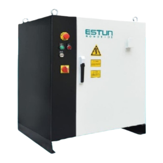
Preface This document primarily provides instructions for the use of the S3E Control Cabinet. The S3E is a standard vertical cabinet. The compatible robot types for this control cabinet are as follows: Control cabinet Type ER150-3200-PR ER220-3200 ER220-3100 ER270-2700 ER270-2850 ER280-3200 ER350-3300 ER350-3300-5... -
Page 15: Table Of Contents
CONTENTS Revision History ..........................4 Safety Precautions ..........................1 Definition of users............................1 Safety Symbols ............................... 1 Safety Precautions ............................2 Safety Precautions ..........................5 Precautions for users ............................5 Safety precautions for robot ..........................7 Ways to stop robot ............................7 Safety precautions for tools and peripheral equipment ................... - Page 16 4.2.1 Connection of teach pendant ......................46 4.2.2 Editing method ..........................46 4.3 Use of ESView software ......................... 47 4.3.1 Connecting the servo drive unit ......................47 4.3.2 Installing ESView ..........................48 4.3.3 Enabling ESView ..........................56 4.3.4 Parameter settings ..........................60 4.4 Definition of parameters .........................
-
Page 17: Chapter 1 Product Information
Chapter 1 Product Information Information on nameplate Figure 1.1 Information on nameplate of electric cabinet Designation (ED3L-ER50) Design Drive Remark Version Series name Model sequence specification Integrated drive system Mark Spec. Mark Compact electrical cabinet Low-load drive Medium-load drive Standard electrical cabinet Heavy-load drive Figure 1.2 Designation... -
Page 18: Preface 10
Components Description of appearance Sticky Lightning Signs Paste the safety warning sign English Paste the safety warning sign Chinese Figure 1.3 Description of appearance Internal structure Inside the control cabinet, multi-core cables should be used for wiring. Avoid leaving excessively long wiring and check for any cable entanglement. -
Page 19: External Interface
Tubular resistor Transformer Figure 1.4 Internal structure External interface Figure 1.5 External interface Basic parameters Table 1-1 Basic parameters list of control cabinet Dimensions(mm) Self-weight Rated power Reference energy consumption Applicable Model (L*W*H) (kg) (kW) (Kw/h) model ER150-3200- 4.65 ERC-S3- 900*694*1150 □□L□... - Page 20 4.65 ER220-3100 4.33 ER270-2700 2.99 ER270-2850 3.53 ER280-3200 3.79 ER350-3300 3.79 ER350-3300-5 4.72 ER500-2800 4.20 ER600-2800 4.20 ER700-2800 Table 1-2 Control cabinet installation parameters Control cabinet installation environment Ventilated, not airtight Minimum installation range 2500*2500*1200 (mm, L*W*H) Ambient working temperature Temperature: 0°...
- Page 21 Item Spec. Storage environment Temperature: -25℃~55℃ Humidity: 95% RH or less (no condensation, no freezing) 100mΩ or more Insulation resistance Vibration strength 4.9m/s² Shock resistance 19.6m/s² Altitude Below 1,000m EMC test standards IEC 61800-3:2017 IP grade IP54...
-
Page 22: Overall Dimensions
1.5 Overall dimensions Figure 1.6 Overall dimensions... -
Page 23: Chapter 2 Transportation & Installation
Chapter 2 Transportation & Installation 2.1 Transportation Handle horizontal control cabinets on pallets during transportation. The operation of cranes, hoists, and forklifts must be carried out by authorized personnel to prevent personal injury and equipment damage. During transportation, avoid vibration, dropping, or impacting the control cabinet. Excessive vibration or impact can have harmful effects on its performance. -
Page 24: Transport By A Forklift
2.1.2 Transport by a forklift When using a forklift to transport the control cabinet, the following precautionary measures should be followed: Ensure a safe working environment for the control cabinet to be safely transported to the ⚫ installation site. Notify personnel working in the forklift's path to be aware of the ongoing movement of the ⚫... -
Page 25: Installation Location
Instructions for users: Please refer to the Instructions for Users and standardize your work. 2.2.2 Installation location ⚫ The control cabinet should be installed outside the range of robot movement (within a safety fence) Security fence Electrical control cabinet Door Range of motion of the robot arm Maximum range of motion of the robot arm, including the end of the tool... - Page 26 ⚫ - There should be a distance of at least 200 mm on both sides of the control cabinet to ensure proper airflow. Top view of the control cabinet Control cabinet door opened ⚫ The control cabinet should be installed at a height between 0.6 meters and 1.72 meters from the ground.
-
Page 27: Chapter 3 Wiring & Connection
Chapter 3 Wiring & Connection ⚫ The system must be electrically grounded to avoid fire, electric shock and bodily injury. ⚫ Turn off the main power switch prior to wiring and inspection to avoid electric shock and bodily injury. ⚫ Be sure to turn off the main power supply for at least 5 minutes prior wiring and inspection. -
Page 28: Residual-Current Circuit Breaker
Piping Wiring duct Wiring ⚫ The wiring and routing of encoder cables must be separated from power cables. If they are placed in the same cable conduit, isolators must be used to keep them separated. Isolator Encoder cable Encoder cable Power cable Power cable Residual-current circuit breaker... -
Page 29: External Interface Definition
External interface definition Figure 3.1 External interface Name Description Mains power cable IO cable interface Undefined input and output signal interfaces (24-pin) RJ45 interface Communication interface to the vision module Encoder cable Motor encoder cable interface for each axis of the robot to collect the robot position signal and connect to the robot body using a special cable. -
Page 30: Basic Diagram
Three-phase power supply wiring Protective earth The input power cable for ESTUN control cabinets is not included and should be wired by the user or purchased from ESTUN. When selecting your own cable, it must comply with the relevant safety regulations. The following cable specifications are recommended based on different control cabinet models. - Page 31 Power harness assembly Connect the power supply incoming terminals on the electrical cabinet, ensuring that the line numbers on the load switch incoming and outgoing terminals match. Figure 1 Securely fasten the green-yellow grounding wire to the grounding copper bar. Figure 2 Figure 3.3 Power harness assembly illustration (3-phase 1) Connect the power supply incoming...
- Page 32 Electrical principle After the three-phase AC is filtered, the three-phase AC 380V voltage is changed to three-phase AC 200V through the transformer (for the electric control cabinet powered by the servo drive with 200V power supply). When there is a temporary power supply frequency interruption or voltage drop, or there is any alarm from the driver, the servo power will be cut off and power will be shut down.
- Page 33 Control power supply 24V Control Power Positive Control power negative Figure 3.6 Control power supply 24V...
- Page 34 Cooling fan EV1~EV3 rear door DC fan Please note! The fan blows air outside the cabinet! Figure 3.7 Cooling fan...
- Page 35 Figure 3.8 Cooling fan (ER150-3200-PR)
- Page 36 DC 24V control loop Servo power-on indication Servo mains control Servo alarm circuit E-stop pendant, provided or not If an external E-stop is required, remove the shorting stub from the terminal Figure 3.9 DC 24V control loop...
- Page 37 AC 220V control loop Servo main contactor control Figure 3.10 AC 220V control loop...
-
Page 38: Teach Pendant
Motor brake Figure 3.11 Motor brake 3.6 Teach pendant 3.6.1 Precautions for using teach pendant Handle with care and avoid dropping, throwing, or striking the teach pendant, as this may cause damage or malfunction. When not in use, hang it on the dedicated holder to prevent accidental dropping (our internal drop test result is satisfactory at a height of 1 meter);... -
Page 39: Apperance Of Teach Pendant
3.6.2 Apperance of teach pendant Figure 3.12 Exterior of the teach pendant Number Description LCD display area Emergency-stop button Mode switch 4a, 4b, 4c Global Function Keys Indicator LED Servo Enable switch Suspension bracket Cable connection area USB interface Operation pen Name Description Processor... -
Page 40: Teach Pendant Interface Definition
Description Name Indicator lights Indicator LEDs: 3 pcs Communication ETHERNET (100M) Accessories Emergency stop; key switch; enable switch (3 digits) Display color quality 16-bit color Power consumption 24V 1A Compatible power supply DC24V 1A and above models Housing material, color ABS/PC;... -
Page 41: Teach Pendant Connection
This product can be equipped with a teach pendant for robot teaching and programming. The connection is illustrated as shown in the figure below. For detailed operation of the teach pendant, please refer to the programming manual of the teach pendant. 3.6.5 Electrical principle ESTUN teach pendant Power supply Emergency stop... -
Page 42: Io Wiring
3.7 IO wiring 3.7.1 IO wiring IO interface definition The figure below shows the aviation plug at body side Definition Definition... -
Page 43: Signal Specifications
Signal specifications The technical specifications of the digital input/output expansion module EC4-1616BWE are shown in the table below. Table 3-2 Table of technical parameters EC4-1616BWE Interface parameters Bus protocol EtherCAT Number of I/O stations Depending on the master Data transmission medium Ethernet/EtherCAT CAT5 cable ≤... - Page 44 Load Maximum output current 250mA Figure 3.14 DO NPN type wiring diagram Figure 3.15 DI PNP type wiring diagram Load Maximum output current 250mA Figure 3.16 DO PNP type wiring diagram Figure 3.17 DI NPN type wiring diagram...
-
Page 45: Encoder Wiring
3.7.2 Encoder wiring Table 3-1 Encoder - Aviation plugs Definition Description Definition Description S1+ S4+ S1﹣ S4﹣ - - Wiring of the J1 motor Wiring of the J4 motor encoder encoder - - 5V-1 5V-4 0V-1 0V-4 S2+ S5+ S2﹣ S5﹣... -
Page 46: Controller
Definition Description Definition Description - - 3.8 Controller The controller is the motion control device of the robot system, which receives instructions from the teach pendant and sends control signals. It is the core component of the system. Status display COM interface LAN interface USB interface... -
Page 47: Communication Connections
Communication connections Extension network port Teach pendant connector Figure 3.18 Communication connections O&M Wizard optional Extension network port Teach pendant connector Figure 3.19 Communication connections (optional O&M wizard) - Page 48 E-stop wiring Figure 3.20 E-stop wiring diagram Wiring terminals E002 and E006 may connect to external emergency stop signals, and wiring terminals E004 and E008 may connect to external emergency stop signals. When there is an external emergency stop or safety door signal, the splice should be removed.
-
Page 49: Input Module
Input module Remote Safety System E- Remote Remote Remote Teach pendant enable Module power supply stop door stop start reset mode EC4-1616B DI part Reload Reserved Module power supply procedure Figure 3.22 Input module Output module Program Excitation Main Visual Remote Reload Teach pendant... -
Page 50: Relay Module
3.9 Relay module The model of the relay module is 11261100001 (relay module ER-Relay-A). Its integrated 18 LED indicators indicate the current status in detail, which has a guiding effect on the maintenance of the internal lines of the control cabinet. Description LED ON LED OFF... - Page 51 The electrical schematic diagram of relay module is shown below. Figure 3.25 Relay module...
-
Page 52: Chapter 4 Debugging
Chapter 4 Debugging 4.1 Checks before power-on Before powering on the control cabinet, please check and confirm the following items, and make necessary adjustments if needed. Content Inspect the appearance of the control cabinet both inside and outside. Check if the fastening screws are securely connected. Verify the status of connectors and installation locations of each unit in the control cabinet. -
Page 53: Use Of Teach Pendant
4.2 Use of teach pendant 4.2.1 Connection of teach pendant “4.2.1 Connection of teach pendant” Please refer to for the connection and wiring method of the teach pendant. 4.2.2 Editing method The modification of drive unit parameters can be completed by following the steps below. Step 1: When the main power is turned on, the control cabinet undergoes an initialization diagnosis. -
Page 54: Use Of Esview Software
Step 5: In the parameter dialog box that appears, set the desired parameters. Please note that the teach pendant can only be used to set certain Pn parameters. If you wish to set more parameters, please use the operating panel. 4.3 Use of ESView software 4.3.1 Connecting the servo drive unit To perform online operations, connect the PC and the servo drive unit using a USB-RS485... -
Page 55: Installing Esview
Plug the MINI USB plug into the drive's CNS Connect the USB plug into the PC Step 6: Rotate the "O-OFF" switch to "I-ON" to power on the control. At this point, the PC has successfully connected to the servo drive unit. 4.3.2 Installing ESView System Requirements Users are required to have a personal computer that meets the following basic conditions:... - Page 56 Please make the following preparations before installation: Windows operating system, communication cable, and decompression software. Log in to the official website of ESTUN at www.estun.com and navigate to the "Downloads" section to find and download the ESView software. If you are unable to obtain the software or require assistance, please contact ESTUN engineers.
- Page 57 For Win10 OS, just right-click Start, and select Device Manager on the pop-up menu. Step 4 An exclamatory mark attaches to the option Other devices > ESTUN USB COMM in Device Manager window, which indicates an error occurs in the driver and needs to update, as shown in Figure Figure 4.2...
- Page 58 Figure 4.3 Update driver Step 6 Click Browse my computer for driver software on the Update Drivers dialog box Figure 4.4 Browse my computer for driver software Step 7 Click Let me pick from a list of available drivers on my computer. Figure 4.5 Let me pick from a list of available drivers on my computer...
- Page 59 Step 8 Click Next. Select your device’s type from the list below Figure 4.6 Step 9 Click Have Disk. Figure 4.7 Have Disk Step 10 Click Browse on the Install From Disk dialog box.
- Page 60 Figure 4.8 Browse files Step 11 Set the Look in as the directory of ESView V4 decompressed file \USB Drivers\windows_drivers on the Locate File dialog box. Step 12 Choose usb_dev_bulk.inf, and then click Open. Figure 4.9 Choose the driver file Step 13 Click OK on the Install From Disk dialog box.
- Page 61 Figure 4.10 Select the driver you want to install for this hardware Step 15 Click Yes on the Update Driver Warning dialog box. Figure 4.11 Confirm the driver updating Step 16 Wait for a while, and then click Install on the Windows Security dialog box. Figure 4.12 Confirm the installation Step17 The driver will be automatically installed to your PC, and then the installation result will be...
- Page 62 Figure 4.13 Complete the USB driver installation...
-
Page 63: Enabling Esview
4.3.3 Enabling ESView Online operation The parameters only can be written into or read from the Drive under the online operation. It is recommended that you perform an online operation for the first time to set the Drive. You need to connect the Drive to the PC by using the USB connection cable before the online operation. - Page 64 Step 6 Select the found device. Figure 4.16 Select the found device If the device is not found in "Search", please check the connection between the device and the PC and make sure that the software version of ESView V4 is up-to-date. Step 7 Click Connect.
- Page 65 Figure 4.18 Device State Now, you can make the necessary settings for the Drive or Motor in real time The Device list can display all the device you had connected or created (including online and offline), and their basic status. ...
- Page 66 Figure 4.19 Select Offline Step 4 Select the desired Device Type, e.g. ED3L. Figure 4.20 Click Connect. Step 5 The created device will be displayed in the Device list on the left of the ESView V4 main windows Figure 4.21 Status of a created device...
-
Page 67: Parameter Settings
⚫ When using offline operation, some functions are restricted and cannot be set correctly. ⚫ Connected online devices or created offline devices are displayed in the “Devices” column. To delete a device, click in the top right, and then click OK on the pop- up warning box. - Page 68 ⚫ Upload All − In the "Parameter Edit" window, click on "Upload All". Wait for a moment, and ESView V4 will read and retrieve all parameter settings from the drive. The retrieved parameters will be displayed in the "Device Values" column. −...
- Page 69 Edit Parameters When the parameters have been uploaded from the device, you can modify them on the Value column. If a value has been modified, the background of the textbox can be changed. Figure 4.24 Display after editing parameters You can refer to the description displayed on the underside of the parameter list for the parameter modification.
- Page 70 Figure 4.26 Save the parameters Step 2 Choose the desired files in the Save As dialog box. Step 3 Click Save. ----End Import Parameters You can fulfill Import function, importing the offline parameters file into the online Drive. Step 1 Select Parameters > Import in the Menu Bar of the ESView V4 main windows Figure 4.27 Select parameters to import Step 2 Select a proper offline parameter file (*.esvpa) in the pop-up Open dialog box.
- Page 71 − Click Download All in the Edit Parameters window. After waiting for a moment, write the edited parameters to the drive. − Right-click the parameters list where cannot be edited, and select Download All in the pop-up menu ⚫ Download the Selected Drag the mouse to select the desired parameters, or you can hold Ctrl key and click the desired parameter, and then right-click a selected parameter, and select Download the Selected in the pop-up menu.
- Page 72 Restore Parameters Executing "Restore Factory Settings" will revert the parameters within the drive unit (except for specific designated parameters) back to their default settings. Please proceed with caution when performing this action. Step 1 Click Restore in the Edit Parameters window. Figure 4.29 Restore parameters Step 2 Read the content on the warning dialog box and click OK.
-
Page 73: Definition Of Parameters
4.4 Definition of parameters Instructions for use When indicating a parameter change, the effective time of the change is as follows: "Restart": The change takes effect only after the power is restored. "Immediately": The change takes effect immediately after the parameter settings are confirmed. Detailed explanation of parameters Servo ON... - Page 74 Detailed explanation of parameters Factory When to Name Scope Unit value take effect - Basic function settings 0 0000~0111 0110 Restart Pn000.0: Servo ON 0 External S-ON is valid External S-ON is not valid. Motor excitation signal Pn000 automatically turned on after /S-RDY output Pn000.1: Reserved Pn000.2: Reserved Pn000.3: Reserved...
- Page 75 Factory When to Name Scope Unit value take effect - Application function settings 5 1000~1301 1000 Restart Pn005.0: Torque Feedforward Method General torque feedforward High-speed torque feedforward Pn005 Pn005.1: Reserved Pn005.2: Deviation alarm enable 0 Disable deviation alarm Enable deviation alarm, triggers an alarm when the deviation counter value exceeds the setting of Pn504 2 Reserved 3 Reserved...
- Page 76 Factory When to Name Scope Unit value take effect - Application function settings 6 0000~0104 0004 Restart Pn006.0: Bus type Not using bus control, but the internal speed parameter control 3 Reserved Pn006 4 Using EtherCAT bus Pn006.1: Reserved Pn006.2: Low-frequency vibration suppression switch 0 Not enabling low-frequency vibration suppression function 1 Enabling low-frequency vibration suppression function Pn006.3: Reserved...
- Page 77 Factory When to Name Scope Unit value take effect - Application function settings 8 0000~0001 0001 Restart Pn008.0: Alarm/warning selection 0 Alarm 1 Warning Pn008 Pn008.1: Axis shielding 0 Axis enable Axis shielding Pn008.2: Reserved Pn008.3: Reserved...
- Page 78 Factory When to Name Scope Unit value take effect - Application function settings 100 0000~0036 0000 Restart Pn100.0: Load Inertia Setting Selection 0 Manually set the percentage of load inertia (Pn106) Use conventional inertia online identification when the load inertia remains unchanged Use conventional inertia online identification when the load inertia changes slightly Use conventional inertia online identification when the load...
- Page 79 Factory When to Name Scope Unit value take effect Immediatel Speed loop gain 1~4000 Pn102 This value determines the magnitude of the speed loop gain. Immediatel Speed loop integral time 1~4096 0.25ms Pn103 Decreasing this value will shorten the positioning time and improve the speed response. Immediatel Position loop gain 0~1000...
- Page 80 Factory When to Name Scope Unit value take effect Immediatel Brake waiting time 10~100 10 ms Pn508 If the delay after servo-off exceeds the value set by this parameter, the /BK signal will be output. The /BK signal will also be output if either the brake waiting speed or the brake waiting time meets the specified conditions.
- Page 81 Factory When to Name Scope Unit value take effect Immediatel - Encoder selection 0000~FF03 0003 Pn840.0: Encoder type 17-bit absolute encoder Pn840 Pn840.1: Reserved Pn840.2: Reserved Pn840.3: Reserved...
-
Page 82: Chapter 5 Troubleshooting
Chapter 5 Troubleshooting 5.1 Alarm check During the operation of the robot, alarms that occur can be viewed using the teach pendant or ESView. Once an alarm occurs, the robot will stop its motion and the user will need to take necessary actions to resolve the issue before resuming robot operation. -
Page 83: Log
⚫ If the current alarm has been cancelled, click "Clear Cur Alarm" button below to clear the current alarm. ⚫ Click on "Historical Alarms" above to go to the "Historical Alarms" tab and click on the "Get Alarms" button to get historical alarm information. 5.2 Log ⚫... -
Page 84: Help
5.3 Help On the Log management screen, you can check whether there are any alarm details on the Help screen. ⚫ On the "Log management" screen, click the "Help" button at the bottom to switch to the "Help" tab. Click "Search box", enter "Alarm number" or "Keyword" and click "Confirm". "Press the "Search" button to find out the detailed information of the alarm. - Page 85 Name Cause of fault Solution ⚫ Check if the electronic gear ratio setting is within the specified range: Input pulse Errors in the drive unit parameter frequency * electronic gear ratio < 500kHz settings, such as improper electronic gear ratio configuration ⚫...
- Page 86 Name Cause of fault Solution Issue with Excessive V-phase current Perform Fn005 operation to bias the current current detection channel and then restore factory settings A.09 channel 1 Replace the servo drive unit Drive unit malfunction Set reasonable PID parameters to avoid Improper drive unit parameter excessive gain causing motor vibration or settings, such as PID parameters...
- Page 87 Check the ambient temperature and reduce the A.18 overheating exceeding the set threshold load alarm Temperature Temperature sensor not connected Please contact ESTUN or an authorized sensor on the or damaged distributor A.1D drive board disconnected Open phase in One phase of the main circuit Ensure correct wiring of the main circuit A.20...
- Page 88 Name Cause of fault Solution Module current Detection of module working Check and reset Pn8403 A.39 exceeds limits current exceeding the set parameters Motor power Incorrect setting of Pn8403 Check and reset Pn8403 level is not A.40 within the specified range Incorrect motor Incompatibility between motor and A.42...
- Page 89 Name Cause of fault Solution Damaged motor Replace the motor Battery not connected or insufficient battery voltage ⚫ Ensure the battery box voltage is 36V Absolute Motor experiencing excessive A.51 encoder detects ⚫ Perform a reset using the Fn010 and Fn011 acceleration due to external reasons overspeed alarm operations...
- Page 90 Name Cause of fault Solution ⚫ Try winding a magnetic ring around the External interference encoder cable and motor power lines (at least three turns) ⚫ Try connecting a wire from the shield layer of the encoder cable to the motor body Serial encoder ⚫...
- Page 91 Name Cause of fault Solution EtherCAT master station Ensure the main station is set with the correct configured with incorrect cycle communication cycle settings EtherCAT A.70 synchronization ⚫ Ensure SYNC0 is synchronized with the SYNC0 not synchronized with the signal error drive unit drive unit ⚫...
-
Page 92: Chapter 6 Maintenance
Chapter 6 Maintenance 6.1 Maintenance precautions Before performing maintenance, please carefully read the following content and ensure a thorough understanding of the methods for safe maintenance. ⚫ Maintenance of the robot system must be carried out by personnel who have received safety training. -
Page 93: Daily Inspection
6.2 Daily inspection To ensure the normal functioning of the product and protect it from damage, it is necessary to perform regular maintenance and inspections. If the equipment is located in the following environments, reduce the inspection interval: Temperature, humidity, dust, and vibration in the environment ... -
Page 94: Items To Confirm During Installation Adjustment
begins to peel Normal operation Visual confirmation, confirmation cleaning Visual confirmation, Filter sponge Dirt and blockage cleaning and replacement Teach pendant console, electric Confirm the function of cabinet indicator light, operation Visual confirmation operation panel, switch, button switch, etc. other operating switches Please make sure that all E-... -
Page 95: List Of Spare Parts
Confirm and set the parameters. Contact emergency stop of operation panel. Confirm the motion of each axis under manual feed. Confirm the signal action of each interface. Confirm the operation of peripheral device control interface signals. 6.5 List of spare parts Table 6-1 List of spare parts of ER220-3200/ER270-2850/ER280-3200 Series Robot ED3L Control Cabinet Material No. - Page 96 13200001469 Straight-end network cable VS-IP20-IP20-LI/0.2-CAT5E 11200000541 Extension module ER-Relay-A-BJ-Relay module 51400000025 Circuit breaker NXB-125 3P D100A 52900000472 Axial flow fan SJ1751HD2BAL 5000RPM 52200000469 IO MODULE EC4-1616BWE(PNP) Tubular resistor 2*(2.5KW20Ω)+2*(2KW20Ω)+2*(5KW12 31661000154 11200000534 ED3L Servo drive ED3L-75DEA-R1[JZ] 11200000471 PRONET Servo drive PRONET-2BDEG-EC-R1[JZ] 11200000533 ED3L Servo drive ED3L-50DEA-R1[JZ] Table 6-4 List of spare parts of ER270-2700 Series Robot ED3L Control Cabinet...
- Page 97 Table 6-6 List of spare parts of ER150-3200-PR Series Robot ED3L Control Cabinet Material No. Name Qty. 51601220924 Transformer (letter) JBK5-800VA,380V.415V/220V 51500000078 AC contactor NXC-50 220V 51400000025 Circuit breaker NXB-125 3P D100A 11200000541 Extension module ER-Relay-A-BJ- Relay module 11200000534 ED3L Servo drive ED3L-75DEA-R1[JZ] 11200000471 PRONET Servo drive PRONET-2BDEG-EC-R1[JZ] * 11200000532...
Need help?
Do you have a question about the S3E Series and is the answer not in the manual?
Questions and answers