Table of Contents
Advertisement
Quick Links
Advertisement
Table of Contents

Related Manuals for Wood-mizer LT70H AH


Summary of Contents for Wood-mizer LT70H AH
- Page 1 Table of Contents Section-Page Table of Contents SW-07doc0328171...
- Page 3 Wood-Mizer ® Safety, Setup, Operation & Maintenance Manual LT70H AH rev. A2.01 LT70H AH WIDE rev. A2.01 Safety is our #1 concern! Read and understand all safety information and instructions before operating, setting up or main- taining this machine. Form #1070...
-
Page 4: Table Of Contents
Table of Contents Section-Page General Contact Information Branches & Authorized Sales CentersWood-Mizer Locations (North and South America) SECTION 1 SAFETY INSTRUCTIONS Safety Symbols..................1-1 Blade Handling..................1-2 Sawmill Setup..................1-2 Sawmill Operation..................1-2 Sawmill Maintenance ................1-4 Safety Instructions ..................1-6 Observe Safety Instructions Wear Safety Clothing Keep Sawmill and Area Around Sawmill Clean Dispose of Sawing By-Products Properly Check Sawmill Before Operation... - Page 5 Table of Contents Section-Page 2.13 Cutting the Log..................2-21 2.14 Edging....................2-22 2.15 Tips on Sawing ..................2-22 2.16 Blade Height Scale ................2-23 2.17 Water Lube Operation ................2-24 2.18 LT70 WIDE Lube System Operation...........2-26 SECTION 3 MAINTENANCE Wear Life....................3-1 Blade Guides ..................3-3 Steel Blade Guide Blocks Antivibration Screw Sawdust Removal ...................3-5 Mast Track, Wiper &...
- Page 6 Table of Contents Section-Page SECTION 5 SAWMILL ALIGNMENT Routine Alignment Procedure ..............5-1 Blade Installation and Positioning Saw Head Tilt Adjustment Blade Guide Arm Alignment Blade Guides Blade Guide Vertical Tilt Adjustment Blade Guide Horizontal Tilt Adjustment Guide Roller Flange Spacing Bed Frame ....................5-13 Levelling the Bed Frame in the Length Direction Levelling the Bed Frame in the Width Direction...
-
Page 7: General Contact Information
Getting Service Wood-Mizer is committed to providing you with the latest technology, best quality and strongest customer service available on the market today. We continually evaluate our customers’ needs to ensure we’re meeting current wood-processing demands. Your comments and suggestions are welcome. -
Page 8: Branches & Authorized Sales Centerswood-Mizer Locations (North And South America)
Branches & Authorized Sales CentersWood-Mizer Locations (North and South America) EUROPE UNITED STATES European Headquarters World Headquarters Wood-Mizer Industries Sp. z o.o. Wood-Mizer LLC Nagórna 114, 62-600 Koło, Poland 8180 West 10th Street Tel.: +48-63-26-26-000 Indianapolis,Indiana 46214-2400, Fax: +48-63-27-22-327 www.woodmizer.eu Tel.: +1-317-271-1542... - Page 9 CROATIA Krešimir Pregernik ITALY Pasquale Felice SERBIA Dragan Markov Pregimex d.o.o. Wood-Mizer Italia Srl Wood-Mizer Balkan d.o.o. S. Batušiæa 31, 10090 Zagreb Cda. Capoiaccio SN Svetosavska GA 3/3; P. Fah 25 Tel.:/Fax: +3851-38-94-668 86012 Cercemaggiore 23 300 Kikinda Krešimir Pregernik Campobasso Tel.:/Fax: +381-230-25-754...
- Page 10 Robert Moxham DENMARK Kevin Christiansen TRANSILVANIEI Nr. 5 Regional Direction - Asia Kevin Christiansen's Sibiu, Cisnadie 555300 Wood-Mizer Asia Manufacturing Co., Ltd. savværker PMV Tel.:/Fax: : +40-369-405-433 No.2, Gongyequ 40th Rd. Xitun District, Arnborgvej 40, 7330 Brande- Fasterholt GSM: +40-745-707-323 Taichung City, 40768, Taiwan, R.O.C.
- Page 11 Sawmill and Customer Identification Each Wood-Mizer sawmill has a 17-digit Vehicle Identification Number (VIN). See the figure below for VIN locations. See the chart for VIN description. F9 017 F9 .01 V.I.N. DESCRIPTION V.I.N. LOCATIONS HDSdoc040622...
- Page 12 Each sawmill is also identified with a model number which includes the base model and the engine/motor configuration. See the figure for a description of the model number. LT70 Engine/Motor Basic Sawmill I.D. Configuration MODEL NUMBER DESCRIPTION When you pick up your mill, you will receive a customer number. Both the VIN and your customer number expedite our service to you.
-
Page 13: Safety Instructions
Always be sure that all safety decals are clean and readable. Replace immediately all damaged safety decals to prevent personal injury or damage to the equipment. Contact Wood-Mizer Customer Service or the Wood-Mizer distributor in your area to order a new decal. -
Page 14: Blade Handling
Safety Instructions Blade Handling Blade Handling DANGER! Always disengage the blade and shut off the sawmill motor before changing the blade. Failure to do so will result in serious injury. WARNING! Always wear gloves and eye protection when handling bandsaw blades. Keep all other persons away from area when coiling, uncoiling, carrying or changing a blade. - Page 15 Safety Instructions Sawmill Operation DANGER! Always be sure the blade is disengaged and all persons are out of the path of the blade before starting the motor. Failure to do so may result in serious injury. DANGER! Keep all persons out of the path of boards being removed. Failure to do so may result in serious injury.
-
Page 16: Sawmill Maintenance
Safety Instructions Sawmill Maintenance CAUTION! Be careful when manually lowering the log loader. Do not drop the loader onto the ground or perform any action which might break the velocity fuse valves on the loader cylinders. These valves control oil flow and are necessary to prevent the loading arms from collapsing during use. - Page 17 Safety Instructions Sawmill Maintenance WARNING! Drum switch grease contains Petroleum Hydrocarbon Lubricant. Eye and skin irritant. If introduced into eyes, flush with water for at least 15 minutes. If film or irritation persists, seek medical attention. Wash your skin with soap and water. If ingested, do not induce vomiting - contact a physician.
-
Page 18: Observe Safety Instructions
It is always owner's responsibility to comply with all applicable federal, state and local laws, rules and regulations regarding the ownership and operation of your Wood-Mizer sawmill. All Wood-Mizer owners are encouraged to become thoroughly familiar with these applicable laws and comply with them fully while using the sawmill. -
Page 19: Wear Safety Clothing
Safety Instructions Wear Safety Clothing Wear Safety Clothing WARNING! Secure all loose clothing and jewelry before operating the sawmill. Failure to do so may result in serious injury or death. WARNING! Always wear gloves and eye protection when handling bandsaw blades. Changing blades is safest when done by one person! Keep all other persons away from area when coiling, carrying or changing a blade. -
Page 20: Check Sawmill Before Operation
Safety Instructions Check Sawmill Before Operation Check Sawmill Before Operation DANGER! Make sure all guards and covers are in place and secured before operating the sawmill. Failure to do so may result in serious injury. Keep Persons Away DANGER! Keep all persons out of the path of moving equipment and lumber when operating the sawmill. -
Page 21: Keep Hands Away
Safety Instructions Keep Hands Away Keep Hands Away DANGER! Always shut off the blade motor before changing the blade. Failure to do so may result in serious injury. DANGER! Motor components can become very hot during operation. Avoid contact with any part of a hot motor. Contact with hot motor components can cause serious burns. -
Page 22: Use Proper Maintenance Procedures
Safety Instructions Use Proper Maintenance Procedures Use Proper Maintenance Procedures DANGER! Make sure all electrical installation, service and/or maintenance work is performed by a qualified electrician and is in accordance with applicable electrical codes. DANGER! Hazardous voltage inside the electric boxes and at the motor can cause shock, burns, or death. -
Page 23: Keep Safety Labels In Good Condition
Safety Instructions Keep Safety Labels in Good Condition CAUTION! The operator workstation should be equipped with a 4 kg or bigger dry powder extinguisher. Keep Safety Labels in Good Condition IMPORTANT! Always be sure that all safety decals placed on the machine are clean and readable. - Page 24 Safety Instructions Keep Safety Labels in Good Condition TABLE 1-1 099221 CAUTION! Keep all persons away from the machine during sawmill operation. 099221 098176 CAUTION! Keep away from the debarker blade! 098176 096316 CAUTION! Do not open or close the electric box when the switch is not in the ”0”...
- Page 25 Safety Instructions Keep Safety Labels in Good Condition TABLE 1-1 096319 CAUTION! Disconnect power supply before opening the box. 086099 CAUTION! Hot parts - keep a safe distance! 086099 099222 CAUTION! Sawdust falling out - protect your eyes! 096321 Blade movement direction 505189 Position of the tensioner ball valve lever 505189...
- Page 26 Safety Instructions Keep Safety Labels in Good Condition TABLE 1-1 512240 Clean the chain every 50 hours of sawmill operation or once a week. 512240 512158 Lubricate the chain every 50 hours of sawmill operation or once a week. 512158 S12004G CAUTION! Always wear safety goggles when operating the sawmill!
- Page 27 Safety Instructions Keep Safety Labels in Good Condition TABLE 1-1 501465 CAUTION! Always wear safety boots when operating the sawmill! 501467 Lubrication point P11789-70 Tracking the blade on the blade wheels P11789-70 P85070 CE certification marking 099401 Russian safety certification 099401 S20097E 2930 r.p.m.
-
Page 28: Belt Sizes
Safety Instructions Belt Sizes Belt Sizes See Table 1-2. See the table below for sizes of the belts used on the LT70 sawmills. Description Belt Size PART # Motor Drive Belt (E25) 3B/HB 089464 2462La Up/Down Drive Belt (AC sawmills only) HA-670 091328 Blade Pulley Belts... -
Page 29: Blade Motor Specifications
1LE1002-1DA63-4AA4-Z (30 HP) The electric motors supplied on Wood-Mizer sawmills carry a rating assigned by the motor manufacturer for the continuous duty operation of the motor, potentially, 24 hours per day, day after day. This rating is useful in sizing motors for use in applications like blowers for cooling and ventilation that are never cycled off except for system maintenance. -
Page 30: Noise Level
Safety Instructions Noise Level 1.11 Noise Level See Table 1-6. The noise exposure level is given in the table below Sawmill Noise Level L LT70 E15 AH 87,1 dB (A) LT70 E20 AH 87,1 dB (A) LT70 E30 AH -- (A) TABLE 1-6 1.12 Overall Dimensions See Table 1-7. -
Page 31: Chains
Safety Instructions Chains See Figure 1-1. The figure below shows the LT70H sawmill dimensions. FIG. 1-1 1.13 Chains See Table 1-8. The load capacity of the chains is given below. Load Capacity According to ISO Nr 08A-1 Power Feed Chain 22700N Up/Down Chain 45400N... -
Page 32: Lube System Specifications
Safety Instructions Lube System Specifications 1.14 Lube System Specifications See Table 1-9. The blade lubricating oil specifications are listed below. Oil Type Manufacturer Freezing Ignition Autoignition Temperature Temperature Temperature Orlen Above 140 C 250 C (482 F) ACP-1E -20 C (-4 F ... -
Page 33: Sawmill Components
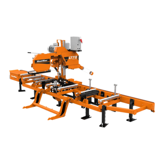
Safety Instructions Sawmill Components 1.16 Sawmill Components See Figure 1-2. The major components of the LT70H sawmill are shown below. A - Saw Head, B - Blade Drive Motor Assembly, C - Bed Frame, D - Hydraulic Box, E - Control Box, F - Electric Box, G - Log Loader, H - Belt Conveyor FIG. -
Page 34: Setup & Operation
SETUP & OPERATION Sawmill Setup SECTION 2 SETUP & OPERATION Sawmill Setup IMPORTANT! Before starting to use the sawmill you have to meet the following conditions: Set up the machine on firm and level ground. Level the sawmill. Secure the sawmill to the ... - Page 35 SETUP & OPERATION Sawmill Setup The sawmill’s operator position is shown below. FIG. 2-0 CAUTION! To immediately stop the blade and feed motors, press the E-STOP button. Turn this button clockwise to release the stop. WARNING! If the blade or drive belt breaks, wait until all moving parts stop completely.
-
Page 36: Sawmill Setup
SETUP & OPERATION Bed Frame Leveling Have a qualified electrician install the power supply (according to EN 60204 Standard). The power supply must meet the specifications given in the table below. 3-Phase Circuit Breaker Recommended Volts Wire Size 15kW 400 VAC 32 A 6 mm... - Page 37 SETUP & OPERATION Bed Frame Leveling difference of the four dimensions taken. See Table 2-1. Suppose the four dimensions from track rail to the laser beam are as shown below. The 133.4mm [5 1/4”] dimension should be the target dimension as this will require the least adjustment at each location.
- Page 38 SETUP & OPERATION Bed Frame Leveling See Figure 2-3. Then level the bed frame in the horizontal plane. To do this, first place two pieces of straight tubing between the front two bed rail supports. Next, measure from the front end of each tube to the laser beam.
-
Page 39: Track Rail Wiper
SETUP & OPERATION Track Rail Wiper Track Rail Wiper Before operating the sawmill do as follows: 1. Clean the upper and lower rails to remove any sawdust and rust preventives. 2. Unbolt and remove the track wiper cover. 3. Soak the felt wiper with Dexron III transmission fluid, 10W30 motor oil or 3-in-1 turbine oil. 4. -
Page 40: Replacing The Blade
SETUP & OPERATION Replacing the Blade Replacing the Blade DANGER! Always disengage the blade and shut off the sawmill motor before changing the blade. Failure to do so may result in serious injury. WARNING! Always wear gloves and eye protection when handling bandsaw blades. -
Page 41: Tensioning The Blade
SETUP & OPERATION Tensioning the Blade Tensioning the Blade Before tensioning the blade, check on the air pressure gauge that the air pressure in the air bag is correct. The gauge should read 44 psi, i.e. .3 MPa (yellow colour) with the blade tension completely released. -
Page 42: Tracking The Blade
SETUP & OPERATION Tracking the Blade See Table 2-2. The recommended tension for different types of blades is shown below. Blade Type Blade Size Tension Range Thickness (mm) Width (mm) 2735 1.07 60-62 0.41-0.43 3735 1.14 0.45 1.07 60-62 0.41-0.43 1.14 62-65 0.43-0.45... - Page 43 SETUP & OPERATION Tracking the Blade SM0044D 3.0 mm (0.12”) ± 1 mm (0.04”) 4.5 mm (0.18”) 1 1/4" ± 1 mm (0.04”) Blade 1 1/2" Blade FIG. 2-6 4. Use the cant control bolt to adjust where the blade travels on the blade wheels. See Figure 2-7.
-
Page 44: Starting The Motor
SETUP & OPERATION Starting the Motor NOTE: Slight adjustments of the side bolts on the outer blade wheel are usually all that is necessary to track the blade properly. See Section 7.4 for complete blade wheel alignment instructions. 5. Adjust the blade tension if necessary to compensate for any changes that may have occurred while adjusting the cant control. - Page 45 SETUP & OPERATION Starting the Motor DANGER! Check the sawmill wiring every year. Make sure all electrical installation, service and/or maintenance work is performed by a qualified electrician. WARNING! Hazardous voltage inside the electric box is dangerous. Turn the main switch to the OFF (“0”) position and lock out power supply before opening the box door! WARNING! The door of the electric box can be opened only when the...
-
Page 46: Hydraulic Control Operation
SETUP & OPERATION Hydraulic Control Operation Hydraulic Control Operation The hydraulic control levers become operational when the contacts at the bottom of the saw head touch the power supply strip on the frame tube. The saw head must be close enough to the front end of the sawmill to touch the power supply strip. -
Page 47: Loading, Turning And Clamping Logs
SETUP & OPERATION Loading, Turning and Clamping Logs 1. Move the clamp out and down so it will not get in the way of logs being loaded onto the bed. Using the clamp in/out lever, move the clamp toward the loading side of the sawmill. Use the clamp up/down lever to lower the clamp below the bed level. - Page 48 SETUP & OPERATION Loading, Turning and Clamping Logs enough forward so the log does not hit it. Failure to do so may result in machine damage. CAUTION! Be sure the log clamp, turner and toe boards are lowered completely before loading a log onto the bed. Failure to do so may result in machine misalignment or damage.
- Page 49 SETUP & OPERATION Loading, Turning and Clamping Logs 6. Disengage the clamp. 7. The log can be turned now. Repeat the steps 4 through 7 until the log is turned as desired. Turning Small Cants (Optional Procedure) To turn a small cant, you may use the main clamp. 1.
-
Page 50: Up/Down Operation
SETUP & OPERATION Up/Down Operation 2.10 Up/Down Operation This section describes operation of the up/down system with the standard controls. See the Setworks or Accuset manual for operation of the up/down system with this controller. 1. Install a blade, if needed, and check for correct blade tension (See Section 2.5). -
Page 51: Blade Guide Arm Operation
SETUP & OPERATION Blade Guide Arm Operation 2.11 Blade Guide Arm Operation 1. Look down the length of the log to see its maximum width. The outer blade guide should be adjusted to clear the widest section of the log by less than 1" (25.4 mm). 2. -
Page 52: Power Feed Operation
SETUP & OPERATION Power Feed Operation 2.12 Power Feed Operation See Figure 2-11. The power feed system moves the saw head forward and backward by using two switches on the control panel. Head Forward Head Reverse Feed Rate Adjustment FIG. 2-11 Feed Rate Adjustment The saw head feed rate switch controls the speed at which the saw head travels forward. - Page 53 SETUP & OPERATION Power Feed Operation WARNING! Be sure the power feed switch is in the neutral position before turning the key switch to the position #3 or #2. This prevents accidental saw head movement, which may cause serious injury or death.
-
Page 54: Cutting The Log
Cutting the Log 2.13 Cutting the Log The following steps guide you through normal operation of the Wood-Mizer sawmill. 1. Once the log is placed where you want it and clamped firmly, turn the key switch to the position #1. -
Page 55: Edging
Edging 2.14 Edging The following steps guide you through edging boards on the Wood-Mizer sawmill. 1. Raise the side supports to 1/2 the height of the boards that need to be edged. 2. Stack the flitches on edge against the side supports. -
Page 56: Blade Height Scale
SETUP & OPERATION Blade Height Scale 2.16 Blade Height Scale See Figure 2-12. The blade height scale is attached to the saw head frame. It includes: a blade height indicator, a metric/inch scale, a quarter scale. Blade Height Wskaźnik wysokości Metric Quarter Skala metryczna... -
Page 57: Water Lube Operation
SETUP & OPERATION Water Lube Operation Check that these items are below the blade level before sawing. Quarter Scale See Table 2-3. Two quarter scales are provided with four sets of marks. Each set represents a specific lumber thickness. Saw kerf and shrinkage allowance are included, but actual board thickness will vary slightly depending on blade thickness and tooth set. - Page 58 SETUP & OPERATION Water Lube Operation in the bottle cap controls the amount of water flow. Turn valve By otworzyć zawór należy obrócić go counterclockwise w kierunku przeciwnym do ruchu wskazówek zegara; by zamknąć - w kierunku zgodnym to open; clockwise to close z ruchem wskazówek zegara.
-
Page 59: Lt70 Wide Lube System Operation
SETUP & OPERATION LT70 WIDE Lube System Operation 2.18 LT70 WIDE Lube System Operation See Figure 2-14. The Lube System keeps the blade clean during sawing. When the shut-off valve (A) is open, the coolant (ACP-1 oil) flows from the tank (B) through the hoses to surfaces of the wheels. -
Page 60: Maintenance
MAINTENANCE Wear Life SECTION 3 MAINTENANCE This section lists the maintenance procedures that need to be performed on the LT70H sawmills. CAUTION! Always disconnect and lock out power supply before performing any maintenance work, cleaning or servicing the sawmill. Failure to do so may result in serious injury. The Short Interval Maintenance Schedule lists procedures that need to be performed every 4, 8 or 24 hours. - Page 61 MAINTENANCE Wear Life Chain Log Turner – Changing Sprockets 1500 hours and Chain Self-Lubricating Bushings 1500 hours TABLE 3-1 MAINTENANCE doc040622...
-
Page 62: Blade Guides
MAINTENANCE Blade Guides Blade Guides 1. Check the blade guide rollers for performance and wear at every blade change. Make sure the rollers are clean and spinning freely. If not, rebuild them. Replace any rollers which have worn smooth or have become cone shaped. Steel Blade Guide Blocks 2. - Page 63 Preventing sap buildup on the blade is critical when using the high-performance blade guide system. If the wood you are sawing leaves sap buildup, you can add the Wood-Mizer lube additive (Part No. 033439) to plain water in the blade lube system.
-
Page 64: Antivibration Screw
MAINTENANCE Sawdust Removal Antivibration Screw Make sure the antivibration screw in the top center of the C-frame is 1.5 mm (1/16") away from the blade.. If not, loosen the nut and adjust the screw as necessary. Check the distance between the antivibration screw and the blade at every blade change. - Page 65 MAINTENANCE Mast Track, Wiper & Scrapers Remove the track roller housing covers and brush any sawdust buildup from the housings. 3. Check the track scrapers as needed. Make sure the scrapers fit firmly against the rail. If a track scraper needs to be adjusted, loosen the thumb screw, push the scraper downward until it fits firmly against the rail, and retighten the thumb screw.
-
Page 66: Vertical Mast Rails
Lubricate the up/down and power feed drum switch contacts inside the control panel every fifty hours of operation. Use only contact grease supplied by Wood-Mizer. Remove the control box cover. Use a cotton swab to apply grease to the switch contact ends. -
Page 67: Motor Drive Belt Adjustment
MAINTENANCE Motor Drive Belt Adjustment Motor Drive Belt Adjustment DANGER! Never adjust the motor drive belt while the motor is running. Failure to do so may result in serious injury. Periodically check the drive belt for wear. Replace any damaged or worn belts as needed. See Figure 3-4. -
Page 68: Up/Down System
MAINTENANCE Up/Down System Up/Down System Adjust the up/down chain tension as needed. Measure the chain tension with the head all the way to the top of the vertical mast. Find the chain adjustment bolt at the bottom of the mast. Use the adjustment nut to adjust the bolt until the center of the chain can be deflected 3/4”... - Page 69 Śruby regulacyjne Adjustment Bolts 80_105 Mounting Śruby Bolts montażowe FIG. 3-4 Periodically check the belt for wear. Replace any damaged or worn belts as needed. If oil leaks from the gear reducer, please contact Wood-Mizer Customer Service. MAINTENANCE doc040622 3-10...
-
Page 70: Power Feed System
MAINTENANCE Power Feed System 3.10 Power Feed System 1. Adjust the power feed chain as needed. Measure the power feed chain tension with the saw head all the way toward the front of the mill. Use the two lock nuts at the rear of the mill to tighten or loosen the power feed chain. -
Page 71: Safety Devices Inspection
MAINTENANCE Safety Devices Inspection TEMPERATURE -30° -20° -10° 0° 10° 20° 30° 40° 50° 60° 70° 80° 90° 100° 110° 120° -35° -29° -23° -18° -12° -7° -1° 5° 10° 16° 21° 27° 32° 38° 44° 49° Level A Fluid Level B Fluid Level C Fluid HD0049B... - Page 72 MAINTENANCE Safety Devices Inspection Saw Head Up Saw Head Forward Saw Head Down Saw Head Reverse Debarker Motor On/Off Debarker Arm In/Out Board Return Emergency System On/Off Stop Button Blade Guide Arm In/Out Blade Motor Key Switch Blade Motor 3H0280_ac1 START/STOP 2.
- Page 73 MAINTENANCE Safety Devices Inspection 3. Blade cover safety switch #1 and its circuit inspection Start the motor; Open the blade housing cover #1; The motor should stop; Try to start the motor. It should not be possible to start the motor. ...
- Page 74 MAINTENANCE LOG (Check Engine And Option Manuals For Additional Maintenance Procedures) Check Blade Screw See Section 5.2 Daily - Every Blade Change Check Blade Guide Performance See Section 5.2 Daily - Every Blade Change Remove Excess Sawdust From Blade Wheel Hous- See Section 5.3 Daily - Every Blade Change DAILY MAINTENANCE PROCEDURES...
- Page 75 MAINTENANCE LOG (Check Engine And Option Manuals For Additional Maintenance Procedures) TOTAL HOURS OF OPERATION MANUAL FILL IN THE DATE AND THE MACHINE HOURS AS YOU PERFORM EACH PROCEDURE. PROCEDURE REFERENCE A SHADED BOX INDICATES MAINTENANCE IS NOT NEEDED AT THIS TIME. 550 HRS 600 HRS 650 HRS...
- Page 76 MAINTENANCE LOG (Check Engine And Option Manuals For Additional Maintenance Procedures) TOTAL HOURS OF OPERATION MANUAL FILL IN THE DATE AND THE MACHINE HOURS AS YOU PERFORM EACH PROCEDURE. PROCEDURE REFERENCE A SHADED BOX INDICATES MAINTENANCE IS NOT NEEDED AT THIS TIME. 1050 HRS 1100 HRS 1150 HRS...
- Page 77 MAINTENANCE LOG (Check Engine And Option Manuals For Additional Maintenance Procedures) TOTAL HOURS OF OPERATION MANUAL FILL IN THE DATE AND THE MACHINE HOURS AS YOU PERFORM EACH PROCEDURE. PROCEDURE REFERENCE A SHADED BOX INDICATES MAINTENANCE IS NOT NEEDED AT THIS TIME. 1550 HRS 1600 HRS 1650 HRS...
- Page 78 MAINTENANCE LOG (Check Engine And Option Manuals For Additional Maintenance Procedures) TOTAL HOURS OF OPERATION MANUAL FILL IN THE DATE AND THE MACHINE HOURS AS YOU PERFORM EACH PROCEDURE. PROCEDURE REFERENCE A SHADED BOX INDICATES MAINTENANCE IS NOT NEEDED AT THIS TIME. 2050 HRS 2100 HRS 2150 HRS...
- Page 79 MAINTENANCE LOG (Check Engine And Option Manuals For Additional Maintenance Procedures) TOTAL HOURS OF OPERATION MANUAL FILL IN THE DATE AND THE MACHINE HOURS AS YOU PERFORM EACH PROCEDURE. PROCEDURE REFERENCE A SHADED BOX INDICATES MAINTENANCE IS NOT NEEDED AT THIS TIME. 2550 HRS 2600 HRS 2650 HRS...
-
Page 80: Troubleshooting
Troubleshooting Sawing Problems SECTION 4 TROUBLESHOOTING Sawing Problems PROBLEM CAUSE SOLUTIOIN Blades dull quickly Dirty logs Clean or debark logs, especially on the entry sides of the cut. The blade teeth heated too much Grind just enough metal to restore during sharpening sharpness to the teeth. - Page 81 Troubleshooting Sawing Problems PROBLEM CAUSE SOLUTION Boards thick or thin on ends Stress in the log which causes the log After the log has been squared, take or middle of boards to not lay flat on the bed equal cuts off the opposing sides. Take a board off the top.
-
Page 82: Electrical Problems
NOTE: Use only contact grease supplied by Wood-Mizer. Drum switch spring broken Manually move the power feed or up/down switch back to the neutral or "off” position. -
Page 83: Power Feed Problems
The drum switch is dirty. Clean the drum switch and lubricate with the speeds or does not move until contact grease supplied by Wood-Mizer. speed is above halfway mark. The drum switch contacts are Check that the contacts are in good condition bad. - Page 84 Troubleshooting Power Feed Problems PROBLEM CAUSE SOLUTION The power feed motor The middle track oiler is Clean and lubricate the middle track oiler. Allow overheats. dragging. the motor to cool before restarting. The sawmill ground is not Level the sawmill. Allow the motor to cool level.
-
Page 85: Hydraulic Problems
Troubleshooting Hydraulic Problems Hydraulic Problems PROBLEM CAUSE SOLUTION You can actuate any hydraulic Saw head not positioned Move the mast so that it contacts the power handle, but get no response properly to provide drive supply strip. Check the contacts and strip for from the pump. - Page 86 Troubleshooting Hydraulic Problems PROBLEM CAUSE SOLUTION Low fluid level Check the fluid level. Add an all-season hydraulic fluid such as Amoco Rycon Oil MV, Mobil Multipurpose ATF (automatic transmission fluid) or Exxon/Esso Univis J26 until the level is 4 - 4 1/2" from the bottom of reservoir with all cylinders retracted.
- Page 87 Troubleshooting Hydraulic Problems PROBLEM CAUSE SOLUTION Hydraulic side supports go Dirt in the sequence valve Remove the sequence valve and clean down before or at same time thoroughly with kerosene. NOTE: Be sure to as log turner. reassemble the valve and install it in its original position on the cylinder.
-
Page 88: Motor Pulley Alignment
Troubleshooting Motor Pulley Alignment Motor Pulley Alignment 1. Install the drive belt. 2. Use a straight edge to align the motor pulley to the blade drive pulley. Check if the motor pulley is aligned with the blade drive pulley. Loosen the bolts in the motor mount plate and move the motor if necessary. -
Page 89: Power Feed Mechanical Test
Troubleshooting Power Feed Mechanical Test Power Feed Mechanical Test 1. Remove the weight from the track rollers. They should turn smoothly and easily with very little play. 2. Make sure the middle track cover is not bent or touching the top rail. 3. -
Page 90: Circuit Breaker Operation
Troubleshooting Circuit Breaker Operation Circuit Breaker Operation The cawmill controls are equipped with manual reset circuit breakers to protect the electrical circuits. Patrz rysunek 4-1. The blade guide and accessory circuit breakers are located inside the control box. Remove the circuit breaker panel from the control box to access the internal breakers NOTE: If the breaker is still hot, you may not be able to reset it immediately. -
Page 91: Sawmill Alignment
Routine Alignment Procedure SECTION 5 SAWMILL ALIGNMENT The Wood-Mizer sawmill is factory aligned. Two alignment procedures are available to realign the sawmill if necessary. The Routine Alignment instructions should be performed as necessary to solve sawing problems not related to blade performance. The Complete Alignment procedure should be performed approximately every 1500 hours of operation (sooner if you regularly transport the sawmill over rough terrain). -
Page 92: Saw Head Tilt Adjustment
Sawmill Alignment Routine Alignment Procedure Saw Head Tilt Adjustment As the blade enters a wide log or cant, the outside of the saw head will drop down slightly. compensate for the drop, the saw head is adjusted 1/26" (1 mm) higher at the outside. 1. - Page 93 Sawmill Alignment Routine Alignment Procedure higher than the inside. Retighten the retaining plate bolts. 600011-4a Adjustment Bolt Śruba regulacyjna Śruby w płycie Retaining Plate Adjustment Bolt Śruba regulacyjna Bolts Stop Bolt prowadnicy Śruba kontrująca suwaka Tighten adjustment Dokręcić śruby bolts to raise saw regulacyjne, by head;...
-
Page 94: Blade Guide Arm Alignment
Sawmill Alignment Routine Alignment Procedure Blade Guide Arm Alignment The blade guide arm moves the outer blade guide in and out. If the arm becomes loose, the blade guide will not guide the blade properly, causing inaccurate cuts. A loose blade guide arm can also cause blade vibration. - Page 95 Sawmill Alignment Routine Alignment Procedure See Figure 5-4. Measure distance between roller flange and Zmierzyć odległość pomiędzy kołnierzem rolki prowadzącej blade with arm open and closed piłę a piłą przy ramieniu prowadnika piły przesuniętym w kierunku wewnętrznym oraz zewnętrznym. 3H0802-10b FIG.
- Page 96 Sawmill Alignment Routine Alignment Procedure See Figure 5-6. Measure from blade guide arm to bed rail with arm open and closed FIG. 5-6 7. Adjust the blade guide arm to 1/2" (15 mm) from fully open. Measure the distance from the blade guide mounting block to the bed rail.
- Page 97 Sawmill Alignment Routine Alignment Procedure tighten the right bolt. Retighten the jam nuts and recheck the blade guide arm vertical tilt. Left Vertical Adjustment Bolt Right Vertical Adjustment Bolt FIG. 5-7 Sawmill Alignment HDSdoc040622...
-
Page 98: Blade Guide Vertical Tilt Adjustment
Sawmill Alignment Routine Alignment Procedure Blade Guide Vertical Tilt Adjustment The blade guides should be adjusted properly in the vertical plane. If the blade guides are tilted vertically, the blade will try to travel in the tilted direction. A Blade Guide Alignment Tool (BGAT) is provided to help you measure the vertical tilt of the blade. 1. -
Page 99: Blade Guide Horizontal Tilt Adjustment
Sawmill Alignment Routine Alignment Procedure and tighten the bottom screw. Tighten the jam nuts and recheck the tilt of the blade. Top Vertical Tilt Górny wkręt regulacji pochylenia Adjustment Screw w płaszczyźnie pionowej 600034b Adjust screws down to tilt Regulować wkręty w dół, roller up;... - Page 100 Sawmill Alignment Routine Alignment Procedure See Figure 5-10. Wkręty regulacyjne pochylenia w Horizontal Tilt Adjust- płaszczyźnie poziomej ment Screws Blade Guide Przyrząd do regulacji Alignment Tool prowadnika piły FIG. 5-10 3. Measure between the back edge of the blade and the tool at the end closest to the inner blade guide ("B").
- Page 101 Sawmill Alignment Routine Alignment Procedure the right screw. Tighten the jam nuts and recheck the tilt of the blade. Adjust screws right to tilt roller left; adjust screws left to tilt roller right FIG. 5-11 5. Repeat the above steps for the inner blade guide assembly. NOTE: Once the blade guides have been adjusted, any cutting variances are most likely caused by the blade.
-
Page 102: Guide Roller Flange Spacing
Sawmill Alignment Routine Alignment Procedure Guide Roller Flange Spacing Each blade guide must be adjusted so the roller flange is the correct distance from the back edge of the blade. If the flange is too close to or too far from the blade, the sawmill will not cut accurately. HINT: When adjusting the blade guide spacing, loosen the top set screw and one side set screw only. -
Page 103: Bed Frame
Sawmill Alignment Routine Alignment Procedure Bed Frame 5.2.1 Levelling the Bed Frame in the Length Direction NOTE: In some cases, when the ground has a large tilt, leg adjustment may not be sufficient to level the bed frame in the vertical plane. In such a case, level the sawmill as much as possible. -
Page 104: Side Support Adjustment
Sawmill Alignment Routine Alignment Procedure and reapeat the adjustment steps described above. Level Position ‘B’ Level Position ‘A’ Straight Adjustment Tubes (2) FIG. 5-4 5.2.5 Side Support Adjustment See Figure 5-6. Place square adjustment tubes (Part No. S12831 - 2 required) across the bed rails in front of one of the side supports. - Page 105 Sawmill Alignment Routine Alignment Procedure bed or tilted slightly forward 1/32” (0.8 mm). Adjust the tilt of the side support if necessary. Place square Place square against side against side support support Adjustment Alignment Adjustment Adjustment Tubes (2) Tubes (2) Nuts Nuts 300_0220-4...
-
Page 106: Blade Height Scale Adjustment
Sawmill Alignment Routine Alignment Procedure Blade Height Scale Adjustment After the entire sawmill has been aligned and all adjustments have been made, check that the blade height scale indicates the true distance from the blade to the bed rails. To do this: 1. -
Page 107: Complete Alignment Procedure
Sawmill Alignment Complete Alignment Procedure Complete Alignment Procedure Bed Frame Setup Before performing the following alignment procedures, setup the mill on firm, level ground. Lower the sawmill feet so the weight of the sawmill is evenly supported. Blade Installation and Positioning 1. -
Page 108: Blade Wheel Alignment
Sawmill Alignment Complete Alignment Procedure Blade Wheel Alignment The blade wheels should be adjusted so they are level in the vertical and horizontal planes. If the blade wheels are tilted up or down, the blade will want to travel in the tilted direction. If the blade wheels are tilted horizontally, the blade will not track properly on them. - Page 109 Sawmill Alignment Complete Alignment Procedure Adjust vertical adjustment screws up to tilt drive-side Aby pochylić koło prowadzące strony czynnej w dół, blade wheel down. Adjust screws down to tilt wheel należy wyregulować śruby regulacji pionowej w górę; aby pochylić koło w górę - śruby wyregulować w dół FIG.
- Page 110 Sawmill Alignment Complete Alignment Procedure Adjust vertical adjustment screws up to tilt idle-side blade wheel down; adjust screws down to tilt wheel up FIG. 5-10 8. Recheck the vertical tilt of the idle-side blade wheel with the blade guide alignment tool. Readjust the blade wheel as necessary until the front and rear of the tool are the same distance from the bed rail (within 1/16"...
- Page 111 Sawmill Alignment Complete Alignment Procedure 9. Check the position of the blade on the idle-side blade wheel. See Figure 5-11. The horizontal tilt of the blade wheel should be adjusted so that the gullet of a 1-1/4" blade is 1/8" (3 mm) out from the front edge of the wheel (± 1,5 mm). The gullet of a 1-1/2" blade should be 3/16"...
- Page 112 Sawmill Alignment Complete Alignment Procedure 10. Check the position of the blade on the drive-side blade wheel. The blade should be positioned on this wheel as described for the idle-side blade wheel. If not, adjust the drive wheel horizontally. See Figure 5-13. Use the horizontal adjustment screw to adjust the drive-side blade wheel. To move the blade back on the wheel, loosen the jam nut on the adjustment screw and tighten the screw.
- Page 113 Sawmill Alignment Complete Alignment Procedure necessary. Retighten the retaining plate bolts. 600011-4a Adjustment Bolt Śruba regulacyjna Śruby w płycie Retaining Plate Adjustment Bolt Śruba regulacyjna Stop Bolt prowadnicy Bolts Śruba kontrująca suwaka Tighten adjustment Dokręcić śruby bolts to raise saw regulacyjne, by head;...
- Page 114 Sawmill Alignment Complete Alignment Procedure See Figure 5-15. Blade Bed Rails Clamping Bolt Clamping Bolt Adjustment Adjustment Bolt Adjustment Bolt Bolt SM0064_D FIG. 5-15 15. Without adjusting the saw head height, check the three remaining main bed rails. Adjust them so that all measure the same distance from the blade at both ends of the bed rail.
-
Page 115: Blade Guide Installation
Complete Alignment Procedure Blade Guide Installation Each Wood-Mizer sawmill has two blade guide assemblies that help the blade maintain a straight cut. The two blade guide assemblies are positioned on the saw head to guide the blade on each side of the material being cut. -
Page 116: Blade Guide Arm Alignment
Sawmill Alignment Complete Alignment Procedure NOTE: Before adjusting the top bolt, unload pressure on the bolt by turning 1/2 turn in the opposite direction it was last adjusted. With the roller flange positioned properly from the back of the blade, adjust the rear bolt so it touches the end of the blade guide mounting shaft. - Page 117 Sawmill Alignment Complete Alignment Procedure adjusted properly. Arm Roller Adjustment Bolts FIG. 5-17 3. With the arm adjusted 1/2" (15 mm) from fully closed, measure the distance between the rear blade guide roller and the back of the blade. Sawmill Alignment HDSdoc040622 5-27...
- Page 118 Sawmill Alignment Complete Alignment Procedure See Figure 5-18. Measure distance between roller flange and blade with 600122-17 arm open and closed FIG. 5-18 4. Adjust the blade guide arm to 1/2" (15 mm) from fully open and remeasure the distance from the roller to the back of the blade.
- Page 119 Sawmill Alignment Complete Alignment Procedure 5. Now check the vertical tilt of the blade guide arm. Move the saw head so the blade guide arm is positioned over a bed rail. 6. With the arm adjusted 1/2" (15 mm) from fully closed, raise or lower the saw head until the bottom of the blade guide mount block is 15"...
-
Page 120: Blade Deflection
Sawmill Alignment Complete Alignment Procedure tighten the rear bolt. Retighten the jam nuts and recheck the blade guide arm vertical tilt. Front Vertical Adjustment Bolt Rear Vertical Adjustment Bolt FIG. 5-21 Blade Deflection Perform the following steps to achieve proper blade deflection with the blade guides. 1. -
Page 121: Blade Guide Vertical Tilt Adjustment
Sawmill Alignment Complete Alignment Procedure measures 15" (370 mm) from the bed rail. Tighten the clamp bolts. Turn top adjustment bolt Przekręcić górną śrubę counterclockwise to lower regulacyjną przeciwnie do ruchu wskazówek zegara, aby obniżyć blade guide roller rolkę prowadnika piły 600040 Loosen two Poluzować... - Page 122 Sawmill Alignment Complete Alignment Procedure See Figure 5-23. Clip alignment tool to blade Przypiąć przyrząd regulacyjny do piły FIG. 5-23 3. Move the saw head so that the front end of the tool is positioned above the bed rail. Measure the distance from the bed rail to the bottom edge of the tool.
-
Page 123: Blade Guide Horizontal Tilt Adjustment
Sawmill Alignment Complete Alignment Procedure 6. Move the blade guide alignment tool close to the inner blade guide roller assembly and repeat the above steps. Adjust the vertical tilt of the inner blade guide if necessary. 7. After adjusting the vertical tilt of the blade guides, recheck the blade deflection and adjust if necessary. -
Page 124: Blade Guide Flange Spacing
Sawmill Alignment Complete Alignment Procedure See Figure 5-26. Loosen the jam nuts on the horizontal tilt adjustment screws. To tilt the roller left, loosen the right screw and tighten left screw. To tilt the roller right, loosen the left screw and tighten the right screw. -
Page 125: Blade Guide Tilt Adjustment
Sawmill Alignment Complete Alignment Procedure See Figure 5-27. Loosen the top and one side screw shown and the rear adjusting bolt if necessary. Tap the blade guide forward or backward until properly positioned. Retighten the screws and jam nuts. Loosen rear bolt if Loosen top adjustment necessary screw and one side... -
Page 126: Blade Disk Adjustment
Sawmill Alignment Complete Alignment Procedure See Figure 5-28. Blade has the same distance Tilt Adjustment from blade along Bolts entire length of bar DETAIL Loosen rear clamp bolts Use bottom disk adjustment tool to raise 600041 alignment bar close to Check gap between blade and blade alignment bar (see Detail) - Page 127 Sawmill Alignment Complete Alignment Procedure See Figure 5-29. 600122-19C Turn adjustment bolt clockwise to lower top disk Tighten mounting bolt and clamp bolt Use bottom disk adjustment tool to raise bottom disk Tighten mounting bolt and clamp bolt FIG. 5-29 2.
-
Page 128: Saw Head Tilt Adjustment
Sawmill Alignment Complete Alignment Procedure Saw Head Tilt Adjustment As the blade enters a wide log or cant, the outside of the saw head will drop down slightly. To compensate for the drop, the saw head is adjusted 1/16" (1.5 mm) higher at the outside. 1. - Page 129 Sawmill Alignment Complete Alignment Procedure outside of the saw head is 1/26" (1 mm) higher than the inside. 600011-4a Adjustment Bolt Śruba regulacyjna Śruby w płycie Retaining Plate Adjustment Bolt Śruba regulacyjna Bolts Stop Bolt prowadnicy Śruba kontrująca suwaka Tighten adjustment Dokręcić...
-
Page 130: Blade Height Scale Adjustment
Sawmill Alignment Complete Alignment Procedure Blade Height Scale Adjustment After the entire sawmill has been aligned and all adjustments have been made, check that the blade height scale indicates the true distance from the blade to the bed rails. 1. Move the saw head so the blade is positioned directly above one of the bed rails. Measure from the bottom edge on a down-set tooth of the blade to the top of the bed rail (or stainless steel sleeve if applicable). - Page 131 EC declaration of conformity according to EC Machinery Directive 2006/42/EC, Annex II, 1.A Manufacturer: Wood-Mizer Industries Sp. z o.o. 114 Nagórna; 62- Tel. +48 63 26 26 000 This declaration of conformity is issued under the sole responsibility of the manufacturer.
Need help?
Do you have a question about the LT70H AH and is the answer not in the manual?
Questions and answers