
Related Manuals for NEC ITY-6D


Summary of Contents for NEC ITY-6D
- Page 1 Orchestrating a brighter world ® UNIVERGE BLUE CONNECT START GUIDE ITY-6D NDA-32051 Issue 1.0...
- Page 2 SOFTWARE LICENSE AGREEMENT NEC Platforms, Ltd. (hereinafter called “NECPF”) grants certain license to you pursuant to the terms and conditions of this Software License Agreement (hereinafter called the “Agreement”) to use the software (hereinafter called the “Software”) which is embedded in DT820 STD-SIP series (hereinafter called the “Products”) and related documents...
- Page 3 Licensed Products to U.S. Government End Users only pursuant to the terms and conditions therein. Contact Information North America NEC Corporation of America: 3929 W. John Carpenter Freeway, Irving, Texas 75063, U.S.A. TEL : +1-214-262-7525 Oceania NEC Australia Pty. Ltd.: Level 11 717 Bourke Street, Docklands, VIC 3008, Australia TEL :...
- Page 4 EMEA NEC Enterprise Solutions: Olympia 4, 1213 NT Hilversum, The Netherlands TEL : +31-35-6899111 Asia NEC Platforms, Ltd: 1753, Shimonumabe, Nakahara-ku, Kawasaki, Kanagawa 211-8666, Japan TEL : +81-44-435-5342...
- Page 5 ® WELCOME TO UNIVERGE BLUE CONNECT All of your business communications integrated, efficient and reliable.
-
Page 6: What's In The Box
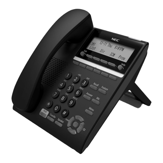
What’s in the box? NEC ITY-6D ITY-6D Base & Handset Figure 1: ITY-6D Base & Handset... -
Page 7: Guided Setup
Guided Setup Adjust the Angle of the Tilt Leg To adjust the tilt level of the phone: The height can be adjusted by moving the legs, which are attached to the bottom of the terminal. Second Level First Level Figure 2: Description of the position Turn the phone over (key side down). - Page 8 Adjust the legs to the desired height (The upper they are, the lower the phone becomes). First Level Second Level Figure 4: Adjust the legs Attach the Handset Please follow the diagram to attach the handset. Insert the coiled cord plug into the HANDSET connector on the back of the phone until it sounds a click.
- Page 9 Thread the LAN cable through the groove on the bottom of the tilt legs. Figure 6: Thread the LAN cable through the groove Configure a Headset To utilize a headset, it must be enabled that the headset mode on the phone: Press the “Menu”...
- Page 10 The phone will now pick the headset as the default communication method when placing and answering phone calls. To return the phone to non-headset mode, follow the steps in “Configure a Headset” and set Headset to Disabled. Connect a Computer (Optional) A computer can be connected to the network through the phone using a LAN cable if there are a limited number of available ports on the local area network.
- Page 11 Features NEC ITY-6D Figure 9: ITY-6D Features Description Reference Feature Feature Description Number • If missed call notification for the call indicator lamp is disabled (default), the lamp flashes for incoming and missed calls, and displays steady red for message waiting.
- Page 12 The LCD (Liquid Crystal Display) provides call status activity information plus date, time and softkey operation. This key can be used to exit from the Menu or Exit key Help mode and go back to the telephone main screen. The softkeys show the available features for the current activity.
-
Page 13: Basic Key Operations
BASIC KEY OPERATIONS This chapter describes basic keys on the phone such as cursor pad or key pad. Table 1: Description of the cursor pad and key pad User actions/Keys Digit key Select corresponding menu Item ◄ 4-way scroll BACK key Return to User Settings menu (Redial key) ►... - Page 14 Table 2: Menu list descriptions Menu Items Description 1 Personal Directory Opens the Personal Directory Invokes Call History. It shows information about 2 Call History Missed Calls, Placed Calls and Received Calls. Invokes User Settings, including headset options, 3 User Settings date/time options, LCD contrast settings and language options.
- Page 15 SOFTKEYS, EXIT AND HELP KEYS Softkeys The softkeys on the phones provide a set of functions on the LCD that adapts to the changing state of the phone. The softkeys, at the bottom of the LCD, display the names of available functions, names of user-assigned functions and names of functions assigned by a specific softkey pattern.
-
Page 16: Gigabit Ethernet Support
Exit and Help keys Press the Exit key to exit the Menu screens and return to the main screen. The Help key can be used to view information about the softkeys that are displayed on the phone. 1. Press the “Help” key. 2. - Page 17 Voicemail Box Setup RECORDING YOUR PERSONAL VOICEMAIL GREETING Press the “Voicemail” soft key. Enter the PIN provided to you by your Administrator, followed by # key. Select option 3 for personal options. Select option 1 to record your voicemail greeting. Follow the voice prompts to record and check your greeting.
-
Page 18: Commonly Used Features
Commonly Used Features PLACING OUTGOING CALLS When the phone is not in use: Pick up the handset or press the “Speaker” key. Dial an extension or telephone number Note: The Delete softkey can be used to delete the last digit (backspace). Press the Dial softkey to initiate the call, or wait a few seconds for the call to be automatically dialed. - Page 19 Note: If any settings are being changed on the phone or a Personal Directory or Speed Dial entry is being modified, the changes will be discarded once the Line Key is pressed. TRANSFERRING THE CURRENT CALL TO THE HEADSET While on a call using the handset, press the “Headset” softkey to transfer the call to the headset, then hang-up the handset.
-
Page 20: Call Waiting
Press the “Dial” softkey, or wait a few seconds for the call to be automatically transferred. The call is immediately transferred and the phone is disconnected. Attended Transfers: While on a call, press the “Transfer” line key. Dial an extension or telephone number. Press the “Dial”... - Page 21 Ringer volume (phone/headset): Press the Up/Down key on the Cursor pad while the phone is not in use. VOICEMAIL While the phone is not in use, press the “Voicemail” softkey. Enter the voicemail PIN followed by #. Press 1 to listen to new voicemail messages.
-
Page 22: Advanced Features
Advanced Features CALL PARK Placing Calls on Park: While on a call, press the Call Park line key (programmed previously via Control Panel) or dial *7. An announcement will sound which extension the call is parked. Retrieving Calls from Park: From any phone, dial the extension where the call was parked or select the Monitor Park Slot Line Key (programmed previously via Control Panel). - Page 23 Hang Up while conferencing: To hang up the established conference call, press the “EndCall” softkey. While the phone for the third party is still ringing, the other two parties will be connected in a blind transfer call. If the conference was ended by on hook the handset or pressing “Speaker”...
-
Page 24: Personal Directory
Note: Note: Different states have different laws about the notification that calls are being recorded. Administrators can choose whether to enable or disable a call recording announcement based on their state’s requirements. If enabled, “Your call is being recorded” plays when the phone starts recording. PAGING Paging Phones in a Group: o Dial the Page Group extension number or select the Paging line key... -
Page 25: Call History
To add a Personal Contacts entry: Press the “Directory” key. Press the “>>>” softkey Press the “Add” softkey. Use the keypad to enter the name and press Enter on the cursor pad or the “OK” softkey. Use the * key to switch between uppercase and lowercase keypad entry modes. - Page 26 Use the ↑Up and ↓Down softkeys or the Up and Down keys on the cursor pad to scroll through the call information. Press the “Exit” softkey to return to the Call History menu. After viewing the Missed Call History, the View Missed Calls message and missed calls icon are removed from the main LCD screen, and if enabled for missed call indication, the Call Indicator Lamp is cleared.
- Page 27 To Delete Call History for all Missed, Received or Placed Calls: Press the “Menu” key. Select 2 “Call History”. Select 4 “Delete”. Select either 1 Delete Missed Calls, 2 Delete Received Calls, or 3 Delete Placed Calls. The call information is deleted from the call history To Delete All Call History Information Press the “Menu”...
-
Page 28: Status Display Icons
Icon Display STATUS DISPLAY ICONS The LCD on the phone displays icons that provide notification for events, such as missed calls and voice mail. The icons appear in the topmost display line, known as the title bar. Table 3: Status Display Icons Feature Display by the Icon Feature Description... - Page 29 The number on the left shows which call is Call Count focused, and the number on the right shows the total number of calls. The number on the left shows the page currently displayed, and the number on the Page Count right shows the total number of pages in the current menu.
- Page 30 This icon indicates that the keypad generates Keypad in all only capital letters when entering data. uppercase entry Example: ABC D EFG mode To switch between keypad entry modes, press the * key on the telephone keypad. This icon indicates that the keypad generates Keypad in all only small letters when entering data.
- Page 31 Handset Call Volume Shows the volume level of the handset during a call. Speaker Call Volume Shows the volume level of the speaker during a call. MONITOR PRESENCE ICONS Table 5: Monitor Presence Icons for ITY-6D phones Programmable key Type Status Icon...
- Page 32 SECURE CALL ICONS A lock symbol appears in the registration icon when secure signaling is used, such as a TLS connection. Media Security Icon Signaling Media Registration Icons White Black Background Background Non-TLS None None SRTP None None SRTP...
-
Page 33: User Settings
Menu List USER SETTINGS Select this option to configure the user settings. These settings are updated automatically based on the Control Panel when connecting the network. The default values listed in the following table are the factory default setting. Table 6: User Settings Menu List Default Menu Item Description... - Page 34 Ringtone Table 7: Menu List - Ringtone Default Menu Item Description Value Internal Ringtone Select this option to specify the internal ringtone. Default External Ringtone Select this option to specify the external ringtone. Default Headset Table 8: Menu List - Headset Default Menu Item Description...
-
Page 35: Input Characters
Input Characters The following tables show the character sets (uppercase, lowercase) and numeric that are available on the phone. ALPHABETIC CHARACTERS When entering the name, it can enter uppercase and lowercase standard and European characters. The keypad is in upper case entry mode upon entering the screen. - Page 36 Uppercase Alphabetical Character Set Figure 12: Uppercase Alphabetical Character Set...
- Page 37 Lowercase Alphabetic Character Set Figure 13: Lowercase Alphabetical Character Set...
- Page 38 Numeric Character Set When in numeric character entry mode, the numbered keys on the phone can be used to enter numbers, and the # key to enter special characters. It can switch between character sets by pressing the key. The full numeric character set is only available when you are in a field that also allows alphabetic input.
- Page 39 Guided Option Setup Wall Mount the Phone The IP4WW-Wall Mount Unit is used to mount the DT820 terminals to the wall. This unit connects to the back of the terminal. Prepare the wall mounting Use the template in Figure 15: IP4WW-Wall Mount Unit Spacing Guide for required spacing before drilling.
- Page 40 Install two screws into wall. Leave about 0.12” (3mm) spacing between screw head and wall. Figure 16: Installing the Screws Adjusting the Hanger Hook Remove the hook from the unit. Figure 17: Removing the Hanger Hook Turn the hook with the tab toward the top. Slide the hook until it glides into position forming the hanger hook for the handset.
- Page 41 Figure 18: Sliding the Hanger Hook into Position Installing the IP4WW-Wall Mount Unit From the back of the terminal, move the handset cable to the cable groove shown (refer to Figure 19: Relocating the Handset Cable). Note: Before moving the leg to the folded position, the handset cable must be installed in the cable groove shown to prevent damage to cable.
- Page 42 Figure 20: Installing the IP4WW-Wall Mount Unit Pass the LAN cable through bottom of the IP4WW-Wall Mount Unit and plug into the LAN port. Figure 21: Installing the LAN Cable...
- Page 43 Wall Mounting the DT820 Multiline Terminal Using the screws previously installed, mount the phone on the wall. Figure 22: Mount the phone on the wall...
- Page 44 We are here to help. http://kb.univerge.blue/main/ © NEC Platforms, Ltd. 2021...
Need help?
Do you have a question about the ITY-6D and is the answer not in the manual?
Questions and answers