Rohm RKX-EVK-001 User Manual
Hide thumbs
Also See for RKX-EVK-001:
- User manual (56 pages) ,
- User manual (4 pages) ,
- User manual (34 pages)
Table of Contents
Advertisement
Quick Links
RKX-EVK-001 and ROHM EVK EVB
ROHM EVK HW User's Guide
The ROHM EVK is an easy-to-use platform that allows evaluation of ROHM products. The evaluation kit is based on the Infineon CY8CKIT-059
Prototyping Kit featuring an integrated SoC based on the ARM® Cortex®-M3 CPU with powerful analog and digital peripherals. The ROHM EVK
comes with a highly configurable RKX-A3-EVK-001 that provides an easy-to-use hardware interface between the MCU and the variety of Digital
ROHM devices in a plug-and-play fashion. Finally, the ROHM EVK GUI SW, a powerful Windows-based desktop application, provides an intuitive
Graphical User Interface capable of displaying and logging the real-time device data, and configuring the device functions through a graphical
register editor, to name a few.
This user guide describes the ROHM EVK HW. For the ROHM EVK SW, please refer to the ROHM EVK SW User's Guide.
Definitions
ROHM EVK
ROHM EVK HW
RKX-EVK-001
RKX-A3- EVK-001
ROHM EVK EVB
Accelerometer EVB
ADC EVB
ROHM EVK SW
ROHM EVK GUI SW
ROHM EVK FW
Acronyms
ADC
GUI
PSoC
© 2022 ROHM Co., Ltd.
Provides the full range of software, hardware and the firmware used for device evaluation purposes.
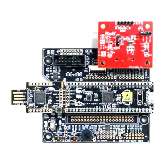
ROHM EVK EVB connected to RKX-EVK-001 board
RKX-A3-EVK-001 + CY8CKIT-059 Prototyping Kit
Adapter board specifically designed to easily interface with the ROHM EVK Evaluation Board and
development platforms
Accelerometer evaluation board or ADC evaluation board
Evaluation board with an accelerometer
Evaluation board with an ADC
Provides the full range of the software for device evaluation purposes consisting of ROHM EVK GUI
SW and RKX EVK FW
ROHM device evaluation software with a graphical user interface running on Windows OS
Proprietary firmware running on microcontroller-based host adapters
A/D Converter
Graphical User Interface
Programmable SoC (System on Chip)
1/23
User's Guide
No. 64UG116E Rev.002
Feb.2022
Advertisement
Table of Contents

Subscribe to Our Youtube Channel
Related Manuals for Rohm RKX-EVK-001


Summary of Contents for Rohm RKX-EVK-001
-
Page 1: Definitions
ROHM EVK HW User’s Guide The ROHM EVK is an easy-to-use platform that allows evaluation of ROHM products. The evaluation kit is based on the Infineon CY8CKIT-059 Prototyping Kit featuring an integrated SoC based on the ARM® Cortex®-M3 CPU with powerful analog and digital peripherals. The ROHM EVK comes with a highly configurable RKX-A3-EVK-001 that provides an easy-to-use hardware interface between the MCU and the variety of Digital ROHM devices in a plug-and-play fashion. -
Page 2: Table Of Contents
RKX-EVK-001 Communication Issues............................. 19 5.1.2 USB performance issues .................................. 22 “EVK Mismatch” – state with the ROHM EVK GUI SW ........................22 ODR accuracy and Timestamping ............................... 22 .NET installation related problem ................................. 22 Desktop shortcuts may not work properly ............................23 ©... -
Page 3: Rohm Evk Hw Overview
ROHM EVK HW Overview ROHM EVK HW Contents The RKX-EVK-001 sales package comes with the RKX-EVK-001, one micro-USB cable (3.3’), and one 14-position ribbon cable (1.5’) by default. (Figure 1) The RKX-EVK-001 is designed to work seamlessly with the Accelerometer EVB (e. g. KX132-1211-EVK-001) and ADC EVB (BU79100G-LA- EVK-001) that can be purchased separately. -
Page 4: Rkx-A3-Evk-001
1.3.1 RKX-A3-EVK-001 Detailed Diagram The RKX-A3-EVK-001 is designed to easily interface with ROHM products and numerous development platforms. By default, the board is populated to interface with the Infineon CY8CKIT-059 PSoC® prototyping platform and with ROHM standard evaluation boards featuring a 14-pin male header. -
Page 5: Input / Output Power Configuration
SW2 - 7-position rotary switch to configure VR1_OUT voltage: 19 J10 - ROHM Sensor Module 5-Pin Digital / 4-Pin Analog Header 1 = 3.3V, 2 = 3.0V, 3 = 2.8V, 4 = 2.5V, 5 = 1.8V, 6 = 1.7V, 7 = 3.6V TP3 - Test Point 3 for VDD_SENSOR voltage measurement. - Page 6 SW2, the LED2 light will be dim. If the orange LED (LED2) is completely OFF and the green led (LED1) is ON, please ensure the switch SW2 is not turned to an intermediate position and is at one of the 7 positions shown in Table 2. © 2022 ROHM Co., Ltd. No. 64UG116E Rev.002 6/23 Feb.2022...
- Page 7 The positive terminal of the external power supply can then be attached to the test point TP3 and negative terminal can be attached to any GND location on the RKX-A3-EVK-001. One such convenient location is a test point TP1 shown in Figure 7. Figure 7. External Voltage Source Recommended Connection © 2022 ROHM Co., Ltd. No. 64UG116E Rev.002 7/23...
-
Page 8: Vdd_Sensor Current Measurements
It is possible to bypass the onboard level shifters if needed. This can be accomplished from removing the zero-ohm resistors on A and B sides of the level shifter and connecting level shifter bypass resistors (R50-R57). Figure 9. Voltage Level Shifters for I/O Signals © 2022 ROHM Co., Ltd. No. 64UG116E Rev.002 8/23... -
Page 9: Interface With Evaluation Boards
Physical Interfacing with ROHM EVK EVB The RKX-A3-EVK-001 comes with pair of headers that provides an easy way to connect to the standard ROHM EVK EVB that come with a 14- pin male header. One header is a J5 14-pin male header, and another header is a J6 18-pin female header (Figure 10). -
Page 10: Interface With Host Platforms
Interface with host platforms The RKX-A3-EVK-001 is designed to provide an easy hardware interface between ROHM devices and numerous development platforms. Table 4 shows the list of host platforms that can be directly interfaced with the RKX-A3-EVK-001 via compatible headers. Note, that in order to interface with any given host platform, the proper hardware modifications may be required, including populating headers, and populating / removing certain zero-ohm resistors. -
Page 11: Infineon Cy8Ckit-059 Prototyping Kit
3.1.1 Overview As was previously described, the RKX-EVK-001 uses the Infineon CY8CKIT-059 Prototyping Kit as the target host adapter platform due to the numerous advantages it offers including high performance, mixture of onboard digital and analog peripherals, support for Full Speed USB 2.0 connectivity, easy to use IDE with free license, and the low cost. - Page 12 PSoC™ 3, PSoC™ 4 or PSoC™ 5LP device. The KitProg firmware is provided as a bootloader image that can be upgraded to develop custom applications for it.” © 2022 ROHM Co., Ltd. No. 64UG116E Rev.002 12/23...
-
Page 13: Firmware Pinout
SPI (MOSI/SDI) J14-23 P1.6 I2C (SDA) J15-10 P0.1 SPI (MISO/SDO) / ADDR J14-24 P1.7 SYNC/TRIG J14-4 P2.3 INT1 J14-13 P12.3 INT2 J14-5 P2.4 nRES J14-6 P2.5 R125 Z_OUT J15-19 P3.6 © 2022 ROHM Co., Ltd. No. 64UG116E Rev.002 13/23 Feb.2022... -
Page 14: About Rkx-A3-Evk-001
Board Size: 86.36 mm x 76.20 mm • Board Thickness: • Number of Layers: 4 • Material: FR-4 High Tg • Copper Thickness: 1oz (35μm) Figure 14. RKX-A3-EVK-001 Schematic Diagram © 2022 ROHM Co., Ltd. No. 64UG116E Rev.002 14/23 Feb.2022... - Page 15 User’s Guide © 2022 ROHM Co., Ltd. No. 64UG116E Rev.002 15/23 Feb.2022...
- Page 16 User’s Guide Figure 15. Schematic Diagram of RKX-A3-EVK-001 © 2022 ROHM Co., Ltd. No. 64UG116E Rev.002 16/23 Feb.2022...
-
Page 17: Bill Of Materials
U1, U2 VQFN (14) Voltage Level Translator SW1, SW3 SPDT Slide switch SP7T Switch Rotary SPDT Slide switch 14pin Connector 14pin Connector 24pin Connector 20pin Connector J14, J15 26pin Connector © 2022 ROHM Co., Ltd. No. 64UG116E Rev.002 17/23 Feb.2022... -
Page 18: Layout (Top View)
User’s Guide Layout (Top View) Figure 16. Layouts of RKX-A3-LA-EVK-001 © 2022 ROHM Co., Ltd. No. 64UG116E Rev.002 18/23 Feb.2022... -
Page 19: Troubleshooting And Known Issues
User’s Guide Troubleshooting and known issues In case of connection problems or an application crash, please check the error log file of the ROHM EVK GUI SW. The default path of this file is: ..\Documents\ROHM_EVK_v3\ROHM-EVK-GUI\errorlog.txt Communication Troubleshooting 5.1.1 RKX-EVK-001 Communication Issues The communication between the ROHM EVK GUI SW and RXK-EVK-001 may not work for several reasons. - Page 20 • If the blue LED1 (CY8CKIT-059) is blinking, the CY8CKIT-059 is not programmed with the ROHM EVK FW. Please program the latest ROHM EVK FW. See (3.1 Firmware Update Procedure in ROHM EVK SW User’s Guide) for details. • If the...
- Page 21 This error example issue is limited for RKX-EVK-001 connections. If the connection status as indicated in the status bar says “No data in stream”, the ROHM EVK GUI SW is not receiving any device data. To troubleshoot the issue, please check the following: This example case is valid for RKX-EVK-001 with an EVB.
-
Page 22: Usb Performance Issues
• The real-time ODR shown in the ROHM EVK GUI SW may show fluctuating and be off the nominal ODR value. If the value is within ~10% of the nominal value, the behavior is normal and can be due to a combination of factors such as fluctuation of the actual sensor ODR due to internal oscillator jitter, as well as the timestamping error mentioned above. -
Page 23: Desktop Shortcuts May Not Work Properly
Desktop shortcuts may not work properly • Sometimes after installation the desktop shortcuts will not work. To overcome this, please uninstall and reinstall the application again to a different destination directory. © 2022 ROHM Co., Ltd. No. 64UG116E Rev.002 23/23 Feb.2022... - Page 24 Products. ROHM does not grant you, explicitly or implicitly, any license to use or exercise intellectual property or other rights held by ROHM or any other parties. ROHM shall have no responsibility whatsoever for any dispute arising out of the use of such technical information.
Need help?
Do you have a question about the RKX-EVK-001 and is the answer not in the manual?
Questions and answers