Table of Contents
Advertisement
Quick Links
RKX-EVK-001 and ROHM EVK EVB
ROHM EVK SW User's Guide
The ROHM EVK is an easy-to-use platform that allows evaluation of ROHM products. The evaluation kit is based on the Infineon CY8CKIT-059
Prototyping Kit featuring an integrated SoC based on the ARM® Cortex®-M3 CPU with powerful analog and digital peripherals. The ROHM EVK
comes with a highly configurable RKX-A3-EVK-001 that provides an easy-to-use hardware interface between the MCU and the variety of Digital
ROHM devices in a plug-and-play fashion. For example, RKX-A3-EVK-001 is compatible with Arduino open-source hardware. Finally, the ROHM
EVK GUI SW, a powerful Windows-based desktop application, provides an intuitive Graphical User Interface capable of displaying and logging
the real-time device data, and configuring the device functions through a graphical register editor, to name a few.
This user guide describes the ROHM EVK SW. For the ROHM EVK HW, please refer to the ROHM EVK HW User's Guide.
Definitions
ROHM EVK
ROHM EVK SW
ROHM EVK GUI SW
ROHM EVK FW
ROHM EVK HW
RKX-EVK-001
RKX-A3-EVK-001
Accelerometer EVB
ADC EVB
ROHM EVK EVB
Acronyms
ADC
GUI
PSoC
© 2022 ROHM Co., Ltd.
Provides the full range of software, hardware and the firmware used for device evaluation purposes.
Provides the full range of the software for device evaluation purposes consisting of ROHM EVK GUI
SW and RKX EVK FW
ROHM device evaluation software with a graphical user interface running on Windows OS
Proprietary firmware running on microcontroller-based host adapters
ROHM EVK EVB connected to RKX-EVK-001 board
RKX-A3-EVK-001 + CY8CKIT-059 Prototyping Kit
Adapter board specifically designed to easily interface with the ROHM EVK Evaluation Board and
development platforms
Evaluation board with an accelerometer
Evaluation board with an ADC
Accelerometer evaluation board or ADC evaluation board
A/D Converter
Graphical User Interface
Programmable SoC (System on Chip)
1/55
User's Guide
No. 64UG118E Rev.005
Jan.2023
Advertisement
Table of Contents

Related Manuals for Rohm RKX-A3-EVK-001


Summary of Contents for Rohm RKX-A3-EVK-001
-
Page 1: Definitions
ROHM EVK SW User’s Guide The ROHM EVK is an easy-to-use platform that allows evaluation of ROHM products. The evaluation kit is based on the Infineon CY8CKIT-059 Prototyping Kit featuring an integrated SoC based on the ARM® Cortex®-M3 CPU with powerful analog and digital peripherals. The ROHM EVK comes with a highly configurable RKX-A3-EVK-001 that provides an easy-to-use hardware interface between the MCU and the variety of Digital ROHM devices in a plug-and-play fashion. -
Page 2: Table Of Contents
ROHM EVK SW Overview ............................................ 4 Introduction ......................................4 Setup ........................................4 1.2.1 Installation ......................................4 1.2.2 Start with ROHM EVK GUI SW ................................4 1.2.2.1 When you connect RKX-EVK-001 to a computer........................4 1.2.2.2 Connection status indicator .................................7 1.2.3 Some example cases of connecting the RKX-EVK-001 ........................8 1.2.3.1... - Page 3 4.1.1.1 “Status: EVK Disconnected” in ROHM EVK GUI SW Status Bar ..................50 4.1.1.2 “Status: No data in stream” in ROHM EVK GUI SW Status Bar .................... 51 4.1.2 USB performance issues .................................. 52 “EVK Mismatch” – state with the ROHM EVK GUI SW ........................52 ODR accuracy and Timestamping ...............................
-
Page 4: Rohm Evk Sw Overview
ROHM EVK GUI SW is compatible with Windows OS versions 7, 8 and 10. Minimum recommended display resolution is 1920 x 1080. Setup 1.2.1 Installation If ROHM EVK Software has not been installed already, it can be installed by downloading the latest installer file from the ROHM Semiconductor website: https://www.rohm.com/support/accelerometer-evk-support Before running the ROHM EVK GUI SW, the necessary USB serial drivers must be installed (if Windows does not install these drivers automatically). - Page 5 The application is also able to be launched from the Start–menu of Windows 10 (Figure 2). Figure 2. ROHM application folder in the Start-menu Select a suitable board from the dropdown menu (Figure 3) of the Connection status indicator or from the Board – menu (Figure 4) Figure 3.
- Page 6 In this example, RKX-EVK-001 + ADC EVB are shown. Figure 5. Board Information Tab After the verification is done, connect your device to the computer with a micro-USB cable (Figure 6). The ROHM EVK GUI SW connection status indicator will change to yellow, “EVK Connected” state (Figure 5).
-
Page 7: Connection Status Indicator
When ROHM-EVK-001 is connected to the computer with a micro-USB, the status will change to “EVK Connected”. After the “Confirm board” button is pressed, the status of the ROHM EVK GUI SW will change to “EVK Ready”. Figure 8, ROHM EVK GUI SW Connection Status ©... -
Page 8: Some Example Cases Of Connecting The Rkx-Evk-001
Connect the RKX-EVK-001 to the PC with the provided micro-USB cable (Figure 6). • Launch the ROHM EVK GUI SW application. • If a Configuration update pop-up window appears, click Yes to download the latest configurations from the server (Figure 9). -
Page 9: An Example For The Adc Evaluation
If the “Please enable streaming to activate Plotter movement!” – Pop-up window appears on the screen, enable data streaming with the “Streaming” button. The plotter should now display real time output for ADC (Figure 11). Figure 11. Plotter view with measurements of BU79100G-LA displayed © 2022 ROHM Co., Ltd. No. 64UG118E Rev.005 9/55 Jan.2023... -
Page 10: User Interface - Menu Bar
User’s Guide User Interface – Menu bar Most of the functionality of the ROHM EVK GUI SW is accessible from the menu bar. Short description of the menu items is available by hovering the mouse pointer on the menu items. -
Page 11: Automatic Log Files
1.3.3 Connection – Menu The ROHM EVK GUI SW connects to the RKX-EVK-001 via a USB COM port. The Bluetooth connection (Windows BLE) is reserved for other host platforms supported by the ROHM EVK. The ROHM EVK GUI SW uses USB COM connection by default. When auto-connect is enabled, the USB connection is established automatically when the RKX-EVK-001 is connected. -
Page 12: Load Register Configuration From File
Selecting this menu allows the user to save all the current register values from the register editor to a file (Figure 17) Figure 17. Partial Snapshot of the KX132-1211 Register Dump NOTE: The default location to save the Register Dump file is: \Documents\ROHM_EVK_v3\ROHM-EVK-GUI\log_files © 2022 ROHM Co., Ltd. No. 64UG118E Rev.005 12/55 Jan.2023... -
Page 13: Open Register Map Definition
Selecting this menu allows the verification of the written register values by reading the values from the IC after write. 1.3.5 Settings – Menu The settings menu contains various connectivity and functionality settings. Figure 19. Settings Menu © 2022 ROHM Co., Ltd. No. 64UG118E Rev.005 13/55 Jan.2023... -
Page 14: Auto Connect Usb
User’s Guide 1.3.5.1 Auto Connect USB When “Auto connect” is enabled, every time when ROHM EVK GUI SW is started, it will automatically select the USB COM port for the connected device and connect to it. 1.3.5.2 Auto config and registers download When “Auto config download”... -
Page 15: Board - Menu
The Board menu lists either all supported board configurations for all supported Host Adapters (Figure 23) or only the relevant ones (Figure 22) that are supported by the Host Adapter currently plugged in, e.g., CY8CKIT-059 / RKX-A3-EVK-001 / that comes with the ROHM EVK package by default. -
Page 16: View - Menu
For ADC, the available board configuration is limited to the” BU79100G-LA-EVK-001”. 1.3.8 View – Menu The View menu item provides different features that can be shown or hidden in the ROHM EVK GUI SW. Figure 24. View Menu For sensor evaluation (e.g., KX132-1211), if “wake-up & Back-to-Sleep Detection streaming” is selected (Figure 20) the “Show wake up pop window”... -
Page 17: Digital Output In Sub Channel View
NOTE: When you have a very high ODR (12.8 kHz or 25.6 kHz), the digital output can slow down the performance. (1.6.3 ODR has not reached the target value pop-up window) Figure 26. Plotter view with Sub Channel View and Digital Output Enabled © 2022 ROHM Co., Ltd. No. 64UG118E Rev.005 17/55... - Page 18 50Hz ±2g high performance of the KX132-1211, in order to monitor the accelerometer’s Z axis only, press once on AccX and AccY to disable these channels. The only remaining channel would be AccZ as shown in (Figure 28). Figure 28. Plotter view with only AccZ sub-channel activated © 2022 ROHM Co., Ltd. No. 64UG118E Rev.005 18/55...
-
Page 19: Events View Panel
Reference line position is also shown in the Status bar (lower right corner of the window). To achieve a higher resolution / granularity when setting the reference line position, use the mouse scroll wheel to zoom into and out of the plotter window. Figure 30. Plotter view with reference line enabled © 2022 ROHM Co., Ltd. No. 64UG118E Rev.005 19/55... -
Page 20: Show All Board Configurations
Selecting “Release notes” opens the release notes-text file, where details of the version release are explained. 1.3.9.3 About ROHM EVK The “About ROHM EVK GUI SW” help menu shows the current ROHM EVK GUI SW’s version information. It also shows the link where the latest version can be downloaded from (Figure 32). -
Page 21: About Host Adapter Board
Figure 32. About ROHM EVK GUI SW 1.3.9.4 About Host Adapter Board The “About Host Adapter Board” help menu shows the current connected ROHM EVK HW and ROHM EVK FW information. (Figure 33). Figure 33. About Host Adapter Board Information menu for the CY8CKIT-059 Prototyping Kit ©... -
Page 22: User Interface - Tabs
User’s Guide User Interface - Tabs The functionalities of the ROHM EVK GUI SW are divided between separate tabs and all tabs are dockable. 1.4.1 Plotter – Tab The Plotter in (Figure 10 and Figure 11) shows device data from the current stream. The Plotter tool bar has its own Streaming and Raw data buttons to enable quick changing between the two (Figure 34). -
Page 23: Raw Data
In order to use Auto scaling after zooming, the “Auto scaling” - button must be activated again. 1.4.1.3 Moving The position of the Data axis (y-axis) can be moved up and down using the right mouse button. © 2022 ROHM Co., Ltd. No. 64UG118E Rev.005 23/55... -
Page 24: Frequency Analysis
NOTE: The x-axis range for the plot starts from 0 Hz and ends in ODR/2 Hz. It is automatically adjusted if the ODR is modified. Figure 38. Plotter view of KX132-1211 with FFT functionality Figure 39. ADC plotter view with FFT functionality © 2022 ROHM Co., Ltd. No. 64UG118E Rev.005 24/55... -
Page 25: Advanced Data Path (Adp)
Also, the Wake-up pop-up window is enabled (1.6.4 Wake up pop-up window). The pop-up window will appear when a wake-up event is active, e.g., when a signal within band-pass frequency range is present (Figure 42). © 2022 ROHM Co., Ltd. No. 64UG118E Rev.005 25/55 Jan.2023... - Page 26 If there is a need to change the threshold values, then the proper threshold values can be seen from the plotter view and then written to the sensor using the register editor see (1.4.3.4Stream modify mode) for details. Figure 42. The plotter view with ADP & WUF data stream © 2022 ROHM Co., Ltd. No. 64UG118E Rev.005 26/55...
-
Page 27: Angle Calibration - Tab
The user can start a new calibration by clicking the start button and by executing following steps while streaming is active. NOTE: If ROHM EVK GUI SW detects that calibration has been done on the same calibration position twice in a row, the Calibration Error window will appear, and the user will be required to restart the calibration procedure from the 1 calibration procedure (Figure 44). - Page 28 Click Next and hold the device still until the diagram changes to the 2 position (Figure 46) • The last current value for position 1 is now stored and shown in the 2 table. Figure 46. Angle Calibration. Position – 2 © 2022 ROHM Co., Ltd. No. 64UG118E Rev.005 28/55 Jan.2023...
- Page 29 The Inclinometer calibrated status will appear in the right corner of the status bar (Figure 49), and a small desktop notification message will appear for a few seconds to indicate that the calibration procedure is done (Figure 50). © 2022 ROHM Co., Ltd. No. 64UG118E Rev.005 29/55...
- Page 30 At this point, if the user is satisfied with the calibration parameters, they can be saved to an individual .json file that can be loaded next time the ROHM EVK GUI SW restarts. These calibration parameters will now be used for angle calculations.
-
Page 31: Registers - Tab
All the devices of the selected board, which have eligible registers can be selected from the “Device name” pull down menu. Figure 52. ROHM EVK GUI SW register editor tab NOTE: When the device register is selected from the pull-down menu, the name of the tab will change to one of the following: •... - Page 32 For example, to set the WUFTH value to 950 (0x03B6), write 950 to the WUFTH register 0x49, and the register WUFTH (0x49) will store the value 0xB6, while the register BTSWUFTH (0x4A) will store the value 0x03. © 2022 ROHM Co., Ltd. No. 64UG118E Rev.005 32/55 Jan.2023...
-
Page 33: Register Sets
Figure 58. Select set Drop Down Menu The register sets are a very useful feature of the ROHM EVK GUI SW as it allows the user to visually see only the registers of interest grouped together. Consider the Data Stream register set shown in (Figure 59). From this set, it is possible to select all the basic configurations of the accelerometer such standby/run mode, power mode, ODR, full scale range, and set some basic interrupt. - Page 34 <device name>_<set name>_set.txt For example, the Data Stream for KX132-1211 sensor is called: KX132-1211_Data Stream_set.txt Register Set File Structure Convention: The register set definition follows the following scheme: <Set Name>:Reg1,Reg2,Reg3 © 2022 ROHM Co., Ltd. No. 64UG118E Rev.005 34/55 Jan.2023...
-
Page 35: Register Polling Function
NOTE: The ROHM EVK GUI SW loads all the register sets on startup. If changes were made to the content of the register set files or new register set files were created, the changes will be visible the next time the program is loaded. -
Page 36: Stream Modify Mode
NOTE: When switching to the Plotter view, do not press the Streaming button again. When the Streaming button is disabled and enabled again, the default registers values as set in the stream configuration will be written to the device! © 2022 ROHM Co., Ltd. No. 64UG118E Rev.005 36/55 Jan.2023... -
Page 37: User Interface - Status Bar
Bluetooth communication is not supported by the RKX-EVK-001. NOTE: It is normal to see a slight variation in the ODR value. Data is received at varying intervals and the ODR is calculated when ROHM EVK GUI SW receives the data from the used connection layer. -
Page 38: User Interface - Pop-Up Windows
Figure 67. ODR information window The ODR warning pop-up window (Figure 67) appears anytime when the real time Output Data Rate (ODR) as measured by the ROHM EVK GUI SW is significantly different from the nominal ODR set in the Stream (Figure 68). This can happen, for example, when the selected ODR is greater than 3200Hz and the interface protocol is I2C and not SPI. -
Page 39: Wake Up Pop-Up Window
The Wake-Up Interrupt pop-up window that is displayed can be replaced with any custom image instead of the original file. The new image file must be called wakeup.png, have an approximate size of 380 x 190 pixels, and be placed in the ROHM EVK GUI SW Resource folder: ..\Documents\ROHM_EVK_v3\ROHM-EVK-GUI\Resources... -
Page 40: Shortcuts
User’s Guide Shortcuts The ROHM EVK GUI SW has many keyboard shortcuts: CTRL + L Enable/disable logging CTRL + S Enable/disable streaming Reset used connection and data streaming (disconnect and connect when having connection problem). Re- CTRL + R enable the Streaming when connection is established. -
Page 41: Usb Driver
User’s Guide USB Driver Before connecting the RKX-EVK-001 to a computer, it is highly recommended to install the ROHM EVK GUI SW first by using the installer file available for download on the ROHM Semiconductor website: https://www.rohm.com/support/accelerometer-evk-support If the ROHM EVK software installer is used, a separate USB driver installation for the Infineon CY8CKIT-059 Prototyping Kit is not required. Also, the Windows 10 operating system should automatically use the correct USB driver. - Page 42 Right-click the “Evaluation Kit (Infineon)” item, and choose “Update Driver Software …” A new window should open. Select “Browse my computer for driver software” (Figure 73). Figure 73. Update Driver Software - 1 © 2022 ROHM Co., Ltd. No. 64UG118E Rev.005 42/55...
- Page 43 Select “Let me pick from a list of device drivers on my computer”: (Figure 74). Figure 74. Update Driver Software – 2 Choose “Next” (the selection in the list does not matter) (Figure 75). Figure 75. Update Driver Software - 3 © 2022 ROHM Co., Ltd. No. 64UG118E Rev.005 43/55 Jan.2023...
- Page 44 The installer should install required files. If this kind of a pop-up window (Figure 77) appears, please proceed forward by selecting “OK”. You will be returned to an older pop-up window where you should select “Next” (Figure 78). Figure 77. Update Driver Software - 5 © 2022 ROHM Co., Ltd. No. 64UG118E Rev.005 44/55...
- Page 45 Windows will prompt you to install the driver, please select “Install” (Figure 79). Figure 79. Update Driver Software – 7 10. Finally, please wait until the driver installation is complete. © 2022 ROHM Co., Ltd. No. 64UG118E Rev.005 45/55 Jan.2023...
-
Page 46: Firmware
When the Infineon CY8CKIT-059 Prototyping Kit is supplied as part of the RKX-EVK-001, it will come pre-loaded with the ROHM EVK Firmware to interface with ROHM EVK GUI SW. To flash the latest ROHM EVK Firmware to the CY8CKIT-059 Prototyping Kit please follow the procedure outlined in (3.1 Firmware Update ). - Page 47 (File>File Load) or by pressing the F4 key (Figure 81). Next, flash the firmware on the CY8CKIT-059 Prototyping Kit by pressing the Down Arrow button (Figure 81, number 2) or through the © 2022 ROHM Co., Ltd. No. 64UG118E Rev.005 47/55 Jan.2023...
-
Page 48: Firmware Update For Arduino Uno R3
Download the avrdude zip package (Windows) from the avrdude official website. http//download.savannah.gnu.org/releases/avrdude/avrdude-6.4-mingw32.zip Following the installation of the ROHM EVK software, locate the Arduino folder from the computer in the following location: ..\Documents\ROHM_EVK_v3\ROHM-EVK-Firmware\Arduino and verify the presence of a ROHM EVK Firmware file with the extension ”.hex” and the arduino_flash.bat file. - Page 49 User’s Guide Figure 84, Firmware update for Arduino UNO R3 © 2022 ROHM Co., Ltd. No. 64UG118E Rev.005 49/55 Jan.2023...
-
Page 50: Troubleshooting And Known Issues
User’s Guide Troubleshooting and known issues In case of connection problems or an application crash, please check the error log file of the ROHM EVK GUI SW. The default path of this file is: ..\Documents\ROHM_EVK_v3\ROHM-EVK-GUI\errorlog.txt Communication Troubleshooting 4.1.1 RKX-EVK-001 Communication Issues The communication between the ROHM EVK GUI SW and RXK-EVK-001 may not work for several reasons. -
Page 51: Status: No Data In Stream" In Rohm Evk Gui Sw Status Bar
This error example issue is limited for RKX-EVK-001 connections. If the connection status as indicated in the status bar says “No data in stream”, the ROHM EVK GUI SW is not receiving any device data. To troubleshoot the issue, please check the following: This example case is valid for RKX-EVK-001 with an EVB. -
Page 52: Usb Performance Issues
NOTE: The ROHM EVK GUI SW does not check the value of the WHO-AM-I register. Thus, while the stream for KX132-1211 would work for KX134-1211 and vice versa (although SI values in Raw Data setting will be incorrect), neither of those streams would work if KXTJ3 sensor is connected and vice-versa. -
Page 53: Odr Accuracy And Timestamping
• The real-time ODR shown in the ROHM EVK GUI SW may show fluctuating and be off the nominal ODR value. If the value is within ~10% of the nominal value, the behavior is normal and can be due to a combination of factors such as fluctuation of the actual sensor ODR due to internal oscillator jitter, as well as the timestamping error mentioned above. -
Page 54: Appendix
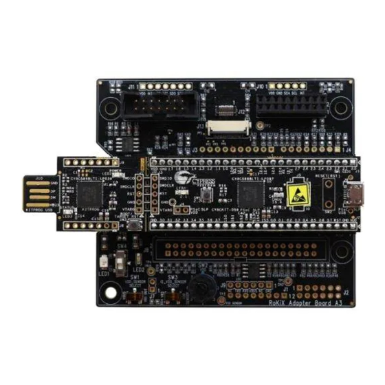
User’s Guide Appendix RKX-A3-EVK-001 Detailed Diagram For detailed information of the hardware, please refer to the ROHM EVK HW User's Guide. Figure 88. RKX-A3-EVK-001 Main Features Table 2. RKX-A3-EVK-001 Main Features TP4 - Test Point 4 for VBUS (Host) input voltage measurement 12... -
Page 55: Interface With Rohm Evk Evb
User’s Guide Interface with ROHM EVK EVB Figure 89. Interface with ROHM EVK EVB © 2022 ROHM Co., Ltd. No. 64UG118E Rev.005 55/55 Jan.2023... - Page 56 Products. ROHM does not grant you, explicitly or implicitly, any license to use or exercise intellectual property or other rights held by ROHM or any other parties. ROHM shall have no responsibility whatsoever for any dispute arising out of the use of such technical information.
Need help?
Do you have a question about the RKX-A3-EVK-001 and is the answer not in the manual?
Questions and answers