
Subscribe to Our Youtube Channel
Related Manuals for Rohm Lapis EASE1000 V2


Summary of Contents for Rohm Lapis EASE1000 V2
- Page 1 FEXTEASE1000V2-03 EASE1000 V2 User's Manual Edition Issue Date: Mar. 23, 2020 LAPIS Semiconductor Co., Ltd.
- Page 2 11) Please use the Products in accordance with any applicable environmental laws and regulations, such as the RoHS Directive. For more details, including RoHS compatibility, please contact a ROHM sales office. LAPIS Semiconductor shall have no responsibility for any damages or losses resulting non-compliance with any applicable laws or regulations.
-
Page 3: Table Of Contents
EASE1000 V2 User’s Manual Table of Contents CHAPTER 1 PREFACE ........................4 For Safe and Correct Operation ............................5 Precautions ..................................6 Description of Term ................................8 CHAPTER 2 GENERAL DESCRIPTION ..................9 2. General Description ..............................10 2.1 Product Overview ..............................10 2.2 EASE1000 V2 Components .......................... - Page 4 EASE1000 V2 User’s Manual REVISION HISTORY ........................31...
-
Page 5: Chapter 1 Preface
EASE1000 V2 User’s Manual Chapter 1 PREFACE... -
Page 6: For Safe And Correct Operation
EASE1000 V2 User’s Manual For Safe and Correct Operation This user's manual uses various terms and pictorial indications for you to use this product safely and correctly and to prevent harm to you and others and property damages. Their meanings and displays are as follows: Meaning of term Incorrect handling in defiance of this display may cause death or serious injury. -
Page 7: Precautions
EASE1000 V2 User’s Manual Precautions Be sure to read this page before using this product. Warning ● Do not use the product at a voltage other than specified one. It might cause fire, electric shock or failure. ● Do not remodeling the product. It might cause fire, electric shock or failure. - Page 8 EASE1000 V2 User’s Manual Be sure to read this page before using this product. Note ● Do not apply a voltage exceeding the 5.5V to the VTref pin of the EASE1000 V2 Interface cable. It might cause fire, electric shock or failure. ●...
-
Page 9: Description Of Term
EASE1000 V2 User’s Manual Description of Term The following shows the terms used in this user's manual and their descriptions. Term Description EASE1000 V2 It is an on-chip emulator for microcontroller of Lapis Semiconductor. It has a function as a writer (hereinafter referred to as flash writer) to a LSI with built-in flash memory, as well as the on-chip emulator function. -
Page 10: Chapter 2 General Description
EASE1000 V2 User’s Manual Chapter 2 General Description... -
Page 11: General Description
EASE1000 V2 User’s Manual 2. General Description 2.1 Product Overview EASE1000 V2 is an on-chip emulator for Microcontroller (hereinafter referred to as target LSI) of Lapis Semiconductor. In combination with the DTU8 debugger, it provides the on-chip debug function. Having the flash writer function as well, EASE1000 V2 can be used as a flash writer in combination with the MWU16 flash multi writer host program. -
Page 12: Ease1000 V2 Components
EASE1000 V2 User’s Manual 2.2 EASE1000 V2 Components The following shows the EASE1000 V2 components. Hardware EASE1000 V2 This is the main component of EASE1000 V2 on-chip emulator. Manuals Manual that describes the EASE1000 V2 on-chip emulator EASE1000 V2 (this manual) User’s manual Accessories Cable used to connect the EASE1000 V2 on-chip emulator to a... -
Page 13: Appearance
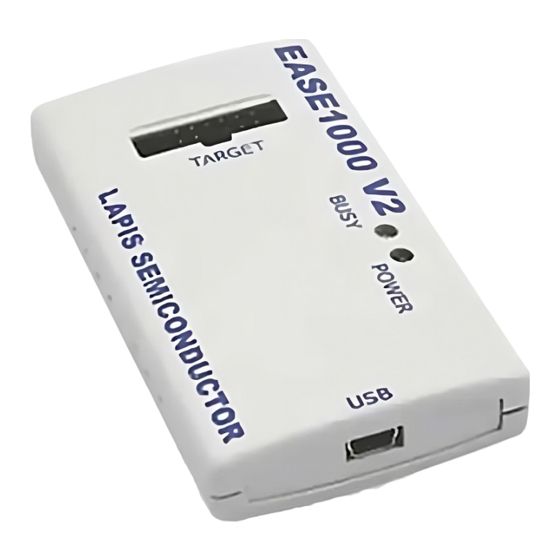
EASE1000 V2 User’s Manual 2.3 Appearance The following shows the appearance diagram of EASE1000 V2 and description of each part. In this description, a component surrounded by brackets is the name printed on the case. BUSY indicator POWER indicator (BUSY) (POWER) Target interface USB connector... -
Page 14: Terms Of Use
EASE1000 V2 User’s Manual 2.4 Terms of Use EASE1000 V2 should be used in an environment which meets the following conditions. Terms of use for EASE1000 V2 Parameter Description Power supply USB VBUS output (5 V, 500 mA) on the host PC Usage environment Temperature: 5 to 40 °C Relative humidity: 30 to 80% (no condensation) -
Page 15: Target System Requirements
EASE1000 V2 User’s Manual 2.5 Target System Requirements The target system connected with EASE1000 V2 must meet the following requirements. Target System requirements Item Description Interface connector Must support the EASE1000 V2 interface cable Must have a 14-pin 2.54 mm pitch connector (Compatible connector: HIF3FC-14PA-2.54DSA) Target LSI 1.6 to 5.5V (Note 1) - Page 16 EASE1000 V2 User’s Manual 2.5.1 Target System Board Layout The following shows a recommended board layout of the EASE1000 V2 interface connector in the target system. Target system Porality slot for EASE1000 V2 interface cable EASE1000 V2 Figure 2-4 EASE1000 V2 Interface Connector Recommended Board Layout Also, design the pin assignment of the EASE1000 V2 interface connector according to the following table.
- Page 17 EASE1000 V2 User’s Manual 2.5.2 Target System Circuit Configuration The circuit configuration to connect a target LSI with EASE1000 V2 is different depending on the specifications of the target LSI. Use an appropriate configuration according to the LSI user's manual. This section describes some notes when connect a target LSI with EASE1000 V2.
- Page 18 EASE1000 V2 User’s Manual 2.5.3 Supplying Target LSI V 2.5.3.1 Supplying Target LSI V from EASE1000 V2 EASE1000 V2 has the pin (3.3VOUT) to output +3.3 V/100 mA (max) as a target LSI operation power supply. When this power supply is used, the flash writer, on-chip debug emulator’s application program download and software breakpoint functions are available even when the power supply voltage of the target system is set to a value outside the flash memory operation voltage range of the target LSI.
- Page 19 EASE1000 V2 User’s Manual 2.5.4 Notes of Target System Board Layout The following shows the notes of target system board layout - The length of a cable connecting EASE1000 V2 with the target system (EASE1000 V2 interface cable) is approximately 15 cm. Locate the EASE1000 V2 interface connector at the end of PCB if possible in order to make the cable between the EASE1000 V2 interface connector and target LSI as short as possible.
-
Page 20: Chapter 3 Start
EASE1000 V2 User’s Manual Chapter 3 Start... -
Page 21: Start
EASE1000 V2 User’s Manual 3 START 3.1 Starting EASE1000 V2 This section describes how to start EASE1000 V2. For the following software running on the host PC, see the appropriate user's manual. - DTU8 User's Manual - MWU16 Flash Multi Writer Host Program User's Manual 3.1.1 Starting Procedure Start EASE1000 V2 according to the following procedure. - Page 22 EASE1000 V2 User’s Manual 3.1.2 Removal Procedure (1) Close the software on the host PC. (2) Turn off the target system. (3) Disconnect the USB cable from EASE1000 V2. (4) Disconnect the EASE1000 V2 interface cable between EASE1000 V2 and the target system. Be sure to disconnect according to the disconnecting procedure.
-
Page 23: Chapter 4 Functions
EASE1000 V2 User’s Manual Chapter 4 FUNCTIONS... -
Page 24: Functions
EASE1000 V2 User’s Manual 4 Functions 4.1 On-chip debug function Connecting EASE1000 V2 with a target LSI and using the DTU8 debugger provides the on-chip debug function. ・ Application program download/display/change ・ CPU status (register, Flash memory/Data memory, SFR) display/change ・... - Page 25 EASE1000 V2 User’s Manual The following describes the above EASE1000 V2 states. Table 4-2 State explanation of EASE1000 V2 Idle state Indicates the command reception waiting state from the software on the host PC to EASE1000 V2. Emulating Indicates that EASE1000 V2 is emulation state. Writing flash memory Indicates that flash memory writing to the target LSI is in progress.
-
Page 26: Chapter 5 Notes On Use Of Ease1000 V2
EASE1000 V2 User’s Manual Chapter 5 Notes on Use of EASE1000 V2... -
Page 27: Notes On Use Of Ease1000 V2
EASE1000 V2 User’s Manual 5 Notes on Use of EASE1000 V2 5.1 Notes on Debug (1) About the execution cycle at the wait mode. On wait mode, STEP execution may differ from the execution cycle of Go- execution. The final check of an application program should use Go-execution. (2) About the RAM Match Break ・The timing of RAM Match Break is after executing a maximum of 3 instruction from the instruction which read/write access of RAM. -
Page 28: About Flash Writing
EASE1000 V2 User’s Manual 5.4 About Flash Writing Confirm before using EASE1000 V2 as a flash writer that the target LSI power supply voltage (V ) is within the operating conditions of the flash memory. When connecting the ML610QXXX or ML620QXXX as target LSI, please confirm that the voltage of flash programming power supply (Vpp) and internal logic power supply (VDDL) are also within the operating conditions of the flash memory. -
Page 29: Chapter 6 Appendices
EASE1000 V2 User’s Manual Chapter 6 Appendices... -
Page 30: Appendices
EASE1000 V2 User’s Manual 6. Appendices 6.1 Form information 6.1.1 EASE1000 V2 Item Description Outside dimension 50 (W)×17(H)×90(D)[mm] Weight 6.1.2 EASE1000 V2 Interface cable Item Description Cable length 150[mm] Connector form 2.54mm pitch 14 pins Two-row socket 6.1.3 USB cable Item Description Cable length... -
Page 31: Update Of Firmware
EASE1000 V2 User’s Manual 6.3 Update of Firmware Please confirm the latest version of firmware at a LAPIS support site. Please refer to the “Firmware Update function” section of “DTU8 Debugger User’s Manual” for an update procedure. - Page 32 EASE1000 V2 User’s Manual Revision History...
- Page 33 EASE1000 V2 User’s Manual Revision History Page Document No. Date Description Previous Current Edition Edition FEXTEASE1000V2-01 July 20, 2018 First Edition Described that check the manual of LSI about connection method. Described that check the FEXTEASE1000V2-02 Feb. 19, 2019 manual of LSI about connection method.
Need help?
Do you have a question about the Lapis EASE1000 V2 and is the answer not in the manual?
Questions and answers