Download Print this page
South ET-02 Service Manual

South ET-02 Service Manual

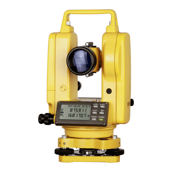
Electronic theodolite

Advertisement

Quick Links

2009
 
ELECTRONIC
THEODOLITE
SERVICE MANUAL
 
SOUTH SURVEYING & MAPPING INSTRUMENT
CO., LTD.


SOUTH
2009‐6‐1


Advertisement

loading
Need help?

Need help?

Do you have a question about the ET-02 and is the answer not in the manual?

Questions and answers

Summary of Contents for South ET-02

  • Page 1 2009   ELECTRONIC THEODOLITE SERVICE MANUAL   SOUTH SURVEYING & MAPPING INSTRUMENT CO., LTD.       SOUTH 2009‐6‐1                    ...
  • Page 2 2  SOUTH SURVEY & MAPPING INSTRUMENT CO., LTD.    The structure of Electronic Theodolite The ET of this series includes telescope, vertical encoder disk, horizontal encoder disk, electronic reading system, plate level, vertical axis, horizontal axis, horizontal clamp and tangent screw, vertical clamp and tangent screw, optical plummet, base and so on.
  • Page 3 3  SOUTH SURVEY & MAPPING INSTRUMENT CO., LTD.    G. Horizontal Clamp and Tangent Unit Its case is just the same as that of vertical clamp and tangent unit. Pass it over here. H. Level Unit a. Plate level The plate level with protective glass is installed on the alidade bracket and is vertical to adjustment vertical axis unit.
  • Page 4 This chapter introduce the normal entire disassembly process of absolute encoder type electronic theodolite ET-02/ET-05 and the process comply the following steps. The assembly process is the same as the disassembly if there is not any special note. Please refer to the related information in this chapter if some parts need to be maintained or replaced.
  • Page 5 5  SOUTH SURVEY & MAPPING INSTRUMENT CO., LTD.    3. LCD plate Remove the 4 screws fixing the display plate and then open the LCD plate lightly. Take out the LCD and keep it carefully. 4 Right cover Refer to step 3, take off the LCD plate on the left of right cover.
  • Page 6 6  SOUTH SURVEY & MAPPING INSTRUMENT CO., LTD.    Step 5: Vertical absolute encoder disk unit (left horizontal axis for short) Refer to step 1 and 2, unload the left cover and angle main board. Refer to the picture, remove the 4 dust-proof setscrews on A points and 4 setscrews fixing CCD laser tube on B points.
  • Page 7 7  SOUTH SURVEY & MAPPING INSTRUMENT CO., LTD.    assembly notice: the left horizontal axis should be installed according the following principle. If replacing CCD unit is needed, install two vertical CCD units first. then find out the triangle start mark on the encoder disk edge(circled in the picture). This mark point at the position of the start code of the encoder.
  • Page 8 8  SOUTH SURVEY & MAPPING INSTRUMENT CO., LTD.    Step 7: Left horizontal axis sheath (vertical CCD unit bracket) refer to step 1, 2, 5 and 6, remove left cover, angle main board, vertical absolute encoder disk and vertical CCD unit, then invert the disk unit, there is a copper horizontal axis, use a round clamp to remove the fix cover.
  • Page 9 9  SOUTH SURVEY & MAPPING INSTRUMENT CO., LTD.    Step 11: Horizontal absolute encoder disk unit and vertical axis unit(Lower base unit for short) According to the direction of red arrow shown in the picture, loosen the base locker to separate the base. Invert the whole lower base unit and remove the 3 lower base cover-protection screws, then take off the lower base cover.
  • Page 10 10  SOUTH SURVEY & MAPPING INSTRUMENT CO., LTD.    Hold the main body tightly by two hands toward the red arrow direction show in the picture. Tale care avoid the horizontal clamp ring and draw two units of connecting wire of the horizontal CCD. Then the upper body separated form the lower base unit.
  • Page 11 11  SOUTH SURVEY & MAPPING INSTRUMENT CO., LTD.    Keep the bottom of the lower base upward. Uplift the lower base gently along the direction of the red arrow, then the lower base(it contains horizontal absolute encoder disk) will be separated from the vertical axis. Note: in order to prevent scattering the vertical axis ball bearings, the bottom of the lower base must be kept upward.
  • Page 12 12  SOUTH SURVEY & MAPPING INSTRUMENT CO., LTD.    Gently rotate the optical plummet until it display complete image. Then tighten the 2 fix screws. SOUTH  ET‐02/05 ELECTRONIC  THEODOLITE  SERVICE  MANUAL  12 ...
  • Page 13 13  SOUTH SURVEY & MAPPING INSTRUMENT CO., LTD.    Maintenance of ET faults The maintenance of Fault 01--- Fault 07 fix cover loose (adjust the gap) mechanical   vertical axis fix screw(tighten) Fault 01 Level CCD (Reset according to adjusting instruction, if the error still exist,...
  • Page 14 14  SOUTH SURVEY & MAPPING INSTRUMENT CO., LTD.    battery voltage lower than 5.5V, refer to the standard work voltage battery 5.5~~7.5V check whether the solder joint is broken witch connect the wire and the right cover, also check whether the solder joint is strong enough.
  • Page 15 15  SOUTH SURVEY & MAPPING INSTRUMENT CO., LTD.    3. Add appropriate amount of in the bottom of the axis abrasive paste shaft (as shown in the figure) 4. Sets the grinding stick in the grinded axis shaft, rotate the axis shaft with appropriate force. Do it carefully. In general, the rotation could be a few when there is not much deviation.
  • Page 16 16  SOUTH SURVEY & MAPPING INSTRUMENT CO., LTD.    2. Clean the axis shaft and axis sheath with cotton. 3. Add appropriate amount of in the bottom of the axis abrasive paste shaft (as shown in the figure) 4. Set the grinding tool in the grinded axis shaft, and then rotate the grinding stick with appropriate force.
  • Page 17 17  SOUTH SURVEY & MAPPING INSTRUMENT CO., LTD.    Main board of the Angular Measurement         Upper CCD connector Buzzer Connector                 Lower CCD Connector       CCD with Short Wires   Connector   Tilt Compensator Connector  ...
  • Page 18: Check And Adjustment

    In this chapter, it introduces the adjustment procedure of theodolite ET-02/ET-05. The whole procedure will operate on the collimator according to the following steps, the operation in the open air or other place will not be described in this chapter. Be aware that, except the adjustment of optical plummet, other adjustments must be in accordant to the following steps.
  • Page 19 19  SOUTH SURVEY & MAPPING INSTRUMENT CO., LTD.    2. Circular Vial After adjustment on the Plate Vial, circular bubble should be centered too. If not, adjust three adjusting screws with correction pin to make the circular bubble centered. The working principle is that, first loosen two screws opposite with bubble deflective direction, and then tweak tightly the third screw.
  • Page 20 20  SOUTH SURVEY & MAPPING INSTRUMENT CO., LTD.    Adjust the horizontal clamp and tangent screw to make the horizontal angle value to half of the difference as 180º00'20".     Then sight at the horizontal collimator, and observe how much the deviation, which is shown in the gray field, is from the graduation.
  • Page 21 21  SOUTH SURVEY & MAPPING INSTRUMENT CO., LTD.    adjusting screws to narrow the high-low difference. Be aware that adjust to half of the error.    As shown in the figure, adjust four clamping screws to move the vertical crosshairs to the white line, which is the half of the high- low difference.
  • Page 22 22  SOUTH SURVEY & MAPPING INSTRUMENT CO., LTD.    After the above steps, turn the theodolite to the circle right to figure out whether the F value is within ±60. If yes, press FUNC twice to complete the adjustment. As it shown in figure, the coefficient of compensator is 3.97 and the temperature coefficient of compensator value is 0.2 which expresses that it is...
  • Page 23 23  SOUTH SURVEY & MAPPING INSTRUMENT CO., LTD.    Readjust the leveling hand wheel C 5 grids down from the reticle center, and note down the F value F2. Calculate out the coefficient as: K=(|F1|+|F2|)/300, for example, K=(627+554)/300=3.93 Press “FUNC” to enter the compensator mode, and input the K value “3.93”, after that, press “FUNC”...
  • Page 24 24  SOUTH SURVEY & MAPPING INSTRUMENT CO., LTD.    Press “OSET” to enter the next step. Be aware that aiming at different graduation on the vertical crosshairs of the scale in horizontal collimator will affect the V value. As shown in the figure, value V is 90°00’00”。...
  • Page 25 25  SOUTH SURVEY & MAPPING INSTRUMENT CO., LTD.    As shown in the figure, take optical plummet eyepiece cover off, use the correction pin to adjust the four adjusting screws.     As shown in the figure, make the center mark coincides with the intersection on the paper, that is to say, narrow half of the...
  • Page 26 26  SOUTH SURVEY & MAPPING INSTRUMENT CO., LTD.      TOOLS & CHEMICALS     Oscilloscope  Multimeter  Collimator  Screwdrivers  Pinchers  Allen Keys  Pliers  Grinding Sticks  Cotton  Lubricant  Alcohol  Green Grease  SOUTH  ET‐02/05 ELECTRONIC  THEODOLITE  SERVICE  MANUAL  26 ...

This manual is also suitable for:

Et-05