Table of Contents
Advertisement
Quick Links
Advertisement
Table of Contents

Subscribe to Our Youtube Channel
Related Manuals for South N6 Series


Summary of Contents for South N6 Series
- Page 1 Operation Manual N6 Series Electronic Total Station...
- Page 2 © South Surveying & Mapping Technology CO.,LTD All Rights Reserved...
-
Page 3: Table Of Contents
INDEX 1.SPECIFICATION................1 1.1 EDM..................1 1.2 Others..................2 2.BASIC OPERATION AND SETTINGS...........4 2.1 Brief Introductions..............4 2.1.1 Basic Keys................5 2.1.2 Reflector................6 2.1.3 Tribrach................6 2.1.4 System Information............7 2.1.5 Initial Settings..............7 2.1.6 Star Key................10 2.2 Angle Measurement...............12 2.2.1 Function Menu in Page 1..........12 2.2.1.1 F1 ALL...............12 2.2.1.2 F2 OFSET..............14 2.2.1.3 F3 HSET..............14 2.2.2 Function Menu in Page 2..........14... - Page 4 2.3.1.1 F1 ALL...............17 2.3.1.2 F2 MEAS..............17 2.3.1.3 F3 MODE..............17 2.3.2 Function Menu in Page 2..........18 2.3.2.1 F1 OFSET..............18 Angle offset................18 Distance offset..............18 Plane offset................19 Column offset...............19 2.3.2.2 F2 S.O................20 2.4 Coordinate Measurement............21 2.4.1 Import and Export from/to SD card........22 2.4.2 Function Key..............23 2.4.2.1 F3 FILE/P3..............23 2.4.2.2 F3 OCC/P2..............25 2.4.2.3 F2 B.S/P2..............25...
- Page 5 3.1.4 Horizontal Axis..............33 3.2 Instrument Constant & Information........34 3.2.1 Inst. Constant..............34 3.2.2 Information..............34 3.3 Parameters................34 3.3.1 Unit Set................34 3.3.1.1 Feet................34 3.3.1.2 Angle.................34 3.3.1.3 Distance..............34 3.3.1.4 Temp & Press............34 3.3.2 Mode Set.................35 3.3.2.1 Power On Mode............35 3.3.2.2 Dist Mode..............35 3.3.2.3 NEZ/ENZ..............35 3.3.2.4 V Angle Z0/H0............35 3.3.3 Other Set.................36 3.3.3.1 Min Angle Read............36...
- Page 6 4.DATA COLLECT, STORAGE & STAKE-OUT.........38 4.1 Data Collect................38 4.1.1 New Job................38 4.1.2 Set the OCC PT and BS PT..........38 4.1.2.1 Set the Occupied Point..........39 4.1.2.2 Set the Backsight Point..........39 4.1.3 FS/SS................40 4.1.4 Resection.................41 4.1.5 Config of Data Collect............41 4.1.5.1 Collect Sequence............42 4.1.5.2 Data Confirm............42 4.1.5.3 Select SD/HD.............42 4.1.6 Export the File to SD Card..........42...
- Page 7 4.3.2 Set the Layout Point............50 4.3.3 Side Shot.................51 4.3.4 Resection.................51 5.PROGRAMS................52 5.1 REM..................52 5.2 MLM..................53 5.2.1 MLM-1 (A-B, A-C)............53 5.2.1.1 Calculate by distance measurement......53 5.2.1.2 Calculate by coordinate invoking......54 5.2.2 MLM-2 (A-B, B-C)............55 5.2.2.1 Calculate by distance measurement......55 5.2.2.2 Calculate by coordinate invoking......55 5.3 Z Coordinate................56 5.4 Area..................57 5.5 Point to Line................58...
-
Page 8: Specification
1. SPECIFICATIONS 1.1 EDM Carrier Wave 0.65~0.69μm Effective Range of Bluetooth Reflectorless Range 600m Oscillation Frequency 150MHz EDM Type Coaxial Minimum Reading for Distance 0.1mm Laser Dot without Reflector Around 7mm×14mm/20m (Red laser beam) Around 10mm×20mm/50m Atmosphere Correction Manual Input, Auto correction Earth Curvature Correction Manual Input, Auto correction Prism Constant... -
Page 9: Others
Max. Range With Reflector Single Prism IR Sheet *² 5000m 600m Good Conditions Without Reflector White*³ Gray Degree 0.18 *² 600m 300m Good Conditions *¹ D= distance in mm *² Good Conditions: slight haze, visibility about 20km *³ Kodak Gray Standard (90% reflective) 1.2 Others Angle Measurement Measuring Method... - Page 10 Plate Vial 30”/2mm Circular Vial 8’/2mm Laser Plummet ±1.5mm( at 1.5m) Accuracy Optical Plummet (OPTIONAL) Image Erect Magnification Focusing Range 0,5m~∞ Field of View 5° Display Unit Type 6 Lines LCD screen Data Communication Port RS-232C/USB/SD Card/ Bluetooth Battery Type Rechargeable Lithium battery Voltage 7.4V DC, 3100mAH...
-
Page 11: Basic Operation And Settings
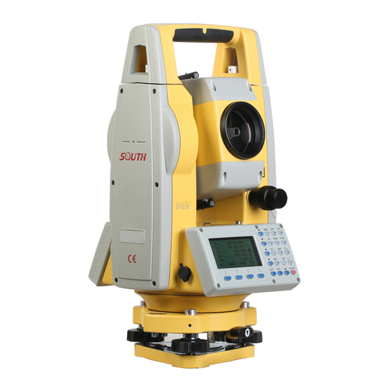
2.BASIC OPERATIONS AND SETTINGS 2.1 Brief Introductions Handle Vial Screw Battery Horizontal Clamp Tangent Unit Battery Lock Optical Unit Power Key Optical Focusing Ring Display Unit Eyepiece RS-232 Comm Port Eyepiece Focusing Ring USB Comm Port Eyepiece Handle SD Card Slot Collimator Circle Bubble Central Mark... -
Page 12: Basic Keys
2.1.1 Basic Keys Distance/Move Down Angle/Move Up Num./Alph.Key Vertical Angle Horizontal Left Cord./Move Left OSET HSET Function Menu Menu/Move Right Power Key Enter Star Key Function Key Name Function Star key Enter the star mode Angle measuring Enter to angle measurement mode Distance measuring Enter to distance measurement mode Coordinate measuring... -
Page 13: Reflector
Sensor closed Bluetooth closed (system setting) (Bluetooth) (Off) Bluetooth open ( system setting) ( Bluetooth) (Open) Reflectorless mode Reflector mode Reflector sheet Battery voltage Display the battery voltage in real time SD Card SD Card inserted 2.1.2 Reflector When measuring distance, a reflector prism needs to be placed at the target place. Reflector systems come with single prism and triple prisms, which can be mounted with tribrach onto a tripod or mounted onto a prism pole. -
Page 14: System Information
2.1.4 System Information Hold the power key in 1s to power on. The initial page is the angle measurement mode (a), press to enter the system information page (b). Press [3] Information to check the hardware information. Hold the power key in 4s to power off. 2.1.5 Initial Settings Mount the instrument to the tripod. - Page 15 of the two leveling screw being adjusted . ② Turn the leveling screw C to move the bubble to the center of the circular vial. 4) Precisely leveling by using the plate vial ① Rotate the instrument horizontally by loosening the Horizontal Clamp Screw and place the plate vial parallel to the line connecting leveling screw A and B, and then bring the bubble to the center of the plate vial by turning the leveling screws A and B.
- Page 16 ③Repeat the steps ①② for each 90º(100g) rotation of the instrument and check whether the bubble is correctly centered in all directions. 2. Centering by using the optical plummet 1) Set tripod Lift tripod to suitable height, ensure equal length of three legs, spread and make tripod head parallel to the ground, and place it right above the measurement station point.
-
Page 17: Star Key
instrument precisely again. Repeat this operation till the instrument collimate precisely to the measurement station point. 2.1.6 Star Key Press to move to activate the Star Key menu, press direction key the cursor, press function keys to operate. Press to exit the menu. (1) Direction keys Reflector: the default setting is NON-P. - Page 18 pointer between on and off. PARA: Parameter setting menu. Input the value of temperature and atmosphere pressure. It will calculate the PPM automatically based on the atmosphere correction. Reference value: Temperature 20 pressure P=1013hPa ℃, 294922 Calculation formula: 003661 ...
-
Page 19: Angle Measurement
When creating a new file, the equipment will create the .SMD and .SCD file under the same name automatically. SMD means South Measure Data, is used for record the data of horizontal disk, vertical disk and SD. SCD means South Coordinate Data, is used for record 3D coordinate for measured points. - Page 20 Format 600 file 180105_1_300.txt Format 300 file 180105_1.dat Coordinate file for SOUTH CASS 180105_1.csv Coordinate file for SOUTH CASS There are some differences between format 600 and format 300 file. Check the picture shown as below. 600.txt included the data in two lines for each measured point. SS line is Point Name, Target Height, Code;...
-
Page 21: F2 Ofset
2.2.1.2 0SET Set the current horizontal angle, press 0SET and YES to confirm. 2.2.1.3 HSET Set the current sight of view as the horizontal input value, the user can separate degrees/ minutes/ seconds by “ . ” 2.2.2 Function Menu in Page 2 2.2.2.1 . -
Page 22: F2 Rep
value is 19°28’ 24” e) Rotate the equipment in clockwise direction, aim at target B in the third time, press F3 REL. f) Rotate the equipment in clockwise direction, aim at target C in the third time, press F 4 HOLD. -
Page 23: Function Menu In
Export to SD card: Press the direction key to move the cursor, press F3 EXP to export the files under SD card. .txt is the measurement data; .dat and .csv are for South CASS software. -
Page 24: Distance Measurement
2.3 Distance Measurement When the current mode is angle or coordinate measurement mode, press to enter the distance measurement mode. 2.3.1 Function Menu in Page 1 2.3.1.1 Save the horizontal and vertical readings into current files. Same to the angle mode, please settle the current files before measurement and data saving. -
Page 25: Function Menu In
2.3.2 Function Menu in Page 2 2.3.2.1. OFSET ① Angle Offset If it is difficult to set up a prism directly, for example the center of a tree, this mode is helpful. It only needs to set the prism on the point which has the same horizontal distance to the instrument as that of the prism to the instrument. -
Page 26: Plane Offset
③ Plane Offset Consider that Point P is on the edge of a plane, which cannot be measured directly through reflectorless mode. Measure P1/P2/P3, the three random prism points on the same plane. Then aim at Point P, it will calculate the coordinate automatically. Steps: A) Aim at P1 and press MEAS. -
Page 27: F2 S.o
Point P1 is the intersection of the straight line OP and the arc, and the P2 and P3 are the left and right end points of the cylindrical diameter. The equipment will calculate the 3D coordinate of point P automatically. Steps: MEAS. -
Page 28: Coordinate Measurement
—— Measured point P1, Target Height 0 65.2838,89.4534,75.958 —— Horizontal / Vertical value, HD of point P1 In .dat profile, which is widely used in South CASS software, the format is “Point Name; Code; E,N,Z” 2.4 Coordinates Measurement When the current mode is angle or distance... -
Page 29: Import And Export From/To Sd Card
2.4.1 Import and Export from / to SD Card. Import the Coordinates of Occupied Point into Known Project: As picture shown,input the coordinates by the order of “Point Name; Code; E, N, Z”. The maximum number of characters for code is 10. Steps: A) Save the file as .csv, it’s a kind of txt format, the users can open it by excel. -
Page 30: Function Key
EXP. To export the file FIX.LIB to SD card. One of the file, FIX.dat is SOUTH CASS format, the data can be recognized as “Point Name; Code; E, N, Z”; the other one FIX.dxf is graphics interchange format, which can be opened by AutoCAD and save as .dwg file. - Page 31 PT CODE BS Point OCC Point Edit the stake-out profile on PC: Input the requested coordinates for point 1/2/3/4, save as “4points.csv” and copy it under the root menu of SD card. Insert SD card into total station. 2.4.2.1 FILE / P3 ①...
-
Page 32: F3 Occ/P2
2.4.2.2 OCC, Occupied Point/P2 OCC to enter the setting page for occupied points(pic a), it will show the Press coordinates of the last occupied point. Press LIST to enter the list of points.(pic b) The list of points will show the point from the known file at first, then the next one is the point from the current file. -
Page 33: F1 Ht/P2
question or hesitate about the backsight direction, please re-operate the “BS” command. On the second page under the coordinate menu, press B.S to set the backsight point.(pic a). There are two methods: a) Press 1( backsight by coordinate) to enter the backsight menu. Press LIST to call the existed point. - Page 34 Step: A) On the 1/2 menu, press 3.LAYOUT PT to enter the stake out function. LIST to show the list of points. The cursor will remain in the first page B) Press automatically. Press to check the detail coordinate (pic d); Press ENT and input target height, again for confirming.
-
Page 35: F1 All/P1
SD card. The dat and csv file can be used in SOUTH CASS software; the dxf file is the graphics interchange format, which can be recognized in AutoCAD and save as dwg format. -
Page 36: Side Shot
Excel. 2.4.3 Side Shot S.O in P3. If the view between the occupied point to stake-out point has been Press covered, the user can execute “Side Shot” or “Resection” command to add the occupied point. Enter the Side Shot menu. Input P1 as the point name, aim at the target center. MEAS to measure the coordinate of point P1. -
Page 37: Distance Resection
YES to record the data under the current job. Then 2.4.4.2 Distance Resection The distance resection method should include at least 2 known points to calculate the coordinate. The steps are similar to angle resection methods. The only thing you should notice is press DIST after aiming at the target. -
Page 38: Adjustment & Information
3.ADJUSTMENT & INFORMATION The structure underlying the Menu system as below: 1.Collect Seq →1.EDIT-MEAS/ 2.MEAS-EDIT 2.Data Confirm →1.ON/ 2.OFF 3.Select SD/HD →1.SD&HD/ 2.HD&VD 1.Meas.File 2.Coord.File 1.OCC.PT Input 3.Pcode File 1.Meas. Data 2.Backsight 4.Fixed File 2.Coord.Data 3.FS/SS 5.U Disk Mode 3.PCode Data 4.Resection 1.Send Data 4.Fixed Data... -
Page 39: Adjustment
4.Comm Parameters 5.Grid Factor 3.1 Adjustment Press 1.ADJUSTMENT in 2 page of Menu. It included four commands: V0 Adjustment, Collimation, Horizontal Axis and V0/Axis Const. The last V0/Axis Const. Will display the results about the previous three commands. Please execute the last command before the to 3 command to clear the existed results. -
Page 40: Collimation (2C)
If the vertical angle is Horizontal 0, i =(L+R-180°)/2 or (L+R-540°)/2 3.1.3 Collimation (2C) Calculate the error of 2C to adjust the horizontal reading, by measuring a clear target in two sides. OK. Rotate the equipment to Aiming at a target in HL, press 2.Collimation (pic b) and OK to finish the adjustment. -
Page 41: Instrument Constant & Information
3.2 Instrument Constant & Information 3.2.1 Inst. Constant Press 2.INST.CONSTANT in the 2 page of Menu(pic b). The default value is 0. Don’t modify the value without the authorization. 3.2.2 Information Press 3.Information in the 2 page of Menu (pic b) ①MB: 03/20180126 - Mainboard 03, update date is Jan.26th, 2018 ②EDM: 05/20161110 - EDM 05, update date is Nov.10th, 2016 ③CCDV: 19/20160629 - Horizontal Disk 19, update date is Jun.29th, 2016... -
Page 42: Mode Set
In “unit set” mode, press 4.Temp.&Press to select the unit of temperature and pressure. ①Temperature Unit When the cursor remain at the 1 line, press OK to confirm. ℉ ℃ The default select is ℃ ②Pressure Unit hPA, mmHg, inHg, and press When the cursor remain at the 2 line, press OK to confirm. -
Page 43: Other Set
3.3.3 Other Set 3.3.3.1 Min Angle Read In the 1 page of “Other Set”, press 1.Min.Angle Read to set the minimum angle reading. Press 1/2/3/4 to select 1s/5s/10s/0.1s. The default set is 1s. 3.3.3.2 Min Dist Read In the 1 page of “Other Set”, press 2.Min.Dist Read to set the minimum distance reading. -
Page 44: W-Correction
3.3.3.7 W-Correction Press 1.OFF to off the w-correction. It will set the w-correction, k=0; Press 2.0.14 to set the w-correction, k=0.14; Press 3.0.2 to set the w-correction, k=0.2. The default value is 0.14 *k is the earth curvature and atmospheric vertical refraction coefficient, also known as w-correction. -
Page 45: Data Collect, Storage & Stake-Out
4.DATA COLLECT, STORAGE & STAKE OUT 4.1 Data Collect The “Data Collect” in the first page of menu, is used for measure and save the 3D coordinates under the current coordinate file, and save the observation data under the current measure file. 4.1.1 New Job Press 1.Data Collect in the first page of menu, enter the file selecting page, the equipment will show the latest file name on the screen. -
Page 46: Set The Occupied Point
refers to Chapter 2.4.1) 4.1.2.1 Set the Occupied Point Press 1. OCC.PT INPUT under the “Data Collect” menu (pic a), it will display the latest occupied point on the screen. (pic b is the default setting) A. Press LIST to enter the point list (pic c), move the cursor to the known point K3, press ENT to view the coordinate of K3(pic d), Press ENT. -
Page 47: Fs/Ss
direction is available, or if there is any question or hesitation about the changes, please execute the backsight setting separately. ① BS COORD A. Press 2.BACKSIGHT and 1.BS COORD under the “Data Collect” menu(pic b), the ENT to confirm. The screen will show the latest backsight point(pic c). -
Page 48: Resection
MEAS and NEZ to measure the distance, example shown as pic e. B. Press C. Press YES to save the data to the current file and back to FS/SS page(pic f). D. The point name will increase automatically, for example from 1 to 2. Finish the measurement of four points based on previous steps. -
Page 49: Collect Sequence
4.1.5.1 Collect Sequence In “Config” page, press 1.Collect Seq to set the sequence. The default setting is “EDIT→ MEAS” ① EDIT→MEAS: Set the point name, code and target height before measure the points. ② MEAS→EDIT: Measure the points before edit the point name, code and target height. 4.1.5.2 Data Confirm In “Config”... -
Page 50: Memory Management
4.2 Memory Management The “Memory MGR” in the first page of menu, press 3. to enter the management mode. 4.2.1 File Maintain Press 1.File Maintain under the “Memory MGR” page. 4.2.1.1 MEAS. FILE Press 1.MEAS.FILE under “File Maintain” page, the cursor will remain in the line of current file. -
Page 51: Pcode File
MEAS. FILE. 4.2.1.3 PCODE FILE Before the measurement, you can create a TXT file on PC to edit codes, each code appears on its own line within 10 characters. Copy the TXT file from SD card to he equipment, as below picture shown: Press 3.PCODE FILE under “File Maintain”... -
Page 52: Fixed Data
4.2.1.4 FIXED DATA Press 4.FIXED DATA under the “File Maintain” menu (pic b) to enter the list of coordinate files. The file name is FIX.LIB which is not able to edit; the number refers the quantity of coordinates. Press EDIT or to view the list of known points. -
Page 53: Data Transfer
4.2.2 Data Transfer Press 2.Data Transfer under the “MEMORY MGR” menu (pic b), press 1.SEND DATA or 2.LOAD DAT for data sending (pic c) or loading (pic d). 4.2.2.1 Connection between N6 and PC ① By USB Connect N6 and PC by USB cable, activate the transform software “NTS-360LNB.exe”. The software shown as below picture: Click “COM para”... -
Page 54: Send Data
4.2.2.2 Send Data N6 can transfer four types of data to PC: measure data, coordinate data, Code data and fixed data. The data is saved in flash memory under the format of file. Please activate the transfer software before sending data. Using measure data as an example. -
Page 55: Edit The Known Coordinate
Use coordinate data as an example: ① Activate the software, click “Folder” button and select the file “4points.csv”. Then click “COM up” button ② Press 1.LOAD COORD. Under “LOAD DATA” menu (pic a) and enter the page for file LIST, NEW and ENT to create a new file by current selection (pic b). -
Page 56: Select The Code File
(pic a). But in PCODE FILE, press to view the contents of code file. 4.2.5 Disk Attribute Press 5.Disk Attr under the “MEMORY MGR” menu (pic b), the cursor will remain in the first line “FLASH” in default. ATTRIB or Press to check the attribute of flash memory (pic c), the capacity for N6 is 4.00MB. -
Page 57: Set The Occ Pt And Bs Pt
4.3.1 Set the Occupied Point and Backsight Point The steps same as Chapter 4.1.3 Set the Occupied Point and Backsight Point. 4.3.2 Set the Layout Point Press 3.Layout PT under “LAYOUT” menu (pic b). Press LIST to enter the point list (pic d), the cursor will remain in the first point automatically (pic c). -
Page 58: Side Shot
4.3.3 Side Shot If the view between the occupied point to stake-out point has been covered, the user can execute “Side Shot” or “Resection” command to add the occupied point. Please check Chapter 2.4.3 Side Shot as the reference. Press 4.Side Shot in the first page of LAYOUT to enter the Side Shot menu (pic a). Input P1 MEAS to measure the coordinate as the point name, aim at the target center. -
Page 59: Programs
5.PROGRAMS Press 4.Programs in the first page of Menu to enter the system programs. The programs on N6 included REM, MLM, Z coordinate, area measurement, point to line and roads. In this chapter, we will talk the all those programs in detail except road. The description of road will be described separately. -
Page 60: Mlm
5.2 MLM MLM function is mainly used for the measurement of HD/VD/SD/HL/HR between two arbitrary points. The coordinate of points can be invoking from the known file or current file, inputting by manual or measurement. Press 2.MLM in program menu (pic a) to select the coordinate file (pic b). Press ENT to select the file and enter the MLM page(pic c). -
Page 61: Calculate By Coordinate Invoking
Press NEXT to repeat step-2 and aim at the target center of point C (pic g). Press MEAS, the dSD, dHD, dVD and HR from point A to C will be shown on the screen (pic h) Press NEXT to repeat the steps, press to exit. -
Page 62: Mlm-2 (A-B B-C)
Press NEXT to repeat step-2 (pic i). Press LIST and move the cursor to Q3 (pic j), to view the coordinate of Q3 (pic k). Press YES, the dSD, dHD, dVD and HR from point A to C will be shown on the screen (pic l). -
Page 63: Z Coordinate
5.3 Z Coordinate Press 3.Z coordinate to enter the coordinate selecting page (pic b), press ENT to confirm. Press 1.OCC PT INPUT to input or call the occupied point. Press 2.REF MEAS to calculate the Z coordinate inversely by distance measurement. And using the calculated coordinate to replace the current one. -
Page 64: Area
YES to well-set the equipment (pic n). point 4 (pic m). Press In “Z Coordinate” page, press 1.OCC.PT INPUT to enter the next page as picture o shown. NEZ to view the coordinate for current Point 4 will be shown on the screen, press occupied point. -
Page 65: Point To Line
order of point 1→point 2→point 3.., by clockwised or anti-clockwised direction. UNIT to change the unit for area or perimeter. After the measurement, press 5.5 Point to Line As picture shown, the theory of point to line is: measure the distance between two arbitrary point P1 and P2, set P1 as original point, azimuth from P1 to P2 as N axis. - Page 66 MEAS, the dSD, for 2 point (pic f). Aim at the prism center of point P2 (pic g), press dHD and dVD from point P1 to P2 will be shown on the screen (pic h). Press OCC to view the coordinate of point A under the independent coordinate system (pic i);...
Need help?
Do you have a question about the N6 Series and is the answer not in the manual?
Questions and answers