Table of Contents
Advertisement
Quick Links
Advertisement
Table of Contents

Related Manuals for South N40 Series


Summary of Contents for South N40 Series
- Page 1 Operation Manual N40 Series Mechanical Total Station...
- Page 2 © South Surveying & Mapping Technology CO.,LTD All Rights Reserved...
-
Page 3: Table Of Contents
CONTENTS PRECAUTIONS…………………...……………………………………………..1 1. INTRODUCTION…………………………………………………………..…2 1.1 Appearance…………………………...………………………………….2 1.2 Keyboard…………………………………………………………………..3 1.3 Screen……………………………………………………………………...4 1.4 Status Icon…………………………………………………………………4 1.5 Abbreviation………………………………………………………………4 1.6 Star Key…………………………………..…………………………………5 1.7 Time & Date………………………………………………………………..7 2. OPERATION………………………………………………………………….8 2.1 Preparation………………………………………………………………..8 2.2 Instrument Setup. ………………………………………………………..8 2.3 Battery…………………………………………………………………….10 2.4 Tribrach…………..……………………………………………………….11 2.5 Eyepiece Focusing……………………………………………………..12 2.6 Input Mode……………………...……………………………………….12 3. - Page 4 4.1 Raw Data………………………………………………………..……..17 4.2 Coord Data…………………...…………………………………………17 4.3 P-Code……………………...………………………………………….…18 4.4 Graphics…………………..………………………………………….…..18 5. COGO…………………………………………………………………..…..19 5.1 Calculatr…………………………………………………………….…..19 5.2 Cal.XYZ …………………………………………………………………...19 5.3 Inverse…………………………….…………………………………..…20 5.4 Area & Perimeter……………………………….…………………..…..21 5.5 Pt-L Inverse……………………………………………………………….21 5.6 2Pts Intersec…………………………………………………………..….22 5.7 4Pts Intersec……………………………………………………..……….23 5.8 Volume…………………………………………………………….……...23 5.9 Unit Switch...………………………………………………………..…….24 5.10 Meridian Convergence……………………………………..……….24 5.11 Traverse Ad.
- Page 5 6.12 App Install………………………………………………………………31 7. ADJUST……………………………………………………………...………32 7.1 Compensator……………………………………………………..……..32 7.2 V0 Adjustment……………………………………………………..…….32 7.3 Constant……………………………………………………………..…...33 7.4 LCD Adjustment………………………………………………………..34 7.5 Gyro Correction………………………………………………………...34 8. MEASUREMENT…………………………………………………………….35 8.1 Angle…………………………………………………………………..….35 8.2 Distance……………………………………………………………….….35 8.3 Coordinates…………………………………………………….………..36 9. STATION………………………………………………………….…………37 9.1 Known Point…………………………………………………….………..37 9.2 Station Ht………………………………………………………………….38 9.3 BS Check……………………………………………………….………...38 9.4 Resection……………………………………………………………..….39 9.5 Gyro Seeking…………………………………………………………….39 9.6 Point to Line………………………………………………..…………….39 9.7 Multi Direction……………………………………………..…………….40 10.
- Page 6 10.9 F1/F2…………………………………………………………………..…48 10.10 Camera……………………………………………………….……….49 11. STAKE OUT………………………………………………………………...50 11.1 Point S.O…………………………………………………..…………….50 11.2 Ang & Dist. S.O…………………………………………..……………..51 11.3 Alignment S.O………………………………………………………….52 11.4 Reference Line…………………………………………………………52 11.5 Line S.O……………………………………………………...…………..54 12. ROAD………………………………………………………………………56 12.1 Select Road……………………………………………………….……56 12.2 H Alignment……………………………………………………...……..56 12.3 V Alignment…………………………………………………….………58 12.4 Road Stake Out………………………………………………………..59 12.5 Road Coord.…………………………………………………………...60 13.
-
Page 7: Precautions
PRECAUTIONS Congratulations on the purchase of SOUTH N40 Series Total Station! Please read carefully through the User Manual before you switch on the product. 1. Do not collimate the objective lens directly to the sunlight without a filter. 2. Do not stare at the laser beam, or point the laser to the others’ eye! 3. -
Page 8: Introduction
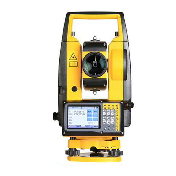
1. INTRODUCTION 1.1 Appearance Description Description Handle Collimator Camera (Optional) Eyepiece Objective Lens Vertical Tangent Screw Battery Unit Vial Bubble Horizontal tangent Screw Plummet EDM Trigger Key Display Unit with Keypad Tribrach Tribrach Lock... -
Page 9: Keyboard
1.2 Keyboard Quick Access Key Functional Key Alphanumeric Keypad Navigation Key Description Shift the case of alphabets. α Activate the soft-keypad Star-key Power On/Off. Func Quick-access to angle measurement Ctrl Quick-access to distance measurement Quick-access to coordinate measurement Delete characters before cursor Switch the cursor in different widget Backspace. -
Page 10: Screen
1.3 Screen It can be divide into four parts: A) Title B) Status Bar C) Active Field D) Tab Bar 1.4 Status Icon Icon Description Display the battery status. Click for power manage. Bluetooth status. Star-key. Click to activate the quick-setting page. Soft-keypad. -
Page 11: Star Key
1.6 Star Key Click [ ] key in any page to activate the quick-setting page. 5) Meas. Mode 1) PPM 6) Pointer 2) Target 7) Plummet 3) E-Bubble 8) Auto Code 4) Calculator ▶ Star Key 1.6.1 PPM The value of temperature, pressure detected calculated by T&P sensor, or inputted by manual. - Page 12 1.6.3 E-Bubble Activate the tilt sensor (electronic bubble) for levelling. X: Turn on the sensor by single axis. XY Turn on the sensor by dual axis. OFF: Turn off the sensor. ▶ Electronic Bubble : Click to turn on or off the laser plummet.
-
Page 13: Time & Date
1.6.7 Plummet Click status illumination level from class 1 to 5. If your total station features the Auto Height function, click [Meas] measure the instrument height. ▶ Laser Plummet 1.6.8 Auto Code Click to activate the Auto Code function. Note: Please refers to Chapter 4.3 P-Code for further information. -
Page 14: Operation
2. OPERATION 2.1 Preparation Unpacking Lay down the case lightly with the cover upward. Unlock the case, and take out the instrument. Storage of Instrument Cover the cap, put the instrument into the case with the vertical clamp screw tightened and circular vial upwards (lens towards tribrach). 2.2 Instrument Setup 1) Setting up the tripod A. - Page 15 Instrument setup (Optical plummet) Adjust the eyepiece of the optical plummet telescope to your eyesight. Slide the instrument by loosening the tripod screw; place the point on the center mark of the optical plummet. Sliding the instrument carefully as to not rotate the axis will allow you to get the least dislocation of the bubble.
-
Page 16: Battery
to center the bubble once more. C. Repeat the steps and check whether the bubble is correctly centered in all directions. If the laser or optical plummet doesn’t stay at the center position after levelling, please slightly loosen the screw under the tripod head and move the instrument (don’t rotate the instrument) until the equipment is on the station point. -
Page 17: Tribrach
Charging The battery must be charged prior to using before the first time operation. The battery LI-39 should be charged only by the official charger NC-III, which packed together with the instrument. Please connect the power supply in 220V, among 0° ~±45° C. When the indicator on the charger is red, the charging process has begun. -
Page 18: Eyepiece Focusing
and take off the instrument. Mounting Insert three anchor jaws into holes of tribrach and line up the directing stub. Turn the locking knob about 180° clockwise to mounting the instrument. 2.5 Eyepiece Focusing Sight the Telescope to bright place and rotate the eyepiece tube to make the reticle clear. -
Page 19: Job
3. JOB In job management, you can create, open, delete or save job as the other file, recover the job from recycle bin, check the information, or import / export data via SD card, flash disk, Bluetooth or Comm Port. Every time when turn on the instrument, it will open the previous job as default. -
Page 20: Delete
3.3 Delete [Delete]: Delete the chosen job. It will be moved into recycle bin. 3.4 Save As Save the current job as a new job. Job: Input the name which will be saved as. Maximum 8 characters. 3.5 Recycle Bin Recover or delete the files in recycle bin. -
Page 21: Information
3.6 Information Check the information of current job. Including the quantity of points & codes, the name of operator, note and create time. 3.7 Import Import data to current job. Imp to: RAM, SD Card, U-Disk and Bluetooth. Via: Txt or Job. Data: Choose data... -
Page 22: About
3.9 About Check the information of total station. Version: Firmware version. Mode: Model name. SN#: Serial number. Device ID: Unique device ID for this unit MAIN: Mainboard version. Boot: Boot version. ANGV/ANGH: Version of vertical and horizontal angle. EDM: Version of EDM board. TILT: Version of tilt sensor. -
Page 23: Data
4. DATA You can view, add, delete or edit the data under current job. Raw Data Coord Data P-Code Graphics 4.1 Raw Data Check and edit the raw data. [First]: Check the first data. [Last]: Check the last data. [Edit]: Edit the selected data. Only point name and code can be edited. -
Page 24: P-Code
4.3 P-Code Delete, edit or add the codes. Auto Code: Enter the auto code (eg. 01, 02, 03), N40 will input the code (eg. tree, lamp, tower) automatically. Note: the auto code function can be turn on or off under Star Key. 4.4 Graphics View and search points by graphics. -
Page 25: Cogo
5. COGO 1) Calculator 7) 4 Pts Intersection 2) Cal.XYZ 8) Volume 3) Inverse 9) Unit Switch 4) Area & Perimeter 10) Meridian Con 5) Pt-L Inverse 11) Traverse Ad. 6) 2 Pts Intersection 5.1 Calculatr [Clr]: Clear all the calculation. [Past]: Paste data... -
Page 26: Inverse
Azimu: The initial azimuth. +Ang: The angle which added from the start point. HD: The horizontal distance which added from the start point VD: The vertical distance which added from the start point [Cal.]: Calculate the coordinate [Save]: Save the coordinate 5.3 Inverse Calculate the unknown relationship (azimuth, HD, SD, VD and slope rate) -
Page 27: Area & Perimeter
5.4 Area & Perimeter Calculate the area and perimeter by at least 3 points. [Add]: Add a new point to the end of list. The points can be created, inputted or selected from data list. [Insert]: Insert a new point before the selected point. -
Page 28: 2Pts Intersec
[Cal.]: Calculate the coordinate and distance between P1-P4/P3-P4. [Save]: Save the coordinate of P4. 5.6 2 Pts Intersec According to two start points, and the relationship (angle/ distance) between these two points, the coordinate of intersection point can be calculated. The known point P1 and P2 can be measured, inputted or selected from data list. -
Page 29: 4Pts Intersec
5.7 4 Pts Intersec Calculate intersection point of two lines (P1-P2 and P3-P4)which are formed by four points. Start P1: The start point of line P1-P2 End P2: The end point of line P1-P2 Start P3: The start point of line P3-P4 End P4: The end point of line P3-P4 intersection point... -
Page 30: Unit Switch
[Del.]: Delete the selected point. [Del All]: Delete all points in the list. [Cal.]: Calculate the volume. [Add All]: Add all the points from current job. Maximum 200 points. [Bulk Add]: Add several points. [Add a Pt]: Add a single point. 5.9 Unit Switch Switch the unit among distance, angle, area, volume and temperature. -
Page 31: Traverse Ad
5.11 Traverse Ad. St.Pt: Input start point of traverse. End Pt: Input end point of traverse KnownPt: The known point which corresponding to the End point. Close Err: Close error Azimuth: Azimuth angle Refer.Err: Reference error Adjust the coordinate and elevation for the traverse. -
Page 32: Setting
6. SETTING Change the settings of below items: 1) Unit 7) Power Manage 2) Angle 8) Others 3) Distance 9) Upgrade 4) Coordinate 10) Format 5) RS232 Comm 11) Initialize 6) Bluetooth 12) App Install 6.1 Unit Angle: d/m/s, Gon, Mil Distance: m, intnl.Feet Temp: ℃, ℉... -
Page 33: Distance
6.3 Distance 6.3.1 Para (Parameter) Scale: 1.000000 in default, can be inputted by manual Ht: Station height TP Sensor: ON, OFF. It can be modified by manual. K: 0.14, 0.20 6.3.2 Mode Click to select the measure mode among N Times (1-99), Continuous, and Tracking mode. -
Page 34: Rs232 Comm
6.5 RS232 Comm RS232: OFF, ON Baud Rate: 4800, 9600, 19200 Bit: 8, 7 Parity: None, Odd, Even Stop: 1, 2 6.6 Bluetooth Bluetooth: ON/OFF Password: Input by manual. 6.7 Power Manage 6.7.1 Powr (Power) Sleep: Set the sleep mode from 0-10 minutes. -
Page 35: Others
6.8.2 Lgt (Backlight) LCD Illum: Activate the auto-backlight mode and double-side mode of LCD display Key Illum: Turn on, off the backlight of keyboard, or set it as auto. Reticle Light: The illumination level of reticle can be selected among 0 to 3. 6.8.3 Set Sound: Turn on or off the sound of operation... -
Page 36: Format
card or U-disk. The software cannot be renamed. Only one upgrade software can be stored in a storage media. 6.9.1 System Ver. Select the storage media, then start the upgrading process. The version will be shown on the screen. 6.9.2 Other Upgrade firmware angle,... -
Page 37: App Install
6.12 App Install Install the third-party software on N40 series total station, if available. Remov: Remove the software Setup: Setup the software... -
Page 38: Adjust
7. ADJUST 1) Compensator 2) V0 Adjustment 3) Constant 4) LCD Adjustment 5) Gyro Correction 7.1 Compensator Please adjust and level the plate vial before calibration of compensator. Aim at a same target precisely by HL/HR and then press [Set] to confirm the adjustment. -
Page 39: Constant
Note: If the index difference does not meet your requirements, please redo the steps. Or contact your local dealer for further help. 7.3 Constant The constant has been checked and adjusted before the shipment, K=0. It’s stable and we advise to check it once or twice in a year. The adjustment should be operated on the base alignment. -
Page 40: Lcd Adjustment
7.4 LCD Adjustment Click the cross-line on the screen to calibrate the sensitivity of LCD display. 7.5 Gyro Correction Input the value of gyro correction, this function only apply to total station which connect with Gyroscope. -
Page 41: Measurement
8. MEASUREMENT 8.1 Angle V: Vertical Angle HR/HL: Horizontal Angle [0Set]: Set the horizontal angle as 0°. [Hold]: Hold the horizontal angle until releasing it. [HSet]: Set the horizontal angle by manual. [V/%]: Switch the display method of vertical angle between value and percentage. -
Page 42: Coordinates
8.3 Coordinates N: North coordinate. E: East coordinate. Z: Elevation [Meas]: Start measurement. [Mod]: Change measurement mode among N times, Continuous and Tracking. [R.Ht]: Input the reflector height. [InH]: Input the instrument height [STN]: Input the coordinates of station. The backsight should be reset. -
Page 43: Station
9. STATION 1) Known Point 5) Gyro Seeking 2) Station Height 6) Point to Line 3) BS Check 7) Multi-Direction 4) Resection 9.1 Known Point Setup the station by known points. The backsight can be defined by coordinate or by angle. Station: Input or select a point from the memory. -
Page 44: Station Ht
9.2 Station Ht Calculate the station height by measuring a point with known height. User should setup the station before calculation. Ht: Input or select the height of known point from data list. InH: Input the instrument height. R.Ht: Input the reflector height. VD: Vertical distance StnH(Cal.): the result of calculated station height. -
Page 45: Resection
9.4 Resection Resection calculate the coordinate of station by known points. [Meas]: Measure the known points. [Del.]: Delete the selected points. [Cal.]: Calculate the points. [Save]: Save and set the station. PtN: Input or select a known point R.Ht: Reflector height. [Angle]: Angle measurement only. -
Page 46: Multi Direction
[InH]: Input or click the button (if your total station features Auto Height function) for instrument height. [Meas]: Measure two points to define a line. d HD: Difference of horizontal distance d VD: Difference of vertical distance d SD: Difference of slope distance [Set]: Click to set the current result as station. -
Page 47: Collect
10. COLLECT 1) Measure Point 6) Line & Ext.Dist. 2) Dist. Offset 7) Line & Ext.Ang. 3) Plane Offset 8) REM 4) Column Center 9) F1/F2 5) MLM 10.1 Measure Pt HD/VD/SD: Measure the point with HD/VD/SD. Click to switch it as N/E/Z. N/E/Z: Measure the point with N/E/Z PtN: Input the point name Code: Input or select the code from... -
Page 48: Dist.offset
10.2 Dist.Offset This function calculates the coordinate of an unknown point based on lateral and longitudinal offset or height difference. ←/→: Left/Right. Select and input the value. Fw/Bw: Frontward backward. Select and input the value. ↑/↓: Upward/Downward. Select and input the value. [Meas]: Measure the point based on offset value. -
Page 49: Plane Offset
10.3 Plane Offset This function calculates the point which cannot be measured directly. N40 will calculate the other three points (A/B/C) in same plane at first. Then aim at the target (P0) to calculate the coordinate and SD/HD/VD [NE Projection]: User can choose the projection among NE/ZE/ZN Projection. -
Page 50: Column Center
10.4 Column Center This function calculates the coordinate of a hidden point (P0) that is not directly visible inside from the surface center (P1) and edge (P2/P3) of column. DirA: Collimate one side of column, press, press [OK] to measure DirB: Collimate the other side of column, press [OK] to measure Centr: Collimate the surface center... -
Page 51: Mlm
10.5 MLM MLM, is mainly used to calculate the HD/ VD/ SD between A-B, A-C or A-B, B-C, etc. Start Pt: Input, select or measure the start point. [Lock]: Lock the start point. Otherwise, it will use the last point as start point. HD: Horizontal distance between start point and measured point. -
Page 52: Line & Ext Pt
10.6 Line & Ext Dist Line & extended distance, this function calculate the unknown point by a line defined by two points and an extent distance HA: The current horizontal angle. VA: The current vertical angle. P1: The slope distance to the first point. P2: The slope distance to the second point. -
Page 53: Line & Ext Ang
10.7 Line & Ext Ang Line & extended angle, this function calculate the unknown by a line defined by two points and an extended angle. HA: The current horizontal angle. VA: The current vertical angle. P1: The slope distance to the first point. P2: The slope distance to the second point to define a line. -
Page 54: Rem
10.8 REM Points directly above the prism can be determined without a prism at the target point. VA: Current vertical angle. dVD: Vertical distance of target R.Ht: Reflector height. VA: Vertical angle of prism point HD: Horizontal distance of prism point [Angle]: Measure the angle [Dist&Angle]: Measure the angle and distance together. -
Page 55: Camera
10.10 Camera (Optional) You can do the target shooting, display setting, saving in this program Setting the camera images Zoom in Zoom out Save... -
Page 56: Stake Out
11. STAKE OUT 1) Point S.O 2) Angle & Distance S.O 3) Alignment S.O 4) Reference Line 5) Line S.O 11.1 Point S.O Pt: Input, measure or select a known point. [Last]: Back to the last stake-out point. [Next]: Select the next stake-out point. HA: Horizontal angle of stake-out point. -
Page 57: Ang & Dist S.o
F&D: Move the target upward (Fill) or downward (Dig), until 0. [Meas]: Measure the target, then move it based on the guidance. [Save]: Save the current point. 11.2 Ang & Dist S.O Stake out a point by angle (azimuth) , distance (HD) and elevation (z). -
Page 58: Alignment S.o
11.3 Alignment S.O Stake out a point by a known point and the related angle (HA), distance (HD) and elevation (Z). PtN: Input, measure or select a known point. Azimu: Input the azimuth angle from the known point to the stake-out point. HD: Input the horizontal distance. - Page 59 1)Define the base line The base line is fixed by two known points – start point and end point. Those two points can be inputted, selected or measured. 2)Shift the reference line ▶ Define the reference line base line offset longitudinally, parallel and vertically or rotated.
-
Page 60: Line S.o
4)Stake-out the target The program calculates the difference between the measured point and the calculated target point. Find the stake-out point until the value becomes 0. 11.5 Line S.O S.O Line Base Line This function calculates the coordinate of stake-out points by a base line EndPt EndPt’... - Page 61 calculated target point. Off.: Move parallelly find stake-out points, until it becomes 0. L.: Length from start point. ↑ / ↓ : Move vertically to find the stake-out points, until it becomes 0. ▶ Stake out the points [Back]: Back to previous step. [Meas]: Measure the target until the offset becomes 0.
-
Page 62: Road
12. ROAD This program enables users to easily define a line, curve or transition curve as a reference to measure or stake out. Before starting the roads, please set job, station and backsight at first. 12.1 Select Road Select or create a new road under the current job. - Page 63 Start Point The elements of start point included the start mile (St Mile), initial coordinate (N/E) and azimuth (Azimu.). ▶ Start Point Line The element of straight line only included the length. Note: The value of length should be positive. ▶...
-
Page 64: Alignment
Transition Curve elements transition curve included parameter (Para.), start radius (Start R) and ending radius (End Note: The value of parameter depends on the forward direction of curve. When the curve turns right, the value should be positive; Otherwise, it should be negative. -
Page 65: Road Stake Out
12.4 Road Stake Out Interval: Interval between stake-out points. Offset(R) Offset(L) Offset: The left and right offset from the center line. Start Pile: Start pile for road stake-out. Interval Interval: The interval between the stake-out points. ←/→: The left or right distance offset based on the center line. -
Page 66: Road Coord
12.5 Road Coord. After setting the horizontal and vertical alignment, the coordinates can be calculated and saved. You can find those points in data list, then stake out the calculated points separately. St Mile: The start mile of calculation. End Mile: The end mile of calculation. Interval: The interval of the points Start Pt: The start point of calculation. -
Page 67: Inspection & Adjustment
13. INSPECTION & ADJUSTMENT The instrument has passed the procedure of inspection and adjustment before shipping to your side. However, after long periods of transportation or the changeable environment, some influences may occur to the internal structure. Before the instrument is used for the first time, please check and adjust the functions we introduced in this session to ensure the precision of the job. -
Page 68: Circular Vial
13.2 Circular Vial Inspection It is not necessary to adjust the circular vial, except the bubble is not in the center after the adjustment of plate vial. Adjustment If the bubble of the circular vial is not in the center, adjust the bubble to the center by using the adjusting pin or hexagon wrench. -
Page 69: Inclination Of Reticle
Adjustment Please refers to Chapter 7.1 Compensator for adjustment. Repeat the steps for double check. If the deviation still overrange, please contact your local dealer for further help. 13.4 Inclination of Reticle Inspection 1. Sight object A after leveling the equipment, lock the horizontal and vertical tangent unit and confirm the target A is in the center of reticle. -
Page 70: Perpendicularity Between Sight Of View & Horizontal Axis
3. Tighten the adjusting screws slightly. Repeat the previous steps to see whether the position is correct. 4. Assemble the eyepiece cover back. 13.5 Perpendicularity between Sight of View & Horizontal Axis (2C) Inspection 1. Set object A at a far distance at the same height as the instrument, leveling the instrument and turn on the power (e.g. -
Page 71: Vertical Index (I Angle) & V0 Adjustment
reading which has been eliminated C: R+C=190°13′40″-15″=190°13′25″ 2. Take off the cover of the reticle between the eyepiece and focusing screw. Adjust the left and right adjusting screws by loosening one and tightening the other. Move the reticle to sight object A exactly. 3. -
Page 72: Optical Plummet
13.7 Optical Plummet Inspection 1. Set the instrument on the tripod and place a piece of white paper with a cross lines on it below the equipment. 2. Adjust the focus of optical plummet. Move the paper until the intersection point of the crossline on the paper comes to the center of optical plummet. -
Page 73: Laser Plummet
13.8 Laser Plummet Inspection Activate the laser plummet, from star key - Plummet Repeat the inspection steps as Chapter 13.7 If the laser point keep coincide with the intersection point, it is not necessary to adjust. Adjustment If the laser plummet was broken, please contact your local dealer to change a new one. -
Page 74: Coincidence Between Sight Of View % Emitting Axis
inspection value. Adjustment Prism Const: The additive constant of the prism mode. Non-P Const: The additive constant of non-prism mode. Note: Set the orientation through the vertical reticle to ensure Point A,B, and C on the same line. It must has a fixed and clear centering mark on Point B. -
Page 75: Leveling Screws On Tribrach
2. Aim and measure the center of target. 3. Rotate the tangent screw to launch electric collimation and make the light path of EDM unblocked. In the bright zone, find the center of emitting photoelectric axis. 4. Check whether the center of reticle coincide with the center of emitting photoelectric axis. -
Page 76: Specifications
14. SPECIFICATIONS TELESCOPE Image Erect Tube length 152mm Effective aperture 45mm (DTM: 47mm) Magnification Field of view 1°30’ Resolving power 3” Minimum focus 1.5m Reticle illumination 4 brightness level ANGLE MEASUREMENT Accuracy 2” Measuring method Absolute encoding Diameter of disk 79mm Minimum reading 1”... - Page 77 Atmospheric correction Manual input, auto correction Prism constant Manual input, auto correction Temperature correction Sensor reading Distance reading Max: 99999999.999m; Min: 1mm COMPENSATOR System Liquid, dual axis Working range ±6’ Accuracy 1” PLUMMET ±1.5mm @1.5m Accuracy Brightness 5 brightness level Laser Wavelength 635nm...
- Page 78 INTERFACE RS-232 serial port Data interface USB, SD card, Mini USB port, Bluetooth BATTERY Type Lithium, 7.4V Operating time 8 hours VIAL Plate vial 30”/2mm Circular vial 8'/2mm GENERAL Storage 98M, 833000 data block IP54 Size 206*200*353mm Weight Approx. 6.0kg * Under good conditions, Kodak Gray card, 80% reflectance...
-
Page 79: Safety Guide
15. SAFETY GUIDE 15.1 Internal Distance Meter (Visible Laser) Warning The total Station is equipped with an EDM of Laser Class 3A/III a and it is verified by these labels as follows: There’s an indication label “CLASS III LASER PRODUCT” above the vertical clamp screw on Face Left as well as on the Face Right. - Page 80 Warning When the laser beam emits on prism, mirror, metal surface, window, it might be dangerous to look directly by the reflecting light. Prevention Do not stare at the direction which the laser beam might reflects. When the laser is opened, do not look at it near to the optical path or the prism.
- Page 81 through the restricted area (harmful distance*), and there are persons taking activities, users must stop the laser beam in time. d. The optical path of the laser beam should be set higher or lower than the line of sight. e. When the laser instrument is not in use, users should keep it well. It is not allowed for operation unless the user is authenticated.
- Page 82 15.2 Laser Plummet The internal laser plummet sends out a ray of red visible laser beam from the bottom of the instrument. This product is classified as Class 2/II laser product. Class 2 laser product is in accordance with the following standard: IEC 60825-1:1993 “SAFETY of LASER PRODUCTS”...
Need help?
Do you have a question about the N40 Series and is the answer not in the manual?
Questions and answers