Table of Contents
Advertisement
Quick Links
Advertisement
Table of Contents

Related Manuals for South N6+ Series


Summary of Contents for South N6+ Series
- Page 1 Operation Manual N6+ Series Mechanical Total Station...
- Page 2 © South Surveying & Mapping Technology CO.,LTD All Rights Reserved...
-
Page 3: Table Of Contents
INDEX 1.SPECIFICATION................1 1.1 EDM..................1 1.2 Others..................2 2.BRIEF INTRODUCTIONS……………………...........4 2.1 Appearance……………..............4 2.2 Keyboard……………..............5 2.3 Star Key……………..……..............6 2.4 Hot Keys……….…………..............8 2.5 System Inforamtion……….……….............8 3.PREPARATION………………………………...........9 3.1 Preparation…...……………………………...........9 3.2 Instrument Setup…...……………………………........9 3.3 Battery………..……...……………………………........11 3.4 Tribrach……..……...……………………………........12 3.5 Eyepiece Focusing...……………………………........13 3.6 Parameters………..……………………………........13 3.6.1 Unit Set................13 3.6.1.1 Feet................ - Page 4 3.6.3.1 Min Angle Read............15 3.6.3.2 Min Dist Read............15 3.6.3.3 Face in L or R............. 16 3.6.3.4 Auto Power Off............16 3.6.3.5 H-Angle Buzzer............16 3.6.3.6 Meas Buzzer..............17 3.6.3.7 W-Correction............17 3.6.3.8 Data & Time..............17 3.6.3.9 Grid Factor.............. 17 3.6.3.10 IMP/EXP Order..............18 3.6.4 Initial Set…………………............18 4.ANGLE MEASUREMENT...............19 4.1 [F1] ALL....................19 4.2 [F2] 0 SET.....................21...
- Page 5 5.7 [F1] OFSET..................29 5.7.1 Angle offset................29 5.7.2 Distance offset................30 5.7.3 Plane offset................30 5.7.4 Column offset................31 5.8 [F2] S.O....................32 5.9 [F3] FILE....................33 6.COORDINATE MEASUREMENT............34 7.MENU....................35 7.1 Data Collect..................36 7.1.1 New Job..................36 7.1.2 OCC PT Input................37 7.1.3 Backsight................38 7.1.4 FS/SS................39 7.1.5 Resection.................39 7.1.6 Config of Data Collect............
- Page 6 7.3.2 Data Transfer..............4 8 7.3.2.1 Connection between N6+ and PC.......49 7.3.2.2 Send Data..............49 7.3.2.3 Load Data..............50 7.3.3 Edit the Known Coordinates..........51 7.3.4 Select the Code File............51 7.3.5 Disk Attribute..............51 8.PROGRAMS................52 8.1 REM..................52 8.2 MLM..................53 8.2.1 MLM-1 (A-B, A-C)............54 8.2.2 MLM-2 (A-B, B-C)............56 8.3 Z Coordinate................5 7 8.4 Area..................5 9...
- Page 7 9.2 Case Study - H Curve in Renovation Project......76 9.2.1 Design Drawing for the H Curve JD17......7 6 9.2.2 Transfer the Form into Linear Elements......76 9.2.3 How to Use N6 to Calculate the Road in H Curve....78 9.3 Case Study - V Curve in Road Project........82 9.3.1 Design Drawing for the V Curve JD39-JD43.....82 9.3.2 Transfer the Form into Linear Elements......83 9.3.3 How to Use N6 to Calculate the Road......83...
-
Page 8: Specification
1. SPECIFICATIONS 1.1 EDM Carrier Wave 0.65~0.69μm Effective Range of Bluetooth Reflectorless Range 1000m/1500m optional Oscillation Frequency 150MHz EDM Type Coaxial Minimum Reading for Distance 0.1mm Laser Dot without Reflector Around 7mm×14mm/20m (Red laser beam) Around 10mm×20mm/50m Atmosphere Correction Manual Input, Auto correction Earth Curvature Correction Manual Input, Auto correction Prism Constant... -
Page 9: Others
− Tracking Mode ± (10+2× · D)mm Max. Range With Reflector Single Prism 5000m *² Good Conditions IR Sheet 1000m Without Reflector White*³ 1000m *² Good Conditions Gray Degree 0.18 450m *¹ D= distance in mm *² Good Conditions: slight haze, visibility about 20km *³... - Page 10 Vial Plate Vial 30”/2mm Circular Vial 8’/2mm Laser Plummet ± 1.5mm( at 1.5m) Accuracy Optical Plummet (OPTIONAL) Image Erect Magnification 0,5m~∞ Focusing Range 5° Field of View Display Unit Type 6 Lines LCD screen Data Communication Port USB Stick up to 256G, Bluetooth Battery Type Rechargeable Lithium battery...
-
Page 11: Brief Introductions
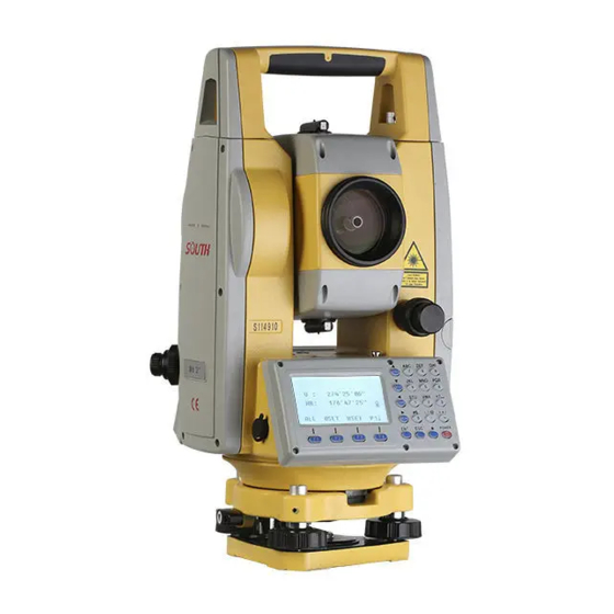
2. BRIEF INTRODUCTION 2.1 Appearance Handle Vial Bubble Battery Lock Horizontal Clamp and Tangent Unit Battery Optical Unit Trigger Key Display Unit Optical Focusing Ring Eyepiece Handle Power Key Eyepiece Focusing USB Comm Port Ring Circle Bubble Eyepiece Tribrach Lock Collimator Leveling Screw Central Mark... -
Page 12: Keyboard
2.2 Keyboard Distance/Move Down Angle/Move Up Num./Alph.Key Vertical Angle Horizontal Left Cord./Move Left Function Key OSET HSET Menu/Move Right Power Key Function Key Enter Star Key Name Function Star key Enter the star mode Angle Enter the angle measurement mode Distance Enter the distance measurement mode measuring... -
Page 13: Star Key
Sensor closed Bluetooth Bluetooth on. Reflectorless mode Reflector mode Reflector sheet Battery voltage Display the battery voltage in real time 2.3 Star Key Press [★] to activate the Star Key menu, press direction key [▲] [▼] [▶] [◀] to move the cursor, press function keys to operate. Press [ESC] to exit the menu. - Page 14 setting is on. Press [F1] to open or close the illumination. TILT: On/Off the tilt sensor. The default setting is dual-axis sensor. Press [F2] to enter 1/2 page. Then press [F1] X-ON for single X-axis compensation, press [F2] XYON for dual-axis compensation. Press [F3] OFF to close the compensator.
-
Page 15: Hot Keys
2.4 Hot Keys When the total station is under the basic measurement surface, click the numeric keyboard to quickly access to the other pages. Quick Access To Stake Out Tilt Sensor Data Confirm Memory MGR. View Meas File View Coord File Resection Created Meas &... -
Page 16: Preparation
3. PREPARATION 3.1 Preparation Unpacking Lay down the case lightly with the cover upward. Unlock the case and take out the instrument. Storage of Instrument Cover the cap, put the instrument into the case with the vertical clamp screw tightened and circular vial upwards (lens towards tribrach). - Page 17 the point on the center mark of the optical plummet. Sliding the instrument carefully as to not rotate the axis will allow you to get the least dislocation of the bubble. 3) Roughly leveling by the circular vial A. Rotate the foot-screw A and B to move the bubble in the circular vial, in which case the bubble is located on a line perpendicular to a line...
-
Page 18: Battery
C. Repeat the steps and check whether the bubble is correctly centered in all directions. If the laser or optical plummet doesn’t stay at the center position after levelling, please slightly loosen the screw under the tripod head and move the instrument (don’t rotate the instrument) until the equipment is on the station point. -
Page 19: Tribrach
operation. The battery LB-01 should be charged only by the official charger NC- 10, which packed together with the instrument. Please connect the power supply in 110V - 220V, among 0° ~± 45° C. When the indicator on the charger is red, the charging process has begun. -
Page 20: Eyepiece Focusing
Mounting Insert three anchor jaws into holes of tribrach and line up the directing stub. Turn the locking knob about 180° clockwise to mounting the instrument. 3.5 Eyepiece Focusing Sight the Telescope to bright place and rotate the eyepiece tube to make the reticle clear. -
Page 21: Distance
3.6.1.3 Distance Select the distance unit among Meter, Feet and Feet.Inch. 1 Meter = 3.280839895 Feet, 1 Feet = 12 Inch. 3.6.1.4 Temp.&Press Select the unit of temperature and pressure. ① Temperature Unit When the cursor remain at the 1st line, press [F1]℃ or [F2]℉ to select the unit of temperature. -
Page 22: Dist Mode
3.6.2.2 Dist Mode Select the measure mode among Fine[S] (single), Fine[3] (3 times), Fine[R] (Repeat) and Tracking mode. Press [F4]OK to confirm. The default set is Fine[S]. 3.6.2.3 NEZ/ENZ Select the display order of the coordinates by NEZ or ENZ. Press [F4]OK to confirm. -
Page 23: Face In L Or R
Press 1/2 to select the minimum distance reading between 1mm and 0.1mm. The default set is 1mm. 3.6.3.3 Face in L or R Press 1.Differ to keep the unequal coordinate between HL/HR direction. Press 2.Equation to keep the equal coordinate, no matter in HL/HR direction. -
Page 24: Meas Buzzer
3.6.3.6 Meas Buzzer Press 1/2 to OFF/ON the function of measurement buzzer. The equipment will activate the buzzer when the measurement has finished in each time. The default set is ON. 3.6.3.7 W-Correction Press 1.OFF to off the w-correction. It will set the w-correction, k=0; Press 2.0.14 to set the w-correction, k=0.14;... -
Page 25: Imp/Exp Order
3.6.3.10 IMP/EXP Order Set the import and export order of coordinate. Press the left or right navigation to switch the settings. NEZ IO ORDER NEZ IO ORDER 1.PT# 1.PT#PT 2.PCODE Z.PT# N.PT# N.PT# EPT# EPT# 1.PT# 5.PCODE ZPT# [OK] [OK] 3.6.4 Initial Set Press 4.Initial Set to recovery to initial settings. -
Page 26: Angle Measurement
4. ANGLE MEASUREMENT When power on the equipment, N6+ will enter the angle measurement mode automatically. Press [ANG] enter angle measurement mode. 4.1 [F1] ALL Measuring and saving the data of angle. Q.: Setup a station at Point A, how to measure the horizontal angle for Target B/C by multiple round observation? a) Aim at target B in Horizontal Left (HL), press [F3] HSET , input value as 0°00’... - Page 27 Press [F4] P1/P2 turn to page 3, then click [F4] FILE - [F2] LIST – [F3] EXP to export the data of the current file “180105_1” : 180105_1_600.txt Format 600 file 180105_1_300.txt Format 300 file 180105_1.dat Coordinate file for SOUTH CASS 180105_1.csv Coordinate file for SOUTH CASS...
-
Page 28: F2] 0 Set
There are some differences between format 600 and format 300. Check the picture shown as below. 600.txt included the data in two lines for each measured point. SS line is Point Name, Target Height, Code; while HV line is Horizontal Reading and Vertical Reading. 4.2 [F2] 0 Set Set the horizontal angle of the first target as 0°00’00”... -
Page 29: F1] Hold
4.4 [F1] HOLD Define and hold the horizontal angle of target as previous value. Q.: How to “hold” the angle reading in 90 00’00”? ° a) Rotate the equipment and make the horizontal angle near to 90° 00’00” , then adjust the tangent screw until it’s fully reached the value. - Page 30 c) Rotate the equipment in clockwise direction, aim at target B in the second time, press [F3] REL. to release (pic e). d) Rotate the equipment in clockwise direction, aim at target C in the second time (pic f), press [F4] HOLD, it will show us the horizontal value of ∠BAC during this two times, the average value is 19°28’...
-
Page 31: F3] V
4.6 [F3] V% Switch the reading of vertical angle from vertical degree to percent. As picture shown, if the vertical reading has been set as Zenith 0, HL= 75°00’ 00”. αL=90°−L=90°−75° 00′00″=15° 00’ 00” The slope angle i=100×tan 15° 00’00”=26.7949 %≈26.79%. 4.7 [F1] CPMS Switch the display format of vertical angle. -
Page 32: F3] File
4.9 [F3] FILE In this page, we can change the current job, create a new job, rename or delete the existed job, export or import data. Press [F3] FILE , [F2] LIST to enter the profile list, or press [F3] NUM/ALPH to create a new job. -
Page 33: Distance Measurement
5. DISTANCE MEASUREMENT Press [DIST] to enter the distance measurement mode. OCC. OFFS FILE 5.1 [F1] ALL Measure and record the distance. N6+ will calculate the coordinate of target based on the current station, instrument height and target height, then it will be recorded in coordinate file and measurement file. -
Page 34: F1] Ht
5.4 [F1] HT Set the instrument height or target height (pic b). 5.5 [F2] BS Orient the backsight by point or angle. Select the existed point or enter the angle 300.1.33 to define the backsight. Rotate the equipment to aim at the target K2. Press [F4] YES to set the orientation of backsight. -
Page 35: F3] Occ
5.6 [F3] OCC. Press [F3] OCC to enter the setting page for occupied point (pic a), it will show the coordinates of the last occupied point. Press [F2] LIST to enter the list of points. (pic b) Move the cursor to K3 and press [ENT] to select it. it will show the details of this point, including the code and coordinate. -
Page 36: F1] Ofset
equipment will check and calculate the difference between the known point K3 and the measured point. [F3]NEZ.: Check the coordinate of measured point. [F3]Δ: Check the difference. 5.7 [F1] OFSET 5.7.1 Angle Offset If the target is invisible, it is difficult to set up a prism on the target directly, for example the center of a tree. -
Page 37: Distance Offset
5.7.2 Distance Offset This function calculates coordinate of point based on lateral and longitudinal offset or height difference of the target. Steps: A) Input the offset value, press [F4]ENT to confirm (Pic d) B) Aim at the offset point P, press [F1]MEAS (pic e) C) Press [CORD] to check the coordinate of Point A0. -
Page 38: Column Offset
Then aim at the target (P0) to calculate the coordinate and SD/HD/VD from station. Steps: A) Press [F1]MEAS to aim at P1/P2/P3 to define a plane(pic e) B) Rotate the equipment, aim at point P. It will show the distance between station to Point P(pic f) C) Press [CORD] to check the coordinate of Point A0. -
Page 39: F2] S.o
Press [CORD] to check the coordinate of Point A0. Press [DIST] to check the distance. 5.8 [F2] S.O This function calculates the distance elements (SD/HD/VD) to stakeout points Steps: Use [F1]HD as an example. A) Input the horizontal distance: 2.0m, press [F4]ENT to confirm. B) Rotate the equipment and then ask the prism move to the correct sight of view. -
Page 40: F3] File
K2,0.000,1J —Backsight point K2, Target Height: 0, Code: 1J ENZ 432700.488,2448453.713,2.661 —Coordinate of backsight point P1,000 — Measured point P1, Target Height 0 SD 65.2838,89.4534,75.958 —Horizontal / Vertical value, HD In .dat profile, which is widely used in South CASS software, the format is “Point Name; Code; E,N,Z”. -
Page 41: Coordinate Measurement
6. COORDINATE MEASUREMENT Press [CORD] to enter the coordinate measurement mode. Users can input the coordinates of occupied point by a standard CASS format “Point Name; Code; E, N, Z”, maximum 200 points and save as “.csv” format by Bluetooth or USB Flash Disk. Insert USB flash disk into total station, import the .csv profile into the existed FIX.LIB menu. -
Page 42: Menu
7. MENU The structure underlying the Menu system as below: 1.Collect Seq →1.EDIT-MEAS/ 2.MEAS-EDIT 2.Data Confirm →1.ON/ 2.OFF 3.Select SD/HD →1.SD&HD/ 2.HD&VD 1.Meas.File 2.Coord.File 1.OCC.PT Input 3.Pcode File 1.Meas. Data 2.Backsight 4.Fixed File 2.Coord.Data 3.FS/SS 5.U Disk Mode 3.PCode Data 4.Resection 1.Send Data 4.Fixed Data... -
Page 43: Data Collect
7.1 Data Collect Data Collect, is used for measure and save the coordinates under the current coordinate file, and it will also save the measured data under the current measure file. 7.1.1 New Job Press 1.Data Collect in the first page of menu, enter the file selecting page, the equipment will show the latest file on the screen. -
Page 44: Occ Pt Input
7.1.2 OCC Point Input A. Press [F2] LIST to enter the point list, move the cursor to the known point K3, press [ENT] to view the coordinate of K3(pic d). B. Input the instrument height (pic e) and press [ENT] to confirm. C. -
Page 45: Backsight
7.1.3 Backsight The backsight is able to be oriented by coordinate or by angle. BS COORD [F2] LIST: Select the coordinate from the list. [F3] NUM/ALPH: Enter the coordinate directly as the backsight. BS ANGLE Input the angle as backsight: 300°01’33”(pic c). Aim at the target center of backsight, press [F4]YES to set the horizontal angle as the backsight(pic e). -
Page 46: Fs/Ss
7.1.4 FS/SS Measure and save the coordinate of points. [F1] INPUT: Input the point name, code and target height (R.HT) [F2] VIEW: Enter the point list. [F3] MEAS: Measure angle, distance, or coordinate [F4] ALL: Measure and save 7.1.5 Resection A resection sets up the station by using the angle and distance measurements... - Page 47 Steps: Input P1 as the unknown station, and the equipment height (pic b). Press [F4]ENT to the measure page. Input the known point Q1. The system will select Q1’s coordinate from list. Aim at the prism center of Point Q1 (pic f). Press [F3]ANG to measure the angle.
-
Page 48: Config Of Data Collect
Resection by Distance The distance resection method should include at least 2 known points to calculate the coordinate. The steps are similar to angle resection methods. The only thing you should notice is press [F4] DIST after aiming at the target. 7.1.6 Config 7.1.6.1 Collect Sequence Set the sequence. -
Page 49: Stake Out
7.2 Stake Out Press [F2]LIST to view the file list (pic), move the cursor to select the file where you saved the data. 7.2.1 Layout Pt Press [F2]LIST to select a point from the list (pic d), Press [F1]VIEW to check the detail information for the selected point. -
Page 50: Side Shot
7.2.2 Side Shot If the stake out point is invisible, we can use Side Shot to add another point as station to find the target. Input P1 as the point name, aim at the target center. Press [F4] MEAS to measure the coordinate of point P1. Then press [F4] YES to record it. -
Page 51: File Maintain
7.3 Memory MGR. 7.3.1 File Maintain Create, import, export, check, rename or delete the files. 7.3.1.1 Meas File [F1]NEW: Add a new file, the system will create two files, “SMD” and “SCD”. “SMD” for measurement data, while “SCD” for coordinate data. -
Page 52: Pcode File
7.3.1.3 Pcode File Before the measurement, you can create a TXT file on PC to edit codes, each code appears on its own line within 10 characters. Copy the TXT file from, as below picture shown: [F1]NEW: Input the code name “CODE1” (pic c) [F2]IMP: View the file list under the root directory of USB stick, move the cursor to the file you need (pic e) and press [ENT] to import the code file to CODE1, the equipment will back to the file list... -
Page 53: Known Coord
7.3.1.4 Known Coord. Press 4.Known Coord. under the “File Maintain” menu (pic b) to enter the list of coordinate files. The file name is FIX.LIB which is not able to edit; the number refers the quantity of coordinates. Import the Coordinates of Occupied Point into Total Station: As picture shown, input those coordinates by “Point Name;... - Page 54 4.KNOWN COORD Export the Coordinates of Occupied Point to USB Stick: Press [F3]EXP. To export the file FIX.LIB to USB stick. FIX.dat is SOUTH CASS format, the data can be recognized as “Point 4.KNOWN COORD Name; Code; E, N, Z”; the other file FIX.dxf is a graphics interchange...
-
Page 55: Data Transfer
Edit the Coordinates of Occupied Point: [F1]VIEW: Check the coordinate of the first known point (pic d), press [△] or [F3]END to check the last point (pic e) [F2]SRCH: Search known points. (pic h); Press [F1]EDIT to edit the selected point. [F3]DEL: Delete the selected point. -
Page 56: Connection Between N6+ And Pc
7.3.2.1 Connection between N6+ and PC N6+ only can connect to PC transfer software by Bluetooth. Click “Start” icon on a laptop which features Windows 10 system and Bluetooth in the same time. Choose “Setting - Device - Bluetooth” to open the Bluetooth connection and search the equipment. -
Page 57: Load Data
Click “Receive” button on PC before press [ENT] on N6+ to send the selected file. Click “Save” button on PC to save the file after receiving data from total station. 7.3.2.3 Load Data N6+ can transfer three types of data from PC: coordinate, Code and known point. -
Page 58: Edit The Known Coordinates
③ Click “SEND” button on PC to activate the software, the equipment will show the process for data loading in real-time 7.3.3 Edit the Known Coordinates Press 3.EDIT under the “MEMORY MGR” to enter the point list (pic b). [F1]VIEW: Check the point name, code, N/E/Z [F2]SRCH: Search the point by point name [F3]DEL.: Delete the selected point [F4]ADD: Add a known point... -
Page 59: Programs
8.PROGRAMS Press 4.Programs in the first page of Menu to enter the system programs. The programs on N6+ included REM, MLM, Z coordinate, area measurement, point to line and roads. In this chapter, we will talk the all those programs in detail except road. The description of road will be described separately. -
Page 60: Mlm
8.2 MLM function mainly used measurement HD/VD/SD/HL/HR between two arbitrary points. The coordinate of points can be invoking from the known file or current file, inputting by manual or measurement. There included two options, MLM-1 (A-B A-C) and MLM-2 (A-B B-C). MLM-1 (A-B A-C) is used for measure the HD/VD/SD/HL/HR from start point A to arbitrary point B,C.., MLM-2 (A-B B-C) is used for measure the HD/VD/SD/HL/HR from two nearly points. -
Page 61: A-B A-C)
8.2.1 MLM-1 (A-B A-C) 8.2.1.1 Calculate by distance measurement. Press [F2]R.HT to input the prism height (pic c), press [F4]ENT to confirm; Aim at target A and press [F1]MEAS for step-2. Aim at target B (pic e) and press [F1]MEAS, the dSD, dHD, dVD and HR from A to B will be shown on the screen (pic f). - Page 62 Use the coordinate of K1/K2/K3 as point A/B/C to calculate the edge. Press 1.MLM-1 (A-B A-C) to enter the step-1 (pic b), press [F4]LIST to enter the point list. The cursor will remain in the first line K1 (pic c), press [F1]VIEW to check the detail for K1 (pic d).
-
Page 63: A-B B-C)
8.2.2 MLM-2 (A-B B-C) 8.2.2.1 Calculate by distance measurement. Press 2.MLM-1(A-B, B-C) to enter the step-1 (pic b); aim at the prism center of point A (pic b) and press [F1]MEAS to measure the distance and enter step-2. Aim at the prism center of point B (pic c), press [F1]MEAS to measure the distance. -
Page 64: Z Coordinate
Press [F4]YES, the dSD, dHD, dVD and HR from point A to B will be shown on the screen (pic h). The value of dHD and HR are same to the value on the picture noted. Press [F1]NEXT to repeat step-2 (pic i). Press [F4]LIST and move the cursor to K3 (pic j), and [ENT] to view the coordinate of K3 (pic k). - Page 65 Press 1.OCC PT INPUT under “Z Coordinate” menu (pic b). Press [F1]INPUT or [F2]LIST to input or call the occupied point. Press [F4]ENT to view the coordinate of point 1, then input the instrument height (pic d) and press [F4]ENT to confirm. Press 2.REF MEAS to enter the measurement page of reference point (pic f).
-
Page 66: Area
In “Z Coordinate” page, press 1.OCC.PT INPUT to enter the next page as picture o shown. Point 4 will be shown on the screen, press [F3] NEZ to view the coordinate for current occupied point. Compare with picture c, we can find that the horizontal coordinate has not been changed , but the Z coordinate has been updated by the new height. -
Page 67: Point To Line
8.5 Point to Line Measure the distance between two arbitrary point P1 and P2, set P1 as original point, azimuth from P1 to P2 as N axis. The equipment will calculate the horizontal coordinate NA and EA for the occupied point A. Then measure another point P, to calculate the coordinate NP, EP and... - Page 68 Press [F4]P1/P2 to back to the page of pic h. Press [F1]NEZ to enter the measurement page for coordinate. Aim at point P and press [F4]MEAS to calculate the coordinate under this independent system (pic k). E0=-9.844m meas point P is located at the left side of line P1-P2 with vertical distance 9.744m.
-
Page 69: Roads
9.ROADS Roads in N6+ is a kind of program wrote by Linear Element Method, which can calculate the coordinate of middle line by positive and negative computation. In this program, it allows the non-completed transition curve with random deviation angle, the direct-turning line, and the arbitrary Short-Chainage. -
Page 70: How To Use N6 To Calculate The H&V Curve In Ramp
FORM6-1: Data Sheet for Vertical Curve & Slope Height Slope Radius Tangent External Pile No. Name Length T/m Dist. E/m EK0+145 17.066 -1.2 SJD1 EK0+190 16.526 3 300 44.785 0.304 -3.91 SJD2 EK0+376 9.244 2 500 55.787 0.622 0.55 EK0+484.973 9.841 The horizontal curve of this ramp was connected by 5 linear elements. -
Page 71: Input The Designed Value Of Horizontal Curve
* Press [F2]LIST to call an existed file as the current file. 9.1.2.2 Input the designed value of horizontal curve (1) Input the starting value Press 2.Input H Curve in “Roads” (pic a) and enter the elements list (pic b); Press [F4]ADD to add a new element (pic c). Input the characters, start number of pile, coordinate of middle pile and azimuth value (pic d). - Page 72 (3) Input the designed value of 2nd transit curve Press [F3]TRNS to input the designed value of transit curve (pic a), RS (starting radius), RE (ending radius) and length are necessary. Please keep the lacked value as 0 when R = ∞ . The length should be minus when the transit curve towards the left;...
-
Page 73: Input The Designed Value Of Vertical Curve
angle and coordinate of middle pile (pic f). (5) Input the designed value of 4th transit curve Press [F3]TRNS to input the designed value of transit curve (pic g) and input the value based on the previous description. Press [F4]ENT to check the current azimuth angle and coordinate of middle pile (pic (6) Input the designed value of 5th transit curve Press [F3]TRNS to input the designed value of 5th transit curve (pic i). -
Page 74: Calculate The Coordinate Of Main Pile
confirm. Input the designed data of slope point SJD1 (pic d) and [ENT] to confirm. Repeat the steps until the slope points are all included in the system. 9.1.2.4 Calculate the coordinate of main pile In this case, there is no Short-Chainage included. Press 5.Cal MainPT Data under File menu to calculate the coordinate of main pile directly. -
Page 75: Export The Data
[F1]LAST to check the last data one by one (pic c-g). 9.1.2.5 Data Export Press 6.Export Pile Coord under road menu (pic a). Input the interval between center piles(5m), the interval from left (0.75m) and right (9.75m) to the center. Press [F4]ENT to confirm and export the data. The data can be transferred by USB stick, Bluetooth. -
Page 76: Use Autocad To Open The Dxf File
N6+ will export all the coordinate of main points before the piles. Each line on the screen shows the coordinate of point on the curve one by one. The format is South CASS format, in “Point Number, Pile Number, Y, X, H ”. -
Page 77: Layout Points
9.1.2.7 Layout points ① Input occupied point under existed file Before the piles S.O, please input the occupied point GS1 and GS2 as the STN and BS point. ② Set the STN and BS Press 6. Roads, 2.OCC. PT INPUT and [F2]LIST to call GS1 from the point list (pic e), move the cursor to GS1 and press [F4]ENT to select. - Page 78 Press [F4]MIDE to check the coordinate of middle pile (pic e). Press [F4]OK, it will show the HR/HD difference from STN GS1 to pile EK0+205 (pic f). Please check Chapter 7.2 Stake Out as the reference. After the layout of middle pile, press [ESC] to back to the last page (pic g).
-
Page 79: Inverse Calculation
the screen (pic e). But the designed height of left and right pile will keep 0 (as pic h and pic k shown). When the coordinate of left/right/middle pile shown on the screen, input the point name and press [F2]REC to record the data under the current file. 9.1.2.8 Inverse calculation ①... - Page 80 difference from STN GS1 to the vertical point of P1 (pic i). The steps to stake out this point are same to previous chapter. As picture shown, P1 has two vertical point on 1st and 5th linear element; the system calculated in the first time is the vertical point on 5th linear element (pic g).
- Page 81 ② Coordinate inverse calculation from point 2-5 Input the coordinate of P2 by manual and calculate the vertical point on road (pic a-d). The pile number EK0+455 belonging to the range of vertical curve, so the height will be shown on the screen. Input the coordinate of P3, P4, and P5 based on the similar steps.
-
Page 82: Layout The Middle And Side Piles
9.1.2.9 Stake out the middle and side piles Press 6.Export Pile Coord under road menu (pic b). Export the file E_RAMP.dat to USB stick. You can also import those data into current coordinate file, and then stake-out the points. ① Import the coordinate of piles into current file Press 2.Stake Out in menu, press [F2]LIST, [F1]NEW (pic f) to create the new file “E_RAMP”... -
Page 83: Case Study - H Curve In Renovation Project
② Call the S.O point from current file Press 3.LAYOUT PT under Stake Out menu (pic a) to check the layout data (pic b). Press [F2]LIST and move the cursor to “01_ZH” (pic c), press [ENT] to view the coordinate (pic d), press [F4]YES to check the detail information (pic e). -
Page 84: Transfer The Form Into Linear Elements
Rs=621.25m, the ending radius is not included in the drawing. You can calculate it in South MSMT app or the other related calculator to find out the ending radius Re. -
Page 85: How To Use N6 To Calculate The Road In H Curve
FORM 6-4 Linear Elements Data for Road JD17 Pile No. Azimuth Angle α K11+349.42 2 626 870.231 50 354.882 307°23′38.35″ Note 621.25 621.25 -179.289 Circular Curve 621.25 632.440 5 -90.159 Incomplete Trans-Curve 95.746 Straight Line 9.2.3 How to Use N6+ to Calculate the Road in H Curve 9.2.3.1 Create a new file as the current job. - Page 86 (2) Input the designed value of 1st circular curve Press [F4]ADD and [F2]ARC to input the value of 1st circular curve from FORM 6-4 (pic e), the length of circular curve should be minus, press [F4]ENT to confirm. The ending azimuth and coordinate of middle pile will show on the screen (pic f).
- Page 87 FORM 6-5 Compare between calculated result and designed result in JD17 Pile Number α Calculated K11+714.614 2 627 004.034 50 019.103 282°37′02.03″ Designed K11+714.614 2 627 004.034 50 019.103 282°37′02″ Differ 0.000 0.000 0.000 0°00′00.03″ 9.2.3.3 Export the data to USB stick Press 6.
- Page 88 Open the “JD17.dat” by Windows TXT as below picture shown. Consider that this file doesn’t including the data of vertical curve, the height of all those points will keep 0. 9.2.3.4 Inverse calculation In this chapter, we will calculate the coordinate of vertical points from point 1-3 as an example.
-
Page 89: Case Study - V Curve In Road Project
9.3 Case Study - Vertical Curve in Road Project 9.3.1 Design Drawing for the Vertical Curve JD39- JD43 As picture shown below, there are 5 intersection points from JD39 to 43. Including single-curve JD39 and JD42, symmetrical curve JD40 and JD43, the 1st and 2nd transit curve are both complete curve intersected by JD40 and JD43;... -
Page 90: Transfer The Form Into Linear Elements
SJD3 K29+670 22.841 -0.7 50 000 174.998 0.306 SJD4 K30+150 19.481 22 000 76.999 0.135 SJD5 K31+300 19.481 20 000 149.992 0.562 K32+440 36.581 9.3.2 Transfer the Data into Linear Elements As picture shown, 4th circular curve is a kind of basic curve named JD40, the length Ly = L - Lh1 - Lh2 = 119.475-50-50=19.475m;... - Page 91 current one in default. Press [F2]LIST- [F1]NEW to create a new name “180114_1” (pic f). Press [F4]ENT to confirm and back to the file list. Move the cursor to line 180114_1 (pic g), press [ENT] to set (pic h). 9.3.3.2 Input the designed value of horizontal curve (1) Input the starting value Press 2.Input H Curve in “Roads”...
- Page 92 9.3.3.3 Input the value of vertical curve Press 3.Input V Curve to enter the slope list (pic a). Press [F4]ADD to input the data of starting point (pic b); press [F4]ENT to check the result as pic c-g. The radius of vertical curve will keep 0 at the ending point.
- Page 93 number, coordinate and height for ending point (pic b). FORM 6-8 Compare between calculated result and designed result Pile α Calculated K31+813.107 3 246 898.068 445 591.382 5 101°47′42″ Designed K31+813.103 3 246 898.061 445 591.382 101°47′43.21″ Differ 0.004 0.007 0.000 5 -0°00′01.21″...
- Page 94 Open the file “180114_1.dat” by Windows TXT as below: 9.3.3.7 Use AutoCAD to open the dxf file. When export the data, it will generate a DXF file automatically. Open the file “180114_1.dxf” by AutoCAD 2015. You can save the file as dwg format.
- Page 95 9.3.3.8 Layout points ① Calculate the coordinate of extra pile which located behind the Short-Chainage Press 4.LAYOUT PT under Roads, press the pile number 28553.99 which located behind the Short-Chainage (pic b). Press [F4]ENT and [F4]Mide to check the coordinate (pic d). ②...
- Page 96 the pile K28+553.99 and K28+566 are the same point in actually (pic d/g). The equipment will display “Miss Pile In SC” in 1s. It means the pile you added is belonging to the Short-Chainage. The number should be not existed in actual road. 9.3.3.9 Inverse calculation ①...
- Page 97 ② Calculate the coordinate of vertical point around the turning point As PIC6-42 shown, point 1 is located around the turning point JD41, the vertical point of P1 are both existed in 6th and 7th straight line. PIC6-42 Drawing of the turning point JD41 If the linear element is lacked (L Eleme: 0), N6 will calculate the vertical point on 7th straight line in automatically, with edge distance 2.508m;...
-
Page 98: Case Study - H Curve A13 In High-Speed Road
9.4 Case Study - H Curve A13 in High-speed Road 9.4.1 Design Drawing for A13 The character of this case is that the road included a Long- Chainage. The data listed below: PIC6-44: Drawing of high-speed road A13 Azimuth FORM 6-9: Vertical curve and slope in high-speed road A13 PILE YK207+100 304.144... -
Page 99: How To Use N6+ To Calculate The Road
FORM 6-10: Linear element form for JD60 Pile No. Azimuth Angle α YK207+300 2 758 265.864 488 148.591 216°59′50.71″ L*/m Note 225.091 QD→JD60 Straight Line 1 100 -130 Complete transit curve 1 100 1 100 -397.24 Circular curve 1 100 -130 Complete transit curve 725.622... - Page 100 [F4]ADD to check the latest data of starting point (pic d) (2)Input the value of linear elements Pic e-n shows the steps to input the data of 1st - 5nd elements from FORM 6-10. Press [ESC] and then back to the element list (pic p). 9.4.3.3 Input the value of vertical curve Press 3.Input V Curve to enter the slope list (pic a).
- Page 101 9.4.3.4 Input the data of Short-Chainage Press 4.InputRepturePile to enter the list of Short-Chainage (pic a), press [F4]ADD to input a new data for Long-Chainage (pic b) as picture shown. Press [F4]ENT to the next page. 9.4.3.5 Calculate the data of main points Press 5.Cal MainPt Data to calculate and get the result of pile number, coordinate and height for ending point (pic b).
- Page 102 PIC 6-50: Drawing of the Long-Chainage on 5th straight line ①Calculate the coordinate of extra pile YK208+298.102 behind the Long-Chainage Press 4.LAYOUT PT under Roads, press the pile number 208298.102 which located behind the Long-Chainage (pic b). Press [F4]ENT and [F4]Mide to check the confirmation the repeat piles in Long- Chainage (pic d).
- Page 103 *Note: when calculate the coordinate of extra pile YK208+298.102, there are two points, P1 and P2 existed in the same time (PIC 6- 50). Those two points are not overlapped but share the same pile number. That is because the extra pile YK208+298.102 is the back- pile from the Long-Chainage precisely.
- Page 104 Press 4.LAYOUT PT (pic a) under road menu, input the pile number 208299 (pic b), press [F4]ENT- [F4]Mide- [F3]After to select the repeat area (pic e). Calculate the coordinate of extra pile YK208+299 before the Long-Chainage area. The coordinate of those two points are not the same.
- Page 105 Press [ESC]-[F1]EDIT to enter the pile number 208300.001 (pic e), press [F4]ENT and [F4]Mide (pic g). The extra pile YK208+300.001 is located outside the Long-Chainage area, and only existed one point. 9.4.3.7 Inverse calculation Input the coordinate of P1/P2/P3 to calculate the pile number and the coordinate of its middle pile.
-
Page 106: Case Study - Road In Residence Community
② Calculate the pile number of P2/P3 based on its coordinate Press [F1]NEXT under “Inverse Result” page (pic k), press [F3]NEZ to input the coordinate for the next point (pic a). Press [F4] two times to search the number of linear element in automatically (pic c/d). The pile number of the vertical point should be YK208+298.102 (pic c). - Page 107 PIC 6-52: Design drawing for road in residence community from TianJin, China 9.5.2 Transfer the Form into Linear Elements There are 3 line elements from PIC 6-57, including 2nd and 3nd direct-turning line. List the data below on FORM 6-12. Consider that the road turns left on JD1 and JD2, so the deviation (azimuth angle) should be minus.
- Page 108 name “180115_1” (pic f), [F4]ENT to confirm and back to the file list. Move the cursor to line JD60 (pic g), press [ENT] to set (pic h). 9.5.3.2 Input the designed value of horizontal curve (1) Input the starting value Press 2.Input H Curve in “Roads”...
- Page 109 *Note: After input the length of line in pic e, the cursor will not move to the deviation line by pressing [ENT] or [F4]ENT. The system will skip to pic-f directly. Please press [ ] to move the cursor to ▼...
- Page 110 on the screen instantly. If you input the linear element “1” before calculation, the result will be the vertical point on 1st line. Press 5.Coord Inverse under the road menu. Press [F3]NEZ to input the coordinate of P1 (pic a). Press [F4]ENT in two times to search the number of linear element in automatically (pic c/d).
-
Page 111: Case Study - Road In Tunnel
automatically (pic k - l). The vertical point of P2 is located on 3rd line, distance -2.299m (pic k). Press [F1]NEXT , [F3]NEZ, [F4]ENT, input the line element 2 then press [F4]ENT to calculate (pic o - p). The vertical point of P2 is located on 2nd line, distance -3.975m (pic o). - Page 112 9.6.1 Create a new file as the current job. Press 4.Programs, 6.Roads, 1.File and 1.Select a File to enter the file selection page. Press [F2]LIST and [F1]NEW to create a new name “180115_2” and set this file as the current job (pic h). 9.6.2 Input the designed value of horizontal curve (1) Input the starting value Press 2.Input H Curve in “Roads”...
- Page 113 9.6.3 Input the designed value of vertical curve Press 3.Input V Curve to enter the slope list (pic h). Press [F4]ADD to input the pile number and height of starting point, pile number and height of ending point as below: 9.6.4 Calculate the data of main points Press 5.Cal MainPt Data to calculate and get the result of pile number, coordinate and height for ending point (pic b).
- Page 114 9.6.5 Layout points Press 4.LAYOUT PT under road (pic a), input the extra pile 10m (pic b). Press [F4]ENT and [F4]Mide to calculate the coordinate of middle pile (pic d).
-
Page 115: Adjustment & Information
10.ADJUSTMENT & INFORMATION 10.1 Adjustment Press 1.ADJUSTMENT in 2nd page of Menu. It includes four commands: V0 Adjustment, Collimation, Horizontal Axis and V0/Axis Const. The last V0/Axis Const. Will display the results about the previous three commands. Please execute the last command before the 1st to 3rd command to clear the existed results. -
Page 116: Collimation (2C)
If the vertical angle is Zenith 0, i =(L+R-360°)/2 If the vertical angle is Horizontal 0, i =(L+R-180° )/2 or (L+R-540° )/2 10.1.2 Collimation (2C) Calculate the error of 2C to adjust the horizontal reading, by measuring a clear target in two sides. Aiming at a target in HL, press 2.Collimation (pic b) and [F4]OK. -
Page 117: V0/Axis Const
*Please adjust the i angle, 2C and horizontal axis after the long- term shipment or any other vibrations. 10.1.4 V0/Axis Const. Press 4.V0/Axis Const under “adjustment” menu. VADJ_T and HADJ_T refer to the sensor error when install the electric sensor. Press [F3]OFF to close the adjustment of horizontal axis and 2C error. -
Page 118: Information
10.2.2 Information Press 3.Information in the 2nd page of Menu (pic c) MB: 03/20180126 - Mainboard 03, update date is Jan.26th, 2018 EDM: 05/20161110 - EDM 05, update date is Nov.10th, 2016 CCDV: 19/20160629 - Horizontal Disk 19, update date is Jun.29th, 2016 CCDH: 19/20160629 - Vertical Disk 19, update date is Jun.29th, 2016 TILT: 01/20131015 - Tilt 01, update date is Nov.10th, 2016...
Need help?
Do you have a question about the N6+ Series and is the answer not in the manual?
Questions and answers