Table of Contents
Advertisement
Quick Links
Advertisement
Table of Contents

Related Manuals for South A1 Series


Summary of Contents for South A1 Series
- Page 2 11. Do not disassemble the total station by yourself. 6. If the equipment has not been used for a long time, Please contact your authorized agency or South you should remove the battery for separate storage. Group when you find the equipment abnormal.
-
Page 3: Table Of Contents
CONTENTS 1. INTRODUCTION……………………………...1 4.2 Station Height…………...……………...14 1.1 Features…………………………………...1 4.3 Backsight Checking…………...………14 1.2 Appearance……………...……………...2 4.4 Resection…………...…………………...15 1.3 Measuring Preparation…………..…...3 4.5 Point to Line…………...………………...16 1.4 Setting Up…………...…………………..3 5. COLLECT………………...………………..17 1.5 Battery Information…………...………...5 5.1 Measure Points…………...…………..17 1.6 Dismounting/Mounting the Tribrach…7 5.2 Distance Offset…………...………...….18 1.7 Eyepiece Focusing…………...………...7 5.3 Plane Offset…………...……………..19 2. - Page 4 6.4 Line Stake-Out…………...……………..27 10.4 Coordinate………………………..42 7. JOB……………...…………………………...27 10.5 Communication…………………..42 8. COGO……………...……………………..28 10.6 Adjustment…………………………..43 8.1 Traverse………...……………………..28 10.7 Auxiliary……………………………..43 8.2 Inverse………...……..………….……..28 10.8 Initialize…………………......44 8.3 Area & Girth………...…………………..29 10.9 About…………………......44 8.4 Point-Line Inverse...……………..……..29 11. DATA……………...……………...………...45 8.5 Intersection – 2 Points…………..…..30 11.1 Raw Data…………………....45 8.6 Intersection –...
- Page 5 13. INSPECTION & ADJUSTMENT………...….52 13.8 Constant K………..……………………58 13.1 Plate Vial………..………………..…52 13.9 Coincidence between Sight of View 13.2 Circular Vial………..…….……….……53 and Emitting Axis………..……………….…59 13.3 Tilt-Sensor………..………………..….53 13.10 Leveling Screws on Tribrach……….59 13.4 Reticle Unit………..…………….…..…54 14. SPECIFICATION….…...………………...60 13.5 Perpendicularity between Sight of 15. ERROR CODE….…...………………..62 View &...
-
Page 6: Introduction
1. INTRODUCTION 1.1 FEATURES South Android Total Station A1 features open interface, available for any 3 party software. 5.0-inch capacitive screen with multi-touch technology, ideally suit for your daily task. Integrated CPU, MTK MT6735 quad-core processor boosts speed and performance. -
Page 7: Appearance
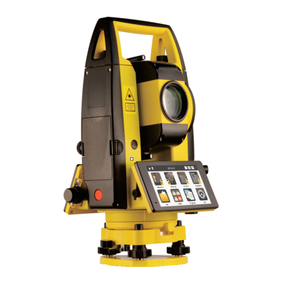
1.2 APPEARANCE a Collimator b Objective Lens c Display Unit d T/P Sensor e Circle Bubble Battery g Horizontal Tangent h Trigger Key j Leveling Screw k RS232 Port Focusing Ring m Eyepiece n Vertical Tangent o Central Mark p Comm Port Tribrach Lock... -
Page 8: Measuring Preparation
1.3 MEASURING PREPARATION Unpacking Storage of Instrument Lay down the case lightly with the cover upward. Cover the cap, place the instrument into the Unlock the case, and take out the instrument. case with the vertical clamp screw and circular vial upwards (lens towards tribrach 1.4 SETTING UP Setup and Levelling the instrument precisely to... - Page 9 D. Leveling the instrument by circular vial. rotating the foot-screw A and B. a) Rotate the foot-screw A and B to move the b) Rotate the instrument in 90º (100gon) around bubble in the circular vial, in which case the its vertical axis and turn the remaining leveling bubble is located on a line perpendicular to a screw or leveling C to center the bubble once...
-
Page 10: Battery Information
Tips: You can also level the instrument precisely adjust by the E-bubble. When the tilt is over ± 3’, the system will enter to E-bubble interface automatically. [X]: The compensating value on X direction [Y]: The compensating value on Y direction [TILT-OFF]: Turn off tilt sensor [TILT-X]: Turn on sensor in X direction only [TILT-XY]: Turn on X&Y sensor in dual directions. - Page 11 Note: Charging a) The operating time depends on the outside The battery must be charged prior to using conditions, such as ambient temperature, before the first time operation. charging time, the cycles of charging, etc. It is recommended for safety to charge the battery The battery LI-39 should be charged only by beforehand or to prepare spare full-charged the official charger NC-III, which packed...
-
Page 12: Dismounting/Mounting The Tribrach
1.6 DISMOUNTING/MOUNTING THE TRIBRACH Dismounting If necessary, the instrument can be dismounted from tribrach. Turn the locking knob about 180° counter-clockwise to disengage anchor jaws, and take off the instrument from tribrach. Mounting Insert three anchor jaws into holes of tribrach and line up the directing stub with the directing slot. -
Page 13: Operation
2. OPERATION 2.1 SYMBOLS V/V% vertical angle/(gradient display) HR/HL horizontal angle right/ left horizontal distance vertical difference slide distance north coordinate east coordinate elevation coordinate m/ft Meter/Feet, distance unit degree/ minute/ second Mil/Gon unit of angle measure prism constant value atmosphere correction value point name... -
Page 14: Function Keys
2.2 FUNCTION KEYS [Quick-Set]: Including the setting of laser pointer, PPM, target, tilt-sensor, measure mode and laser plummet. [Data]: Including raw data, coordinate data, code and graphic data. [Mode]: Including N times, continuous or tracking mode. [Target]: Including Reflector sheet, prism or non-prism mode. -
Page 15: Measurement
3. MEASUREMENT 3.1 ANGLE MEASUREMENT V: Vertical angle HR/HL: Horizontal right or left [0 SET]: Set the current horizontal angle to 0. After that the backsight point should be set again. [HOLD]: Hold the horizontal angle until releasing. [H SET]: Set the horizontal angle by entered a certain value HR: Input the value of horizontal angle [V/%]: Switch the display of angle between... -
Page 16: Distance Measurement
3.2 DISTANCE MEASUREMENT SD: The slide distance. HD: The horizontal distance. VD: The vertical distance. [MEAS]: Measure. [MODE]: Switch the measure mode [S.O]: Enter the page of stake out. [HD]: Input the horizontal distance for stake out point. [VD]: Input the vertical distance for stake out point. -
Page 17: Coordinate Measurement
3.3 COORDINATE MEASUREMENT N: North coordinate. E: East coordinate. Z: Elevation coordinate. [MEAS]: Measure [MODE]: Switch the measure mode [R.HT]: Input the reflector height. [INHT]: Input the instrument height. [STN]: Input the coordinate of station Please redefined the backsight point after station setting. -
Page 18: Station
4. STATION Each coordinate computation relates to the currently set station. Please set the station by known points before surveying and stake out,. 4.1 KNOWN POINT There’re two methods to set the backsight point: one is by the coordinates of the known point, the other is by the angle of the known point. -
Page 19: Station Height
4.2 STATION HEIGHT Calculate the station height by measuring a point with known height. Ht: Input the height of known point, user can selected it from internal memory. VD: The current vertical angle. StnHt(Meas): The measured height of station. StnHt(Current): The current height of station. [MEAS]: Start to measure [SET]: Set the measured result as the STN Ht. -
Page 20: Resection
4.4 RESECTION Note: a) If the angle between the first measurement point and the second one is too small or too large, it will influent the geometrical accuracy of calculation result. So selecting a geometrical The “Resection” function, also known as Free graphic with good structure is important. -
Page 21: Point To Line
Pt: Input the ID of known point. R.Ht: Input the reflector height. HA: The measured result of horizontal angle. VA: The measured result of vertical angle. SD: The measured result of slide distance [ANG.]: Only angle measurement. [ANG&DIST]: Angle & distance measurement. ☞... -
Page 22: Collect
5. COLLECT 5.1 MEASURE POINTS It included not only measure and record, but also the point coding and linking in graphic display. Pt: Input the ID of point. It will add “1” automatically on the point name in each time. Code: Input or select the code. -
Page 23: Distance Offset
5.2 DISTANCE OFFSET Pt: Input the ID of point. Code: Input or call up the code. The distance offset calculates from measurement R.Ht: Reflector height. or coordinates longitudinal, parallel offset and [L][R]: The lateral deviation in left or right height differences of the target point relative to [Fw][Bw]: Difference in length. -
Page 24: Plane Offset
5.3 PLANE OFFSET [Meas]: Measure the point. [Reset]: Re-measure the point. [View]: View the result. Consider that Point P0 is on the edge of a plane, [SAVE]: Save the calculation result. which cannot be measured directly through non- reflector mode. HA: The current horizontal angle. -
Page 25: Column Offset
5.4 COLUMN OFFSET DireA: Collimate the side of column. Column offset is widely used in measuring a DireB: Collimate the other side of column. hidden point that is not directly visible, for Center: Collimate the center and measure. example the center of column as picture shown. [OK]: Angle of Direction A/B has been set. -
Page 26: Mlm
5.5 MLM (TIE DISTANCE) StartPt: Entered or selected a start point HD: The horizontal distance between two points. MLM function is mainly used to compute the HD/ VD: The vertical distance between two points. VD/ SD/ azimuth between two target points. SD: The slide distance between two points. -
Page 27: Line & Extend Point
5.6 LINE & EXTEND POINT HA: The current horizontal angle. The extension function computes extend point VA: The current vertical angle. from the base line, calculate the unknown Pt P1: The slide distance to the first point. coordinate from two known points and the Pt P2: The slide distance to the second point. -
Page 28: Line & Extend Angle
5.7 LINE & EXTEND ANGLE HA: The current horizontal angle. The extension function computes extend point VA: The current vertical angle. from the base line, calculate the unknown Pt P1: The slide distance to the first point. coordinate from two known points and the Pt P2: The slide distance to the second point. -
Page 29: Rem
5.8 REM The points directly above the prism can be VA(the first line): Current vertical angle. determined without a reflector at the target point. dVD: Vertical difference between measured point and target. When you need the information of a target hang R.Ht: Reflector height. -
Page 30: Stake Out
6. STAKE OUT 6.1 POINT STAKE-OUT Setting out the coordinates from memory or manually entered Pt: ID of the stake-out point. R.Ht: Reflector height [LAST]: Select the last stakeout point [NEXT]: Select the next stakeout point. ☞ The menu of Stake-out [SAVE]: Save the current stake-out point [MEAS]: Select the next stakeout point. -
Page 31: Angle & Distance Stake-Out
6.2 ANGLE & DISTANCE STAKE-OUT Stake-out the points by entered the value of angle offset (HA), longitudinal offset (HD) or height offset (Z) 6.3 ALIGNMENT STAKE-OUT Stake-out the points by entered the value of azimuth, longitudinal offset (HD) and height offset (VD) Find further details on “Point Stake-out”... -
Page 32: Line Stake-Out
6.4 LINE STAKE-OUT It will calculate the coordinates of the stake- out point through two known points (St Pt and End Pt) and the offset distance (left or right, forward or backward, up or down) based on the line which is formed by the known points Find further details on “Point Stake-out”... -
Page 33: Cogo
8. COGO 8.1 TRAVERSE Calculate the coordinates of point with a known point, based on the direction and distance offset St Pt: Start point. Input a known point St.Ang: Azimuth of start point Turn: The turning direction of start point. [SAVE]: Save the calculation result [CALC]: Calculate the coordinate 8.2 INVERSE... -
Page 34: Area & Girth
8.3 AREA & GIRTH Calculate the area and perimeter of known points. The added points will be displayed on the list [ADD] or [Insert]: Add or insert points from the memory. Click to switch between add and insert. [Del]: Delete a chosen data on the list [Calc]: Calculate 8.4 POINT-LINE INVERSE ☞... -
Page 35: Intersection-2 Points
Defined a line between two points, P1 and P2, the offset point P3 is perpendicular to this line. The system will calculate the HD from start point P1 to orthogonal point P4, and from offset point P3 to orthogonal point P4 ☞... - Page 36 ☞ the intersection by azimuth and distance ☞ the intersection result in graphic. Calculate the intersection by Azimuth Calculate the intersection by Distance...
-
Page 37: Intersection-4 Points
8.6 INTERSECTION-4 POINTS Calculate intersection point of two lines which are formed by four points St P1/End P1: The start/end point of Line 1 St P2/End P2: The start/end point of Line 2 [CALC]: Calculate the coordinate of the intersection point. [SAVE]: Save the coordinate 8.7 VOLUME The system will create a triangulation network... -
Page 38: Road
☞ the calculation result of volume. ☞ the graphic result of volume. 9. ROAD Road Program in A1 system, calculate the target as a composite curve which might including the elements of straight line, transition curve and circular curve. The system will stake- out the designed road based on the pile number and deviation value ☞... -
Page 39: Road Select
9.1 ROAD SELECT Select a road as the current job. Each road included two parts, Press [+] to create a new job. You can also edit or delete the current job in job list ☞ job list 9.2 H-ALIGNMENT The horizontal alignment including the elements of start point, straight line, circular curve and transition curve. - Page 40 St Mile: entered the mile of start point N: North coordinate of start point E: East coordinate of start point Azimuth: Azimuth of start point ☞ Input the parameter of start point Length: entered the length of straight line. the value should > 0. ☞...
- Page 41 R: entered the radius of curve. The positive value means the road is turning right, the negative value means left. Arc: the length of curve, the value should > 0. ☞ Input the parameter of circular curve Para: Input the parameter, the positive value means turning left, negative value means turning right.
-
Page 42: V-Alignment
☞ Graphic display of the horizontal alignment. ☞ Element list of horizontal alignment, click each item to edit or delete the data. 9.3 V-ALIGNMENT The vertical alignment is composed by the intersection points which including pile number, elevation and length of the curve. The length of curve, for start and end point must be zero. -
Page 43: Road Stake-Out
[ADD]: Add a new element of vertical alignment. Pile: The pile ID of changing point Ht: The height of changing point Front V%: The vertical slope between current point to the last point. Back V%: The vertical slope between current point to the next point. -
Page 44: Set
St Mile: The start position of stake-out Step: The increased or decreased mile in each step. L/R: The left or right offset from the middle line of the road. Up/Dn: The elevation offset of the design point to the middle line. [NEXT]: Go for next step (stake-out). -
Page 45: Angle
10.2 ANGLE V0: Set horizontal zero or vertical zero. Tilt-comp: On or off the tilt compensator. Press the information button on the right corner to set the current setting as default. The new job will follow the same settings. 10.3 DISTANCE Para Scale: Set the scale factor of measurement. - Page 46 T-P Set T-P Sensor: On/off the temperature & pressure sensor. T-P Auto: On/off the T-P auto correction Temp: Set the current temperature. Pres: Set the current pressure. PPM: Set the atmosphere correction value. Mode Select: N times, continuous or tracking. Average: calculate the average value N times: Set the measure times, maximum 20.
-
Page 47: Coordinate
10.4 COORDINATE Order: the order of coordinate display. By N-E-Z or E-N-Z. HL/HR: Set whether the coordinate value is relative to instrument’s HL or HR, if not, the measurement results on both left face and right face are the same. 10.5 COMMUNICATION Comm: On or off the comm port. -
Page 48: Adjustment
10.6 ADJUSTMENT Constant K: Set the constant K of prism or non- prism mode. Vertical 0: The adjustment of vertical difference (the so-called i-angle). This item must be adjusted when finished compensator crosshair adjustment. TiltComp: The adjustment of electronic tilt-sensor, also called E-bubble. -
Page 49: Initialize
10.8 INITIALIZE Initialize: Initialize the parameter/ settings back to the factory mode. 10.9 ABOUT SW Info: View the software information, including the software version, model name, SN and device ID. Also you can check the version of mainboard, EDM, compensator and T-P sensor. -
Page 50: Data
11. DATA 11.1 RAW DATA View the raw data. For further data format, please check the Appendix in the last page. Clear the data list, import or export the raw data. Search the point from the data list. 11.2 COORDINATE DATA View the coordinate data. -
Page 51: Code Data
11.3 CODE DATA View the code data. Click the code in once to edit or delete the data. Clear the data list, import or export the raw data. Search the point from the data list. 11.4 GRAPHIC DATA View the graphic data. Sort and filter the points. -
Page 52: Data Import
11.5 DATA IMPORT Click [Import] and [FILE] to select the file from internal memory or flash disk. Choose the data type (Coordinate/ Code data) and format (the display order of point name, code, N, E, Z) you want, then click [IMP.] for import. -
Page 53: Data Export
11.6 DATA EXPORT Click [Export] to choose the location (RAM/ Comm or U-disk), data type (Coordinate/ Code/ Raw Data) and the format you want, then click [EXP.] for export. Entered the name and save the file. A1 is available to transfer the data by Bluetooth. Check [Settings], [Bluetooth] in Android system to pair the devices. -
Page 54: Quick Set
12. QUICK-SET ★ Including the quick set of laser pointer, PPM, target, tilt-sensor, measure mode and laser plummet. Press ★ or slide the finger from the left side of screen to activate the page of quick-set. 12.1 PPM SET Temp: Temperature of current job. Pres: Pressure of current job. -
Page 55: Target
12.2 TARGET Reflec.: Set the target to reflector sheet Prism: Set the target to prism Non-P: Set the target to non-prism 12.3 TILT SENSOR Tilt-XY: On or off the tilt-sensor. It can be selected among Tilt-X (single-axis), Tilt- XY (dual-axis) or Tilt-Off. L-P ON: on or off the laser plummet. -
Page 56: Measure Mode
12.4 MEASURE MODE N Times.: Set the measure times as N, and decide whether to calculate the average value or not. Continu.: Continuous mode. Tracking: Tracking mode. The accuracy will lower than the other mode, with faster speed. 12.5 LASER PLUMMET Adjust the illumination level of laser plummet from level 1-5. -
Page 57: Inspection & Adjustment
13. INSPECTION & ADJUSTMENT The instrument has passed the procedure of inspection and adjustment before releasing to the market, which ensures that it meets quality requirement. However, after long periods of transportation or the changeable environment, some influences may occur to the internal structure. Therefore, before the instrument is used for the first time, user should check and adjust the functions we introduced in this session to ensure the precision of the job. -
Page 58: Circular Vial
13.2 CIRCULAR VIAL Inspection Adjustment It is not necessary to adjust the circular vial, If the bubble of the circular vial is not in the except the bubble is not in the center after the center, adjust the bubble to the center by using adjustment of plate vial. -
Page 59: Reticle Unit
13.4 RETICLE UNIT Inspection Adjustment 1. Sight object A after leveling the equipment, 1. Remove the eyepiece cover to expose the lock the horizontal and vertical tangent unit and four reticle adjusting screws, as picture shown. make sure that target A is in the center of cross- 2. -
Page 60: Perpendicularity Between Sight Of View & Horizontal Axis (2C)
13.5 PERPENDICULARITY BETWEEN SIGHT OF VIEW & HORIZONTAL AXIS (2C) Inspection Adjustment 1. Set object A at a far distance at the same 1.Use the horizontal tangent screw to adjust the height as the instrument, leveling the instrument reading of HA. and turn on the power (eg. -
Page 61: Compensation Of Vertical Index Difference
13.6 COMPENSATION OF VERTICAL INDEX DIFFERENCE Inspection of compensation. When rotate the vertical 1. After leveling the instrument, make the EDM tangent unit in opposite direction back to the parallel with the line connecting the center of original place, the instrument will show the the instrument to any one of the screws. - Page 62 Inspection Adjustment 1. After leveling the instrument, collimate at any 1. Aim at target A in same height with the target A in HL. Record the value as L. instrument in HL. 2. Rotate the EDM and aim at the target A in HR. 2.
-
Page 63: Constant K
13.8 CONSTANT K The Instrument constant has been checked and adjusted in the factory, and K=0. It seldom changes and it is suggested to check once or twice in a year. Inspection adjusted according to the inspection value. 1. Mount and level the instrument on Point A on Adjustment flat ground. -
Page 64: Coincidence Between Sight Of View And Emitting Axis
13.9 COINCIDENCE BETWEEN SIGHT OF VIEW AND EMITTING AXIS Inspection Adjustment 1. Set the reflector 50m away from the instrument. If there is a huge deviation between the sight of Aim at the center of prism precisely. view and emitting axis, please send the 2. -
Page 65: Specification
14. SPECIFICATIONS 14.1 DISTANCE MEASUREMENT Model A1 1” A1 2” Prism N Times < 1.2s < 1.2s Prism Standard Single: 4km, Triple: 5km Continuous < 0.7s < 0.5s Enhanced Single: 5km, Triple: 6km Tracking < 0.3s < 0.25s Sheet 1.2km Prism N Times <... - Page 66 14.2 ANGLE MEASUREMENT Plate Vial 30”/2mm Circular Vial 8’/2mm Accuracy 1”/2” 2” System Dual-axis Minimum Reading 0.1”/1” 1” ± 3’ Compensate Range Measure Method Absolute Encoding Resolution Ratio 1” Diameter of Disk 79mm Laser Level Level II, red laser Angle Unit Degree, Gon, Mil Accuracy 1.5mm (InsHt 1.5m)
-
Page 67: Error Code
15. ERROR CODE 14.4 ANDROID SYSTEM CODE DESCRIPTION SOLUTION MEMORY 16GB ERROR Problems in angle Restart equipment. 01-06 measurement If the error code still CPU Version MT6735 system remains, please FEATURES Display Unit 5inch, 118*65mm ERROR contact your Problems Input Method Touch screen 31-36 authorized agency... -
Page 68: Safety Guide
16. SAFETY GUIDE 16.1 INTERNAL DISTANCE METER (VISIBLE LASER) Warning Regulation) The total Station is equipped with an EDM of Class 3A/III a laser product: It is harmful to Laser Class 3A/III a and it is verified by these observe the laser beam continuously. Users labels as follows: should avoid staring at the laser directly. - Page 69 Warning that might bring dangers (according When the laser beam emits on prism, mirror, IEC60825-1:2001) metal surface, window, it might be dangerous to look directly at the reflecting light. There are explanations of some principle points Prevention of related standard as follows: Do not stare at the direction which the laser Class 3R laser product is used in outdoors and beam is reflected.
-
Page 70: Laser Plummet
must stop the laser beam in time. * Harmful distance suggests that the maximum d. The optical path of the laser beam should distance from the start point of the laser beam to be set higher or lower than the line of sight. the point which the laser beam is weakened to e. -
Page 71: Appendix - Data Format
Class II laser product is in accordance with the Class 2/II Laser Product: following standard: Do not stare at the laser beam or point it at FDA21CFR ch.1 § 1040:1998 (U.S. Department of others. Users should prevent the laser beam and Health and Human Services, Code of Federal the strong reflecting light from impinging into Regulations) - Page 72 轴] Coordinates Data The data in below formats can be transferred to Vertical Alignment the computer. mile, elevation, length 1. Pt, N, E, Z, code 单轴 2. Pt, E, N, Z, code DXF File 3. Pt, code, N, E, Z Refer to Standard R12.
Need help?
Do you have a question about the A1 Series and is the answer not in the manual?
Questions and answers