
Related Manuals for South N6 Series


Summary of Contents for South N6 Series
- Page 1 Operation Manual N6 Series Electronic Total Station SOUTH SURVEYING &MAPPING INSTRUMENT CO., LTD ...
- Page 2 INTRODUCTION Congratulations on purchasing total station N6 series! This manual is applicable for total station N6 series. N6 series is equipped with visible laser emitter and reflectorless EDM. Sections with“ ” will be just application for N6 series. Read this manual carefully before use. Declaration: South reserves the right of not notifying users in advance about any technical modification. ...
-
Page 3: Table Of Contents
INDEX FEATURES: ..........................1 CAUTIONS: ..........................2 BATTERY NOTIFICATION ......................3 SAFETY GUIDE ..........................4 1. NOMENCLATURE AND FUNCTIONS ..................6 1.1 NOMENCLATURE ........................ 6 1.2 FUNCTIONS OF KEYS AND INFORMATION DISPLAYED ........... 8 1.3 FUNCTIONAL KEYS ...................... 1 0 1.4 STAR (★) KEY MODE ...................... 1 3 2. INITIAL SETTINGS ........................ 14 2.1 POWER ON/OFF ........................ 1 4 2.2 SETTING OF TILT CORRECTION ON VERTICAL AND HORIZONTAL ANGLES .... 1 4 2.3 SETTNG DISTANCE MEASUREMENT MODE .............. 1 7 2.4 SETTING CONSTANT OF REFLECTING PRISM .............. ... - Page 4 3.4 REFLECTING PRISM ...................... 3 3 3.5 MOUNTING AND DISMOUNTING INSTRUMENT FROM TRIBRACH ...... 3 4 3.6 EYEPIECE ADJUSTMENT AND COLLIMATING OBJECT ........... 3 4 3.7 METHOD OF INPUTTING ALPHARNUMERIC CHARACTERS ......... 3 5 4. ANGLE MEASUREMENT ..................... 38 4.1 MEASURING HORIZONTAL AND VERTICAL ANGLE ............ 3 8 4.2 SHIFT THE HORIZONTAL ANGLE (RIGHT/LEFT) ............... 3 9 4.3 SETTING HORIZONTAL ANGLE .................. 4 0 4.3.1 Setting by [Hold] ...................... 4 0 4.3.2 Setting by Input Through Keyboard ................ 4 1 4.4 SHIFT BETWEEN V ANGLE AND V% ................ ...
- Page 5 7. DATA COLLECTION ...................... 69 7.1 OPERATION PROCEDURE .................... 7 0 7.2 PREPARATION ........................ 7 1 7.2.1 Selecting A File For Data Collection ................ 7 1 7.2.2 Selecting A Coordinate File (For Shorage) .............. 7 1 7.2.3 Selecting A Coordinate File (For Use) ............... 72 7.3 OCCUPIED POINT AND BACKSIGHT POINT .............. 7 3 7.3.1 Example for setting the Occupied Point .............. 7 4 7.3.2 Example for setting the azimuth ................ 76 7.4 MEASURING AND SAVING THE DATA ................ 7 8 7.4.1 Searching the recorded data .................. 8 0 7.4.2 Entering PCODE/ID ..................... 8 1 7.4.3 Entering PCODE by Using PCODE library .............. 8 2 7.5 DATA COLLECT OFFSET MEASUREMENT MODE ............ ...
- Page 6 8.4.2 Resection Method .................... 1 09 9. MEASUREMENT PROGRAM MODE ................ 114 9.1 REMOTE HEIGHT MEASUREMENT (REM) .............. 1 14 9.2 TRAVERSE………………………………………………………………………………………………………117 9.3 SETTING Z COORDINATE OF OCCUPIED POINT ............ 1 19 9.4 COGO…………………………………………………………………………………………………………….123 9.4.1 Intersection………………………………………………………………………………………………123 9.4.2 Intersection‐4……………………………………………………………………………………………124 9.4.3 Inverse……………………………………………………………………………………………………..126 9.4.4 MLM………………………………………………………………………………………………………..127 9.4.5 Radiation………………………………………………………………………………………………….132 9.4.6 Area Measurement .................... 1 33 9.4.1 Area calculation from Coordinate data file ............ 1 33 9.4.2 Area Calculation from Measured Data ............... 1 35 9.4.3 to Change the Display Unit .................. 1 35 9.5 MEASUREMENT FROM POINT TO LINE ................ 1 36 9.6 ROAD .......................... ...
- Page 7 11. MEMORY MANAGEMENT ..................... 168 11.1 FILE MAINTAIN ....................... 1 68 11.1.1 Check the Memory and Format the Disk ............ 1 68 11.1.2 Create a New File .................... 1 70 11.1.3 Renaming a File ...................... 1 71 11.1.4 Delete file ........................ 1 72 11.1.5 Edit Measured Data in Search Mode .............. 1 73 11.2 DATA IMPORT ........................ 1 75 11.2.1 User‐defined Receive/Send Format .............. 1 76 11.3 FILE OUTPUT ........................ 1 77 11.4 DATA TRANSFER ...................... 1 78 11.4.1 Setting Parameter of Data Communication ............ 1 79 11.4.2 Send data (RS232 Mode) ...
- Page 8 【APPENDIX‐B】 CALCULATE ROAD ALIGNMENT ............ 206 1. ROAD ALIGNMENT ELEMENTS .................. 2 06 2. CALCULATION ROAD ALIGNMENT ELEMENTS .............. 2 08 【APPENDIX-C】 ....................... 215 1. DATA OUTPUT FORMAT OF NTS SERIES TOTAL STATION .......... 2 15 2. STEERING INSTRUCTION AND FORMAT ................. 2 17 3. REAL‐TIME COMMUNICATION PROCESS BETWEEN SOUTH TOTAL STATION AND COMPUTER .......................... 2 18 Attachment 1: ........................ 221 In STAR (★) KEY MODE ...................... 2 21 ...
-
Page 9: Features
FEATURES: Excellent Functionality SOUTH total station N6 is embedded with various outstanding surveying programs, coupled with functions of data storing and parameter setting, which can be widely applied in various kinds of professional and construction survey. 2. Absolute Encoding Disk With absolute encoding disk, you can start your work directly as the instrument is powered on. Azimuth angle will be saved even if the power is off incidentally in the job. SD card Function SD card provides huge memory, fast speed of data transferring, incredibly flexibility and reliable safety. Saving various data of job into the SD card, you can easily read it just by ... -
Page 10: Cautions
surveying programs, such as remote height measurement, offset measurement, remote distance measurement, stake out, resection, area calculation, road design and stake out, etc., which are sufficient to meet the needs of professional measurement and surveying measurement. CAUTIONS 1. Do not collimate the objective lens direct to sunlight without a filter. 2. Do not store the instrument in high and low temperature to avoid the sudden or great change of temperature. 3. When the instrument is not in use, place it in the case and avoid shock, dust and humidity. 4. If there is great difference between the temperature in work site and that in store place, you should leave the instrument in the case till it adapts to the temperature of environment. 5. If the instrument has not been used for a long time, you should remove the battery for separate storage. The battery should be charged once a month. 6. When transporting the instrument should be placed in its carrying case, it is recommended that cushioned material should be used around the case for support. ... -
Page 11: Battery Notification
BATTERY NOTIFICATION 1 .Battery should be recharged only with the charger NC‐20 going with the instrument 2 .Battery Recharging Cautions: The charger has built‐in circuitry for protection from overcharging. However, do not leave the charger ... -
Page 12: Safety Guide
SAFETY GUIDE Warning: The total station is equipped with an EDM of a laser grade of 3R/Ⅲa. It is verified by the following labels. CAUTION LASER RADIATION‐DO NOT STARE INTO BEAM 620‐690nm CLASS Ⅲ LASER PRODUCT On the vertical tangent screw sticks an indication label “CLASS III LASER PRODUCT”. A similar label is stick on the opposite side. This product is classified as Class 3R laser product, which accords to the following standards. IEC60825‐1:2001 “SAFETY OF LASER PRODUCTS”. Class 3R/Ⅲ a laser product: It is harmful to observe laser beam continuously. User should avoid sighting the laser at the eyes. It can reach 5 times the emitting limit of Class2/II with a wavelength of 400mm‐700mm. Warning: Continuously looking straight at the laser beam is harmful. Prevention: Do not stare at the laser beam, or point the laser beam to others’ eyes. Reflected laser beam is a valid measurement to the instrument. Warning: When the laser beam emits on prism, mirror, metal surface, window, etc., it is dangerous to look straight at the reflex. Prevention: Do not stare at the object which reflects the laser beam. When the laser is switched on (under EDM mode), do not look at it on the optical path or near the prism. It is only allowed to observe the prism with the telescope of total station. Warning: Improper operation on laser instrument of Class 3R will bring dangers. ... - Page 13 control within the distance that would incur dangers (according to IEC60825‐1:2001). The following shows the explanation related to the key sections of the Standard. Laser instrument of Class 3R is applicable outdoors and in construction field (measurement, defining lines, leveling). a) Only those persons who are trained with related course and authenticated are allowed to install, adjust, and operate this kind of laser instrument. b) Stand related warning symbols in the scale of use. c) Prevent any person to look straight at or use optical instrument to observe the laser beam. d) To prevent the harm caused by laser, block the laser beam at the end of the working route. When the laser beam exceeds the limit area (harmful distance*) and when there are motivating persons, stopping the laser beam is a must. e) The optical path of the laser should be set higher or lower than the line of sight. f) When the laser instrument is not in use, take care of it properly. The person who is not authenticated is not allowed to use. ...
-
Page 14: Nomenclature And Functions
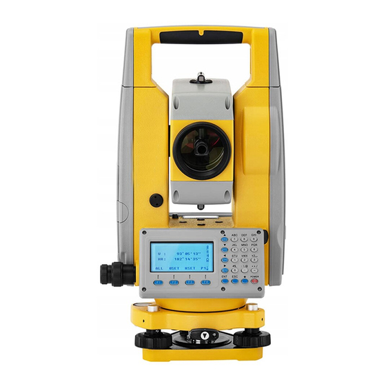
1. NOMENCLATURE AND FUNCTIONS 1.1 NOMENCLATURE Optical Lens Collimator Plate Vial Battery Lock Display Unit Plummet Horizontal Tangent Unit Tribrach Lock Leveling Screw ... - Page 15 Eyepiece Vertical Tangent Unit Battery Data Port Circle Vial Base ...
-
Page 16: Functions Of Keys And Information Displayed
1.2 FUNCTIONS OF KEYS AND INFORMATION DISPLAYED Dist Angle Coordinate (shift down) (shift up) (shift left) Numeric Keyboard Power Switch Star Key MENU F1-F4 (shift right) KEYS: Key Name ... - Page 17 F1~F4 Soft Keys Functions corresponding to information displayed. Number Keys Input numbers or characters or select items of the 0~9 menu. Input symbols, decimal point, ± signs. Symbol Keys ∙~ ‐ Star Key Applicable for some certain common functions. Symbols Displayed: Symbol Displayed Meaning V% vertical angle (slope) HR horizontal angle(right) HL horizontal angle(left) HD horizontal distance ...
-
Page 18: Functional Keys
1.3 FUNCTIONAL KEYS ANGLE MEASUREMENT MODE (3 interface menus) V ... - Page 19 DISTANCE MEASUREMENT MODE (2 interface menus) V : 90°10′20″ HR: 122°09′30″ SD* [F.S] << HD: ...
- Page 20 COORDINATES MEASUREMENT MODE (3 interface menus) Page Soft Key Display Function Start coordinates measurement, and save the results in respective job. (Measurement files and coordinates files are F1 ALL selected in DATA COLLECT menu.) Page 1 ...
- Page 21 1.4 STAR ( ) ★ KEY MODE Press ★, the screen will show: Reflector [Sheet]→ Plummet : 2 ← Contrast: 2 ↑ CrosHair: 4 ↓ ...
-
Page 22: Initial Settings
2. INITIAL SETTINGS 2.1 POWER ON/OFF Operation Operation Procedure Display Model :N6 Number: S00001 Turn on the power, the screen will show: Ver. :2016.04.26 Insert a SD card, the instrument will start SD Card Connected! to detect the SD card. Press [POWER] V : 90°10′20″ HR: ... - Page 23 ● Total station N6 Series is able to automatically correct the horizontal and vertical angle readings deviations which are caused by tilt of instrument’s vertical axis on X and Y direction. ● Total station N6 Series provide 3 tilt correction modes: disable tilt sensor, X‐ON (single axis) and XYON (dual axis). Dual axis compensation: Correct the errors of horizontal angle caused by the index error of vertical angle and tilt of vertical axis. When it exceeds the limit, the system will indicate “Tilt Over”. User should level the instrument manually. Single axis compensation: Correct the index error of vertical angle. When it exceeds the correction limit of vertical angle, the system will show notice. Disable tilt sensor: Close the tilt compensator. ● If the instrument operates under a unstable status or windy days, the vertical angle displays unstably. In such circumstances, the tilt sensor should be disabled, so that it will avoid the instrument from displaying error messages as well as abortion of measurement caused by the tilt sensor exceeding the correction limit. ...
- Page 24 Tilt Sensor: [ XYON ] ③ When the tilt of instrument exceeds the correction range, it needs leveling manually. Follow the steps described in “3.2 ...
-
Page 25: Settng Distance Measurement Mode
2.3 SETTNG DISTANCE MEASUREMENT MODE Total station NTS360R Series can adopt visible laser distance measurement and invisible IR distance measurement. Prism, non‐prism and reflecting sheet are selectable as reflector. User can set a mode according to the job requirement. Please refer to “13. TECHNICAL PARAMETER” about the parameters of various kinds of reflectors. Operation Procedure Operation Display Reflector [Sheet]→ Plummet : 2 ← Contrast: 2 ↑ ① ... -
Page 26: Setting Constant Of Reflecting Prism
2.4 SETTING CONSTANT OF REFLECTING PRISM When using prism as reflector, it is required to set the prism constant before measurement. As the prism constant is set, such constant will be maintained even after power off. Step Operation Operation Procedure Display TEMP. : 20.0 ℃ PRESS. : 1013.0 hpa PRISM : 0.0 mm [★] ... -
Page 27: Reflecting Signal
2.5 REFLECTING SIGNAL Reflecting signal function displays the intensity of EDM’s reflecting signal. It helps user to collimate the target in tough conditions. Once receiving the reflecting light from the prism, the instrument will buzz. In circumstance that target is not easy to be found, this function will help you easily collimate the target. Step Operation Operation Procedure Display Reflector [Sheet]→ Plummet : 2 ← Contrast: 2 ↑ 1 [★] Enter to Star key mode. ... -
Page 28: Setting Atmospheric Corrction
2.6 SETTING ATMOSPHERIC CORRCTION When during distance measurement, the result may be affected by atmostpheric condition. To overcome the affection of the atmospheric condition, it is necessary to use make correction through atomospheric correction constant during distance measurement. Temperature: the temperature of the surrounding air. Pressure: the atmospheric pressure surrounding the inistrument. PPM: the atmospheric correction calculated and estimated. ●Standard atmospheric condition of total station NTS series (i.e. the atmospheric condition when the atmospheric correction value is 0): Pressure: 1013hPa Temperature: 20°C ● Calculation of atmospheric correction: ΔS =278.44 – 0.294922 P / ( 1 + 0.003661T )(ppm) In the formula: ΔS: correction coefficient (unit: ppm) P: pressure (unit: hPa) When the unit of atmospheric pressure is mmHg, follow this formula: ... -
Page 29: The Atmospheric Correction Value Directly
2.6.1 Setting the Atmospheric Correction Value Directly Measure the temperature and press, then calculate the atmospheric correction value (PPM) through the atmospheric correction grap or the formula. Step Operation Operation Procedure Display TEMP. : 20.0 ℃ PRESS. : 1013.0 hpa PRISM : 0.0 mm Enter to Star key mode, press ... - Page 30 Step Operation Procedure Display TEMP. : 20.0 ℃ PRESS. : 1013.0 hpa PRISM : 0.0 mm 1 [★] Enter to Star key mode. PPM : 0.0 ppm SIGNAL : ...
-
Page 31: Correction On Atmospheric Refraction Error And Earth Curvature
2.7 CORRECTION ON ATMOSPHERIC REFRACTION ERROR AND EARTH CURVATURE During horizontal distance measurement and height difference measurement, the instrumentcna correct the atomospheric refraction error and earth curvature automatically. Formular of correction on atomospheric refraction error and earth curvature: Hrozizontal distance after correction: D=S * [cosα+ sinα* S * cosα (K‐2) / 2Re] Vertical differecen after correction: H= S * [sinα + cosα* S * cosα (1‐K) / 2Re] If you do not correct the atomospheric refraction error and earth curvature, the fomular for HD and VD: D=S∙cosα H=S∙sinα In the formula ... - Page 32 Procedure Operation Display MENU 1/2 1﹒DATA COLLECT ① Press [MENU] to enter to 1/2 of main [MENU] 2﹒LAYOUT 3﹒MEMORY MGR. ...
-
Page 33: Setting Auto Power Off
2.9 SETTING AUTO POWER OFF When no key is pressed or no suvey is implemented in 30 minutes, the instrument will be switched off automatically. Procedure Operation Display MENU 1/2 ① Press [MENU] to enter to 1/2 of the 1﹒DATA COLLECT [MENU] main menu, and press [5] 2﹒LAYOUT [5] ... -
Page 34: Setting Instrument Constant
2.10 SETTING INSTRUMENT CONSTANT Follow the method described in 12.9 “ADDICTIVE CONSTANT OF THE INSTRUMENT” to calculate the addictive constant of the instrument. Setting of instrument constant is stated below. Procedure Operation Diplay MENU 2/2 1. ADJUSTMENT [MENU] ① Press [MENU] to enter to the 2. INST.CONSTANT [F4] ... -
Page 35: Select A Code File
5.Grid Factor P↓ ② When it displays the interface of Select code file FILE:SOUTH selecting a code file, enter the file name of the code you want to call up. ※1) BACK LIST ALPH ENT ... -
Page 36: Hardware
2.12 HARDWARE Procedure Operation Display MENU 2/2 1. ADJUSTMENT [MENU] ① Press [MENU] to enter to the 2. INST. CONSTANT [F4] ... -
Page 37: Preparation For Measurement
3. PREPARATION FOR MEASUREMENT 3.1 UNPACKING AND STORE OF INSTRUMENT ∙ Unpacking of instrument Place the case lightly with the cover upward, and unlock the case, take out the instrument. ∙ Storage of instrument Cover the telescope cap, place the instrument into the case with the vertical clamp screw and circular vial upwards (Objective lens towards tribrach), and slightly tighten the vertical clamp screw and lock the case. 3.2 INSTRUMENT SETUP Mount the instrument to the tripod. Level and center the instrument precisely to ensure the best performance. Operation Reference: 1. Leveling and Centering the Instrument by plumb bob 1) Setting up the tripod ① First of all, extend the extension legs to suitable length, make the tripod head parallel to the ground and tighten the screws. ② Make the centre of the tripod and the occupied point approximately on the same plumb line. - Page 38 ② Turn the leveling screw C to move the bubble to the center of the circular vial. 4) Precisely leveling by using the plate vial ①...
- Page 39 2. Centering by using the optical plummet 1) Set tripod Lift tripod to suitable height, ensure equal length of three legs, spread and make tripod head parallel to the ground, and place it right above the measurement station point. Prop up tripod on the ground and fix one leg. 2) Install instrument and collimate the point Set instrument carefully on tripod, tighten the central connecting screw and adjust optical plummet to make the reticle distinctly. Hold the other two unfixed legs with both hands and adjust position of these two legs through observation of optical plummet. As it approximately aims at the station point, make all three legs fixed on the ground. Adjust three leg screws of the instrument to make optical plummet collimate precisely to the station point. 3) Use circular vial to roughly level the instrument. ...
-
Page 40: Loading, Unloading, Charging The Battery And Itsinformation
3.3 LOADING, UNLOADING, CHARGING THE BATTERY AND ITSINFORMATION V : 90°10′20″ HR: 122°09′30″ SD* [F.S] << HD: ... -
Page 41: Reflecting Prism
Charging the Battery Charge the battery with the appropriative charger (NC‐20A). Before charging, link the charger with the electrical outlet first. Unload the battery from the instrument and connect the charger plug with the charging outlet of the battery. When the indicator light of the charger is orange, it means the battery is being charged. When the light is green, it means the battery is fully charged, please pull out the plug. Cautions for Charging ▲The charger has built‐in circuitry for protection from overcharging. However, do not leave the charger plugged into the power outlet after recharging is completed. ▲ Be sure to recharge the battery at a temperatu re of 0°~±45°C, recharging may be abnormal beyond the specified temperature range . ▲ When the indicator lamp does not light after connecting the battery and charger, either the battery or the charger may be damaged. Please connect professionals for repairing. Cautions for Storage: ▲Rechargeable battery can be repeatedly recharged 300 to 500 times. Complete discharge of the ... -
Page 42: Mounting And Dismounting Instrument From Tribrach
3.5 MOUNTING AND DISMOUNTING INSTRUMENT FROM TRIBRACH Dismounting If necessary, the instrument (including reflector prisms with the same tribrach) can be dismounted from tribrach. Loosen the tribrach locking screw in the locking knob with a screwdriver. Turn the locking knob about 180° counter‐clockwise to disengage anchor jaws, and take off the instrument from tribrach. Mounting Insert three anchor jaws into holes in tribrach and line up the directing stub with the directing slot. Turn the locking knob about 180°clockwise and tighten the locking screw with a screwdriver. 3.6 EYEPIECE ADJUSTMENT AND COLLIMATING OBJECT ( ) Method of Collimating Object for reference ① Sight the Telescope to bright place and rotate the eyepiece tube to make the reticle clear. ... - Page 43 METHOD INPUTTING ALPHARNUMERIC CHARACTERS Total station N6 Series is equipped with alphanumeric keyboards. User can input number and characters during operation. * Inputting Numbers [Example 1] Input the instrument height in Data Collect mode. The arrowhead points to the item which needs to be input. Press [▲] [▼] to move up or down the arrowhead. OCC.PT INPUT OCC.PT → 1 PCODE: INS.HT: ...
- Page 44 *Inputting Angle [Example 2] Input the angle 90°10’20”. H ANGLE SET HR: 90°10′20″ BACK ENT ...
- Page 45 OCC.PT INPUT OCC.PT : 1 PCODE→ SOUTH1 INS.HT: 0.000 m INPUT ...
-
Page 46: Angle Measurement
4. ANGLE MEASUREMENT 4.1 MEASURING HORIZONTAL AND VERTICAL ANGLE Make sure it is in angle measurement mode. Procedure Operation Display V : 82°09′30″ HR : 90°09′30″ ① Collimate the first target A. Collimate A ALL ... -
Page 47: Shift The Horizontal Angle (Right/Left)
4.2 SHIFT THE HORIZONTAL ANGLE (RIGHT/LEFT) Make sure it is under angle measurement mode. Procedure Operation Display V : 122°09′30″ HR: 52°44′10.1″ ① Press [F4] (↓) twice to turn ALL OSET HSET P1↓ [F4] x 2 ... -
Page 48: Setting Horizontal Angle
4.3 SETTING HORIZONTAL ANGLE 4.3.1 Setting by [HOLD] Make sure it is under angle measurement mode. Procedure Operation Display V : 122°09′30″ ① Rotate the lens to the HR: 90°09′30″ horizontal angle which is to Display the be defined by horizontal angle ALL OSET HSET P1↓ ... - Page 49 4.3.2 Setting by Inputting through the Keyboard Make sure it is under angle measurement mode. Procedure Operation Display V : 122°09′30″ HR: 90°09′30″ ⑥ Collimate the target point Collimate and press [F3] (HSET). [F3] ALL OSET HSET P1↓ ...
-
Page 50: Shift Between V Angle And
4.4 SHIFT BETWEEN V ANGLE AND V% Make sure it is under angle measurement mode. Procedure Operation Display V : 90°10′20″ HR: 120°09′30″ ①... - Page 51 Procedure Operation Display V : 90°10′20″ HR: 120°09′30″ ① Press [F4] (↓) to turn to P2. [F4] ALL 0SET HSET P1↓ HOLD REP. V% P2↓ Rep‐Angle Count ...
- Page 52 Rep‐Angle Count [ 2] Ht: 240°40′00″ ⑦ Collimate B again and press Collimate B Hm: 120°20′00″ HR : 120°18′00″ [F4] (HOLD). [F4] OSET ...
-
Page 53: Horizontal Angle 90° Buzzer
4.6 HORIZONTAL ANGLE 90° BUZZER When the horizontal angle reaches the range of 00° (90°, 180° or 270°)±4°30′, the buzzer will be activated. This setting will not be maintained after power‐off. Procedure Operation Display V : 90°10′20″ HR: 170°30′20″ ① Press [F4] (↓) twice to enter [F4] x 2 ALL 0SET HSET P1↓ to P3. ... -
Page 54: Shift Between Azimuth And Vertical Angle
4.7 SHIFT BETWEEN AZIMUTH AND VERTICAL ANGLE Procedure Operation Display V : 20°30′24.8″ HR: 170°30′20″ ① Press [F4] (↓) twice to turn [F4] x 2 ALL 0SET HSET P1↓ to P3. ... -
Page 55: Distance Measurement
5. DISTANCE MEASUREMENT User should avoid measuring distance to targets with high reflectivity (e.g. traffic light) neither in IR distance measurement mode nor in laser reflectorless distance mode, otherwise the measured distance is incorrect or inaccurate. When pressing Meas, the total station will measure the distance between the instrument to the target. During distance measurement, if there’re passers‐by, cars, animals or shaking branches block the light path, some light beams may be refected back to the instrument, which will lead a fake result of measurement. Under the mode of reflectorless and reflecting sheet, user should avoid the light path being blocked by other objects. Reflectorless Distance Measurement ● Make sure the laser beam is not reflected by any reflecting objects nearby. ● When star ting distance measurement, EDM will measure the distance to the target on the light path. If there’re passing objects (like cars, rain, snow or frog), EDM will measure the distance to the nearest object. ● When measuring a longer distance, the laser bea m may deviate from the collimation line, which will affect the accuracy. This is because the emitting point of laser beam may not coincide the point which is collimated by the crosshair. Thus, users are recommended to adjust the instrument precisely to ensure the laser beam is consistent with the collimation line. (Refer to “12.11 REFLECTORLESS DISTANCE MEASUREMENT”) ... - Page 56 VD: 36.551m ﹥REC.? [NO] [YES] press [F4] (YES) to return to POINT:1 distance measurement mode. PCODE:SOUTH [F1] V : 90°10′20″ After the measurement of one [F4] ...
-
Page 57: Setting Measurement Mode
※ 2) Units of distance: “m” (meter), “ft” (feet), “fi”(feet∙inch). ※ 3) If the measurement result is affected by atmospheric agitation, the instrument wi ll repeat the survey operation automatically. ※ 4) Refer to “7. 6 SETTING DATA COLLECTION”. 5.2 SETTING MEASUREMENT MODE Total station NTS360R series provide measurement modes as following: Fine.S/F.N/F.R/T.R. Uner F.N mode, when defining the times, the instrument will measure according to the times defined, and calculate the average value. Procedure Operation Display ′ ″ V : 90°10 20 ① Press [DIST] to enter to ′ ″... -
Page 58: Select Distance Unit By Soft Keys (M/Ft/Ft
5.3 SELECT DISTANCE UNIT BY SOFT KEYS (m/ft/ft-in) You are able to change the distance unit by soft keys. This setting will not be maintained after power‐off. Refer to “10. PARAMETER SETTINGS” to implement the initial settings (this setting will be maintained even after power‐off). Make sure it is under distance measurement mode. Procedure Operation Display V : 99°55′36″ ... -
Page 59: Stake-Out
5.4 STAKE-OUT This function can display the difference between the distance measured and the distance of stake‐out. distance measured – distance of stake‐out= difference displayed During stake‐out, user can choose any mode (HD, VD and SD) to stake out. Procedure Operation Display V : 90°10 20 ′ ″ ′ ″ ... - Page 60 STAKE OUT ④ Input distance to stake out (e.g. HD: 3.500m Input3.500 3.500 m). After inputting, press ...
-
Page 61: Offset Measurement
5.5 OFFSET MEASUREMENT 1.Angle Offset Measurement 2.Distance Offset Measurement 3.Plane Offset Measurement 4.Column Offset Measurement 5.5.1 Angle Offset If it is difficult to set up a prism directly, for example the center of a tree, this mode is helpful. It only needs to set the prism on the point which has the same horizontal distance to the instrument as that of the prism to the instrument. Then define the instrument height/target height to start offset measurement, you can get the coordinates of the center of the object. When measuring the coordinates of A1 which is the projection of A0, set the instrument height/target height. ... - Page 62 Procedure Operation Display V : 99°46 01 ′ ″ ′ ″ HR: 161°00 52 ① Press [F4] (P1↓) under ...
-
Page 63: Distance Offset
ANG. OFFSET ⑤ Collimate A0 by rotate ′ ″ HR: 160°01 55 horizontal clamp and tangent SD* 2.557 m HD: 2.175 m screws. ... - Page 64 Procedure Operation Display V : 99°46′01″ HR: 157°01′10″ SD* 2.207 m ①...
-
Page 65: Plane Offset
DIST. OFFSET HR: 157°15′12″ SD* ⑤Collimate P1 and press [F1] (MEAS) HD: to start measurement. ... - Page 66 Refer to “6.2 SETTING COORDINATES OF OCCUPIED POINT”. Procedure Operation Display V : 94°16′23″ HR: 143°46′52″ ① Press [F4] (P1↓) under SD* 2.438 m HD: ...
- Page 67 PLANE OFFSET ④ Collimate the prism (P1) and No. 01 Collimate P1 HR: 151°49′46″ press [F1] (MEAS). After SD:[T.R] ‐< [F1] measurement it will forward to the HD: ...
-
Page 68: Column Offset
PLANE OFFSET ′ ″ HR: 157°57 29 ⑧ Press [CORD] to display the N : 33.644 m [CORD] E : 47.968 m ※... - Page 69 V : 94°16′23″ HR: 143°46′52″ ① Press [F4] (P1↓) under SD* 2.438 m HD: ...
- Page 70 COLUMN OFFSET ⑤ Collimate the left point of the LEFT HR: 155°20′03″ column surface (P2) and [F4] (SET) SD: 2.455 m to finish measurement. Then it will HD: 2.445 m ...
-
Page 71: Coordinates Measurement
6. COORDINATES MEASUREMENT 6.1 PROCEDURE OF COORDINATES MEASUREMENT When measuring the coordinates after inputting the instrument height and target height, you can measure the unknown coordinates directly. ○ To define the coordinates of occupied point, refer to “6.2 SETTING COORDINATES OF OCCUPIED POINT”. ○ To define the instrument height and target height, refer to “6.3 SETTING INSTRUMENT HEIGHT” and “6.4 SETTING TARGET HEIGHT”. ○ To measure the coordinates, you should define the backsight point and measure the azimuth of backsight point first. The coordinates of unknown point can be calculated by the formula below: Coordinates of occupied point: (N0, E0, Z0) The central coordinates of the target corresponding to the center of the instrument.:(n, e, z) instrument height: INS. HT coordinates of unknown point:(N1, E1, Z1) target height: R. HT ... - Page 72 Caution during coordinates measurement: to define the coordinates of occupied point, instrument height, target height and backsight azimuth first. Procedure Operation Display V : 276°06′30″ HR: 90°00′30″ ① Define the azimuth of known Define point A. ...
-
Page 73: Setting Coordinates Of Occupied Point
﹥REC. ? [NO] [YES] measurement. POINT: 1 After measurement of one point, the PCODE:SOUTH [F4] N : 36.001 m system will add 1 to the point name E : 49.180 m ... - Page 74 Procedure Operation Display V : 95°06′30″ HR: 86°01′59″ N : 0.168 m ① Under coordinate E : 2.430 m measurement mode, press ...
-
Page 75: Setting Instrument Height
6.3 SETTING INSTRUMENT HEIGHT Instrument height will be saved even the power is switched off. Procedure Operation Display V : 95°06′30″ HR: 86°01′59″ ① Under coordinates N : 0.168 m E : 2.430 m measurement mode, press ... -
Page 76: Setting Target Height
6.4 SETTING TARGET HEIGHT This function is used to acquire coordinates of Z. Target height will be saved even the power is switched off. Procedure Operation Display V : 95°06′30″ HR: 86°01′59″ ① Under coordinate N : 0.168 m E ... -
Page 77: Data Collection
1. DATA COLLECT FILE: SOUTH [1] ... -
Page 78: Operation Procedure
4. Set Occupied Point including Instrument Height, Point Number and Coordinate. MEAS&COORD FILE FILE:SOUTH ②Press [F2] (LIST). [F2] ... -
Page 79: Preparation
7.2 PREPARATION 7.2.1 Selecting a File for Data Collection A file used by data collection mode must be selected at first. Then the screen of selection a file is displayed. A selection from data collection menu is possible in the data collecting menu of this mode. Operation procedure Operation Display MENU 1/2 1. DATA COLLECT ①Press [MENU] to enter into [MENU] 2. ... -
Page 80: Selecting A Coordinate File (For Use)
REC. COORD. FILE FILE:SOUTH ③Select a coordinate file as the ... -
Page 81: Occupied Point And Backsight Point
2.READ COORD. FILE ② Press [2] (READ COORD. FILE). [2] 3.REC.COORD.FILE READ COORD.FILE FILE:SOUTH ③Select a coordinate file as the method in “7.2.1 Selecting a File for BACK LIST ALPH ENT Data Collection”. ... -
Page 82: Example For Setting The Occupied Point
7.3.1 Example for setting the occupied point In case of setting occupied point from the coordinate data stored in the internal memory. Operation procedure Operation Display DATA COLLECT 1/2 1.OCC. PT INPUT ①In DATA COLLECT Menu 1/2, press 2.BACKSIGHT [1] ... - Page 83 OCC. PT INPUT ⑥The display returns to OCC. PT OCC. PT→1 screen. PCODE:SOUTH [▼] INS. HT: 0.000 m Press [▼] to move to PCODE INPUT SRCH REC. OCC. ...
-
Page 84: Example For Setting The Azimuth
*1) See section “3.7 METHOD OF INPUTTING ALPHARNUMERIC CHARACTERS”. *2) If the appointed Point can’t be found in internal memory, the system will prompt “PT# DOES NOT EXIST”. *3) PCODE: To show the list of PCODE, press F1(SRCH)in step ⑥ *4) BACK: Delete the input data. *5) If not to change the instrument height, press F4 (ENT). *6) The data recorded in data collect are Point, CODE and INS. HT. 7.3.2 Example for setting the azimuth ●The direction angle must be decided by measurement. The following is to memorize the data of the backsight after setting the backsight point from point number Operation procedure Operation Display DATA COLLECT 1/2 1.OCC. PT INPUT ①In DATA COLLECT menu 1/2, press 2.BACKSIGHT [2] ... - Page 85 BACKSIGHT ⑥The display returns to BACKSIGHT BKS PT:1 screen. PCODE:SOUTH R. HT→ 1.500 m Enter PCODE, R.HT in the same INPUT SRCH MEAS BS ...
-
Page 86: Measuring And Saving The Data
POINT: 3 ④Enter PCODE, R.HT in the [F4] PCODE: SOUTH same way.※2) Input R HT R. HT→ 1.000 m ... - Page 87 FS/SS one (+1) automatically, and POINT: 4 PCODE: SOUTH starts to measure the next PT#. R. HT→ 1.000 m ...
-
Page 88: Searching The Recorded Data
FS/SS POINT:5 PCODE:SOUTH R. HT→ 1.000 m INPUT MEAS ALL ... -
Page 89: Entering Pcode
POINT : 4 input PCODE column, input PCODE and press [F4] to PCODE→ SOUTH [F4] R. HT 1.000 m ... -
Page 90: Entering Pcode By Using Pcode Library
7.4.3 Entering PCODE by Using PCODE library You can enter PCODE/ID from PCODE Library, too. Operation procedure Operation Display FS/SS POINT:4 ①Move the arrow to the PCODE PCODE→ column, in DATA COLLECT mode, press [F2] R. HT 1.000 m [F2] (LIST). ... -
Page 91: Angle Offset
Display FS/SS POINT:5 ①In DATA COLLECT→ FS/SS mode, PCODE→ SOUTH [F3] press [F3] (MEAS), press [F4] (OFFS) in ... - Page 92 ANG. OFFSET HR: 90°00′05″ SD: ③Collimate the prism center, and press Collimate P HD: [F1] (MEAS) to measure. ...
-
Page 93: Distance Offset Measurement
YES), Data is recorded, and POINT→6 PCODE:SOUTH the next target offset is measured. Press R. HT 1.000 m ... - Page 94 FS/SS POINT:3 PCODE→ SOUTH ①In the DATA COLLECT →FS/SS mode, [F3] R. HT: 1.000 m ...
-
Page 95: Plane Offset Measurement
DIST. OFFSET HR: 147°17′47″ ⑥The result displays when measuring is N: 96.791 m [CORD] over, You can press [CORD] to display E: 102.060 m [F4] the coordinates of the target. Press [F4] Z: ... - Page 96 POINT:3 ① Press [F3] (MEAS), press [F4] (OFFS) in [F3] PCODE→ SOUTH R. HT 1.000 m the prompted function menu. ...
- Page 97 ⑥ After measuring, the plane has POINT→4 been defined. Press [F4] (YES) to PCODE:SOUTH Collimate P0 record. And it displays the points of INPUT SRCH MEAS ...
-
Page 98: Column Offset Measurement
⑨ Press [F4] (YES), measuring data is POINT→5 PCODE:SOUTH recorded, and begin to measure the INPUT SRCH MEAS ... - Page 99 Display FS/SS POINT:3 ①Press [F3] (MEAS), press [F4] PCODE→ SOUTH [F3] (OFFS) in the prompted function R. HT: 1.000 m ...
- Page 100 Press F4 (YES), the data is FS/SS recorded. POINT:3 PCODE→ SOUTH Press ESC to exit the column offset R. HT: 1.000 m ...
-
Page 101: Setting Config Of Data Collection
7.6 SETTING CONFIG OF DATA COLLECTION In 1. DATA COLLECT menu, press F4[P↓] to enter into DATA COLLECT 2 /2, and then press 2.[CONFIG] Menu Selecting item Function [1.ON] During collecting data, choose whether to use 2.OFF the measured data to calculate coordinate 1.NEZ AUTO CALC data and save into the coordinate file automatically. Set the sequence of data collection and edition. EDIT→ MEAS: Set the PT# name, PCODE 1.EDIT→ MEAS. and target height firstly and then collect data. 2.Collect Seq 2.MEAS→ EDIT. MEAS→ EDIT: Collect data firstly, and then allow the customer to edit the collected PT# name, PCODE, target height. Switch of recording data after collection. 1.ON 3.Data Confirm ON: Indicates whether to record. 2.OFF 1.SD &HD ... -
Page 102: Layout
8. LAYOUT LAYOUT mode has two functions that are setting of layout points and setting new points using coordinate data in the internal memory. The coordinate data for layout maybe the points stored in the internal memory, or maybe inputted from keyboard. The coordinate data is loaded from PC to the internal memory via communication cable. The internal memory of N6 series Total Station is divided into measurement data and coordinate data for layout. The coordinate data is memorized into a COORD.DATA file. For the internal memory, refer to ... - Page 103 3)Grid factor Grid factor = Elevation factor×Scale factor Distance calculation 1)Grid distance HDg=HD×Grid factor HDg:Grid distance HD:Ground distance 2)Ground distance HD= HDg/ Grid factor How to set Grid Factor? Operation procedure Operation Display MENU 2/2 1. ADJUSTMENT [MENU] ① Press [MENU] to enter to the ...
-
Page 104: Selecting Coordinate Data File
5. PARAMETERS P↓ SELECT SO. FILE FILE: SOUTH ②Press [F2](LIST).※1) [F2] ... -
Page 105: Setting Occupied Point
SOUTH.SCD [NEZ] SOUTH3.SCD [NEZ] ④Display the catalogue of SOUTH5 [DIR] ... - Page 106 LAYOUT OCC. PT INPUT POINT:PT‐1 ②...
- Page 107 Setting instrument point coordinates directly Operation procedure Operation Display LAYOUT ①Press [1] (OCC. PT INPUT) in LAYOUT OCC. PT INPUT menu 1/2, press [F3] (NEZ) to list the [1] POINT:PT‐1 function of inputting coordinate [F3] directly. ...
-
Page 108: Setting Backsight Point
8.2.4 Setting Backsight Point The following three setting methods for Backsight point can be selected: 1)Setting from the coordinate data file stored in the internal memory. 2)Direct input of coordinate data. 3)Direct input of setting angle. Example: Setting the backsight point from the internal coordinate data file Operation procedure Operation Display LAYOUT 1 / 2 1. OCC. PT INPUT ①Press [2] (BACKSIGHT) in LAYOUT [2] 2. BACKSIGHT menu. ... - Page 109 LAYOUT 1 / 2 ⑤Collimate the backsight point, and Collimate 1. OCC. PT INPUT press [F4] (YES) to show "Set". In two backsight 2. BACKSIGHT seconds, the display returns to ...
- Page 110 Example: Inputting backsight point coordinates directly. Operation procedure Operation Display LAYOUT BACKSIGHT ①Press 2(BACKSIGHT)from layout [2] POINT:5 menu 1/2 to enter the backsight setting [F3] function. Press [F3] (NE/AZ). ...
-
Page 111: Launching A Layout
8.3 LAUNCHING A LAYOUT The following methods can be selected to launch a Layout: 1) Obtaining points from internal memory by point number 2) Direct input of coordinates values Example setting: Obtaining point from internal memory. Operation procedure Operation Display LAYOUT 1 / 2 1. OCC. PT INPUT ①Press 3(LAYOUT PT)from layout [3] 2. BACKSIGHT menu 1/2. ... - Page 112 LAYOUT ⑥ When the layout point is set; the Calculated Collimate instrument will start layout calculation. HR = 45°00′00″ [F1] HD = 113.286 m DIST NEZ ...
- Page 113 HR : 2°09′30″ dHR= 0°00′00″ ⑩When the display value dHR, Dhd HD: 25.777 m and DZ are equal to 0,the layout point dHD : 0.000 m is established ...
- Page 114 POINT: C002 ④ Press [F1] (EDIT) to rectify data of PCODE: SOUTH selected point. Press [F1]/ [F3] to N: 12.322 m ...
-
Page 115: Setting A New Point
LAYOUT PT N: 12.322 m ⑤Confirm to select the point by [ENT] E: 34.286 m pressing [ENT]. Z: 1.5772 m 〉OK? ... - Page 116 ②Press [F2] (LIST) to display SELECT [F2] FILE:SOUTH ※ SO. FILE screen. 1) ...
-
Page 117: Resection Method
※ automatically. 5) PCODE:SOUTH R.HT→ 1.356 m INPUT MEAS ... - Page 118 POINT: 3 ③Input the new point name, Pcode point name, PCODE: SOUTH and instrument height. Press [F4] INS. HT 1.2000 m Pcode ...
- Page 119 RESECTION NO. 01 ④ System indicates to enter name of [F1] POINT :3 the target point, press [F1] (INPUT). INPUT ...
- Page 120 RESECTION No. 02 ⑩ The display of entering known POINT:4 Point B shows. BACK ...
- Page 121 ⒃Coordinate of new point is saved LAYOUT 2 / 2 1.SIDE SHOT into coordinate data file and the 2.RESECTION occupied point data will change to 3. GRID FACTOR ...
-
Page 122: Measurement Program Mode
9. MEASUREMENT PROGRAM MODE Press MENU key, and instrument will entry to menu mode. In this mode, you can set and check. 9.1 REMOTE HEIGHT MEASUREMENT (REM) To obtain the target height in which user can not lay prism, just lay the prism in any point above target on the plumb line, and then start REM. Known prism height (e.g.:h=1.3m) Operation procedure Operation Display MENU 1/2 1.DATA COLLECT ... - Page 123 REM ③ Press [1] and select the REM 1. INPUT R.HT 2. NO R.HT mode that requires inputting prism [1] height. INPUT R.HT Input ④ Input prism height, and press F4 ...
- Page 124 1) When prism height is unknown. Operation procedure Operation Display REM ① Press [2] to select the REM 1.INPUT R.HT 2.NO R.HT function which doesn’t require [2] inputting prism height. REM‐2 <STEP‐1> ...
-
Page 125: Traverse
REM‐2 ′ ″ V : 96°13 57 ⑥Collimate ground point G,, the ′ ″ HR : 44°44 24 Collimate G VD: 0.311 m position of G is confirmed. .※1) ... - Page 126 [Traverse] Start Pt: ② Then choose 2 for Traverse [2] BACK NUM ENT [Traverse] ④ Input a known point for start Input the pt ...
-
Page 127: Setting Z Coordinate Of Occupied Point
③ ,then press Input the file name Input FILE: SOUTH [F4](ENT). Or press [F2] (LIST) to list file name ... - Page 128 Z COORDINATE 1. OCC. PT INPUT 2. REF. MEAS ④ Press [1] (OCC. PT INPUT). [1] Z COORDINATE ⑤ Press [F1](INPUT) and enter the [F1] OCC. PT INPUT Enter PT﹟ POINT: 2 point#, and then press [F4] ...
- Page 129 6.Roads SELECT COORD. FILE ②Input the file name directly or FILE:SOUTH [F2] choose the file from [F2] LIST. ...
- Page 130 REF. MEAS ⑥ Collimate the prism at the point to R.HT: 1.000 m be measured, press [F4](YES) to start [F4] > Sight? measuring. [NO] [YES] REF. MEAS HR: 90°09′30″ SD:[F.3] ...
-
Page 131: Cogo
9.4 COGO The COGO contains several functions of surveying calculation, including intersection, inverse calculation, MLM, radiation and area measurement. 9.4.1 Intersection The coordinate for a point can be computed by the intersection of two known bearings. Operation procedure Operation Display MENU 1/2 1.DATA COLLECT 2.LAYOUT 3. ... -
Page 132: Intersection-4
POINT: 1001 ④ If the point name does not exist, PCODE: N: 0.000m you can input the coordinate by [F4] E: ... - Page 133 Operation procedure Operation Display MENU 1/2 1.DATA COLLECT 2.LAYOUT 3. ...
-
Page 134: Inverse
1) If there is no intersection point, the message “No Intersection” will be displayed. 2) If intersection is not in the specified bearing, the software creates the intersection point backward. 3) The intersection point can not be saved, if the coordinates are not in the allowed range. 9.4.3 INVERSE Operation procedure Operation Display MENU 1/2 1.DATA COLLECT 2.LAYOUT 3. ... -
Page 135: Mlm
FromPT: 1 ④The result will show on the screen, To PT: 2 press [F3] NEXT to finish this AZ: 90°00’00” [F4] Dist.: 10.000m calculation. Press [F4]EXIT to back to HtDiff: 0.000m ... - Page 136 ② Input the file name directly or FILE:SOUTH choose the file from [F2] LIST. [LIST] ...
- Page 137 MLM‐1(A‐B A‐C) <STEP‐1> ′ ″ V : 106°13 57 ′ ″ HR : 96°40 24 ...
- Page 138 MLM‐1 (A‐B A‐C) <STEP‐2> ⑩ (NEXT) to measure Press F1 ′ ″ V : 106°13 57 [F1] ′ ″ HR : 85°01 24 ※...
- Page 139 MLM‐1 (A‐B A‐C) <STEP‐1> V : 106°13′57″ HR : 85°01′24″ ① press [F3] (NEZ) to display the HD: MEAS ...
-
Page 140: Radiation
9.4.5 RADIATION The coordinate for a point can be computed by entering the Azimuth and Distance. Example: Operation procedure Operation Display 1.INTERSECTION 2.INTERSECTION 4 3. INVERSE ① Press [5] Radiation in COGO 4.MLM ... -
Page 141: Area Measurement
Input file name FILE:SOUTH choose the file from [F2] LIST. ... - Page 142 POINTS: 0000 2 AREA: m ④...
-
Page 143: To Change The Display Unit
9.4.6.2 Area Calculation from Measured Data Operation procedure Operation Display POINTS: 0000 AREA 2 : m ... -
Page 144: Measurement From Point To Line
POINTS: 0000 2 AREA: m ② Press [F1]‐[F4] to select a UNIT. [F2] GIRTH: e.g.: Press [F2](ha) NEXT#: 2 ... - Page 145 Input file name FILE:SOUTH choose the file from [F2] LIST. ...
- Page 146 POINT TO LINE DIST (P1‐P2) ⑤ After measuring, it displays as dSD 5.071 m dHD: 5.071 m right figure on the screen. dVD: ‐1.032 m NEZ ...
-
Page 147: Road
3.Set‐out Roads [F4] file is in and then press [F4] (OK). SOUTH [DIR] S0001 [DIR] ③Select a HZAL file, press [ENT]. ... - Page 148 ④ Press [F1] (VIEW), the screen Start 01/01 [F1] CH: 1.000 [F1] displays data of start point. Press N: 1.500 m Input CH, ...
- Page 149 Straight line When the start point or other line style is well‐defined, it allows you to define straight line. A straight line consists of bearing angle (AZ) and distance; the distance value can not be minus. Operation procedure Operation Display HZ Alignment CH: 1000.000 ① Press [F1] (STR) in the screen of AZ: 0°00′00″ inputting process, entering the screen ...
- Page 150 Circular Curve Press [ARC] in the “Main line Input Screen”, the circular curve can be defined. Circular curve consists of Arc length and Radius. The rule of radius value: along the forward direction of the curve.When the curve rotates to right, the radius value is positive. When the curve rotates to left, the radius value is minus. The arc length can not be minus. Operation procedure Operation Display HZ Alignment CH: 1048.420 ① Press [F2] (ARC), the screen of AZ: ...
- Page 151 Transition curve Press F3 (TRNS) in the Main Line Input Screen, the transition curve can be defined. Transition curve consists of the minimum radius and arc length. The rule of radius value: along the forward direction of the curve.When the curve rotates to right, the radius value is positive. When the curve rotates to left, the radius value is minus. The arc length can not be minus. Operation procedure Operation Display HZ Alignment CH: ...
- Page 152 PT (Point) Press [F4] (PT) in the “Main line input screen”, the point can be defined. A point element consists of coordinates, radius and clothoid parameter A1 and A2. Radius, A1 and A2 can not be minus. If radius is entered, an arc is inserted with the specified radius. If clothoid parameter A1 or A2 is entered, a clothoid is inserted between straight and arc with the specified length. Operation procedure Operation Display HZ Alignment CH: 100.000 ①Press [F4] (PT) in the Input Process ...
-
Page 153: Edit Alignment
[NOTE]:When you want to enter A1, A2 from clothoid length L1, L2, the following equations are used: Any changes to the alignment must be done using the edit alignment option. 9.6.1.2 Edit Alignment To edit the alignment data il in this menu. Operation procedure Operation Display Start ... -
Page 154: Define Vertical Curve (Maximum 30 Data)
[F4] which the file is in. Press [F4] or [ENT] [ENT] SOUTH [DIR] to enter. Display file list. Select one VT [F4] S0001 [DIR] ... -
Page 155: Edit Vertical Curve
CH: 1000.000 CH: 1001.000 ② Press [F4](ADD) to enter into Input CH, ... -
Page 156: Road Layout
Define VT AL 03 /07 CH: 1003.000 m ② Press [F1] (VIEW) to view data of [F1] ELEV: 100.000 m selected VTAL, and press [F1] (EDIT). [F1] Len.: 100.000 m EDIT ... -
Page 157: Selecting A File
BACK LIST NUM ENT SOUTH.SCD [NEZ] ④ Press [F2] (LIST) to display disk list, S0001 [DIR] ... -
Page 158: The Setting Of The Occupied Point
SOUTH.SCD [NEZ] S0001 [DIR] ⑤ Press [▲] or [▼] to make the file [▲] or [▼] DATA.SCD [NEZ] ... - Page 159 OCC. PT INPUT CH: 0.000 OFFS: 0.000 m ②Enter into OCC. PT INPUT screen. INS. HT: 0.000 m BACK PT# ENT ...
- Page 160 BACK PT# ENT Set‐out Roads ③ Press [F3] (PT#) to list the OCC. PT INPUT POINT: SOUTH coordinate data in the memory for [F3] ...
-
Page 161: The Setting Of Backsight
9.6.2.3 The Setting of Backsight For the setting of the backsight, there are two ways: input backsight angle directly and set backsight angle by coordinate. ) Use angle to set backsight Operation procedure Operation Display Roads 1.HZ Alignment 2.VT Alignment 3.Set‐out Roads [3] ... - Page 162 BACKSIGHT NBS: 102.857 m EBS: 148.900 m ④ Press [F3] (NE/AZ). [F3] ZBS: 100.000 m BACK ANG. ENT BACKSIGHT ...
- Page 163 ) Use coordinate file to set backsight This setting way of backsight is the same with the occupied point. Could input by keyboard or listing from memory. Inputting by keyboard is in the form of "Chainage, offset", but listing in the memory is in the coordinate form: N, E, Z. Operation procedure Operation Display Roads 1.HZ Alignment [3] 2.VT Alignment 3.Set‐out Roads ①...
- Page 164 A: ④ A: BKS PT:1000.000 The instrument calculates the PCODE :0.000 coordinate of this point on the basis NBS: 1.500 m of inputted chainage and offset. If EBS: 2.000 m there is vertical curve data of this ZBS: 0.000 m EDIT ...
-
Page 165: Layout
9.6.2.4 Layout When the setting of occupied point and backsight point is finished, enter into layout. Operation procedure Operation Display Set‐out Roads 1. SELECT A FILE ① Select [4] LAYOUT PT in“Set ‐out 2. OCC. PT INPUT [4] Roads”Menu. 3. BACKSIGHT 4. ... - Page 166 Set‐out Roads ④ Display the chainage and offset of CH: 1000.000 the center line on the screen.( refer OFFS: 0.000 m HtDi: 0.000 m to the explanation for the main R.HT: 0.000 m laytout screen behind) ...
- Page 167 ⑥ When the chainage and offset to POINT : 1012 be layout are appeared, press [F3] PCODE : 12.000 (S.O) to confirm. The coordinate of N : 1599.255 m [F3] the point to be layout will be shown E : 1599.924 m Z : 0.000 m on the screen.Here, ...
- Page 168 HR : 2°09′30″ dHR: 22°39′30″ HD*[F.R] ‐< m ⑨ Press [F2](MODE) to shift among [F2] dHD: ‐5.321 m measuring modes. ...
-
Page 169: Slope Layout
Explanation for the main layout screen: Set‐out Roads CH: 1000.000 OFFS: 0.000 m HtDi : 0.000 m ... - Page 170 Set‐out Roads CH: 1000.000 OFFS: 0.000 m HtDi : 0.000 m R.HT: 0.000 m ...
- Page 171 Operation procedure Operation Display Set‐out Roads CH: 1000.000 ① Press [F2](SLOPE) in the layout OFFS: 0.000 m screen of alignment chainage and [F2] HtDi: 0.000 m R.HT: 0.000 m offset ...
- Page 172 ⑤ Sight a point near where it is SLOPE Set‐out 3.398 m estimated the slope will intercept and 3.321 m press [F1](MEAS) to take the first trial HD: 2.546 m shot. The appropriate slope is selected ...
- Page 173 10. PARAMETERS You can set ‘unit’and measuring mode in the menu of PARAMETERS, i n MENU press“5”to enter PARAMETERS 1. UNIT SET 2. MODE SET 3. OTHER SET 1:Unit Set: American Feet: 1m=3.2803333333333ft ...
- Page 174 1.FINE [S] Choose the distance mode after power on, fine[s], 2.FINE [N] DIST. MODE 3.FINE [R] fine[n], fine[r], or tracking. 4.TRACKING GRID 1.DON’T USE Choose to use or not to use grid factor. FACTOR 2.USE G.F. 1.NEZ Choose the coordinates displaying order NE/Z or NEZ/ENZ 2.ENZ EN/Z. 1.Zenith 0 Choose the reading of vertical angle, from zenith or V.ANGLE 2.Horizontal 0 horizontal. Z0/H0 3:Other set Menu Selections Contents 1. 1 second Min Angle ...
- Page 175 1. OFF W‐Correctio 2. 0.14 Settings of atmospheric refraction and n 3. 0.2 curvature correction. DATE: 2016‐07‐28 Set the date and time. Date&Time TIME:17:14:5: 1. OFF Switch of the buzzer. Press 1. OFF to Buzzer 2. ON inactivate all the buzzers. ...
-
Page 176: Memory Management
11. MEMORY MANAGEMENT You can implement the following applications under Memory Management. 1) File Maintain: modify file name/search for data in the file/delete files/create new files/edit files. 2) Data Transfer: sending measurement data/coordinates data or code‐base data/receiving coordinates data or code‐base data, or horizontal/vertical alignment, setting communication parameters. 3) File Import: transferring the files stored in SD card to local disks or another SD card. 4) File Output: transferring the files stored in local disks or SD card to another SD card. 5) Format Parameter: initializing the parameter settings (i.e. to resume the measurement Parameters and settings is in default value. It doesn’t influence the data and files). Menu list of Memory Management: ... - Page 177 1. MEAS. FILE ②Press [1] (File Maintain) to display 2. COORD. FILE different types of files. Press [1] to [6] to [1] 3. PCODE FILE 4. HZ AL FILE select a certain type. [2] 5. VT AL FILE e.g.: Press [2] (COORD. FILE). 6. All Files ③Then you can enter to list of disks. 1) ※ Disk:A ...
-
Page 178: Create A New File
Create a new file in the memory. Procedure Key Display SOUTH.SMD [MEAS] SOUTH2 [DIR] ① Press [F4] (P1↓) in file list, to [F4] SOUTH3.SMD [MEAS] ... -
Page 179: Renaming A File
11.1.3 Renaming a File Operation procedure Operation Display SOUTH.SMD [MEAS] ① ▲ ▼ In file list, press [ ] or [ ] to select SOUTH2 [DIR] ... -
Page 180: Delete File
SOUTH.SMD [MEAS] SOUTH2 [DIR] ④ Enter new file name and press [F4] S0010.SMD [MEAS] ... -
Page 181: Edit Measured Data In Search Mode
SOUTH.SMD [MEAS] SOUTH2 [DIR] ④ Press [F4] (OK) to delete the file. [F4] ... - Page 182 SOUTH.SCD [NEZ] SOUTH2 [DIR] ④ ▲ or [ ] ▼ to select the Press [ ] COORD. FILE to be edited, press [ENT] ...
-
Page 183: Data Import
11.2 DATA IMPORT In this mode, this operation can’t be done among the files in local disk. Operation procedure Operation Display MEMORY MGR. 1. File Maintain ① Press [3] (MEMORY MGR.) in main 2. Data Transfer [3] ... -
Page 184: User-Defined Receive/Send Format
Coord. File Import The information about the ongoing From:B:﹨1000.TXT file imported is displayed. After all data To : B:﹨SOUTH.SCD are imported, the screen returns to * 40 File Import Display menu EXIT ... -
Page 185: File Output
NEZ Send Order 1.PT# ③ Set other items in the same way. 2.PCODE [F4] 3. N After setting, press [F4] (OK). 4. E 5. Z OK Sending Format ... -
Page 186: Data Transfer
Custom File Output FILE: SOUTH ⑤ Enter the name of the output file, ... -
Page 187: Setting Parameter Of Data Communication
RS232 TRANSFER MODE 1. SEND DATA 2.LOAD DATA 3.COMM. PARAMETERS ... - Page 188 RS232 Mode 1. SEND DATA ③Press [3](COMM. PARAMETERS). [3] 2. LOAD DATA 3. COMM. PARAMETERS COMM. PARAMETERS ④ Press [▼], moving the cursor to PROTOCOL: Ack/Nak [▼] ...
-
Page 189: Send Data (Rs232 Mode)
COMM. PARAMETERS PROTOCOL:Ack/Nak ③ Press [ ] or [ ] to select the [ ] or [ ] SET needed protocol parameter, and press [F4] COMM. PARAMETERS [F4](SET).(e.g.:None) PROTOCOL:None ... - Page 190 2) Custom COORD. DATA < RS232> ⑥ After sending data, ,the screen FILE: A:﹨SOUTH.SCD * 123 displays “SEND FINISH” and return to ※ ...
-
Page 191: Load Data
SELECT COORD. FILE ④ Enter the name of the new file to FILE:SOUTH be loaded. Press [F4] (ENT). Or press Input FILE ... - Page 192 Users can select among these. Press 3. Custom ※ [3] (e.g.: Custom) 2) Custom LOAD COORD.[USB] FILE :A:﹨SOUTH.SCD ⑥ Fisnish loading coordinate data. * 102 ※ ...
- Page 193 ④Click “My computer”, as the following graph shows, local disk I (instrument) and removable disk H (SD card) are included. ⑤ select the file data to be edited. Right click the mouth, select Copy. Paste the file in this disk. You can delete or edit files in this menu. To return to data transfer menu, press [F4] (EXIT) on the instrument, then the connection is cut. ...
-
Page 194: Check And Adjustment
12. CHECK AND ADJUSTMENT The instrument has been checked and adjusted strictly in the factory and meet the quality requirement. But the long distance transportation and the change of the environment will have great influence on internal structure of the instrument. So before using, the instrument should be checked and adjusted according to the items of this section. 12.1 PLATE VIAL Inspection Refer to Section 3.2 “INSTRUMENT SETUP”. Adjustment 1. If the bubble of the plate vial moves from the center, bring it half way back to the center by adjusting the leveling screw, which is parallel to the plate vial. Correct the remaining half by adjusting the screw of plate vial with adjusting pin. 2. Confirm whether the bubble does is in the center by rotating the instrument 180º. If not, repeat Procedure ⑴. 3. Turn the instrument 90ºand adjust the third screw to center the bubble in the vial. ... -
Page 195: Inclination Of Reticle
side, and then tighten the other adjusting screw on the offset side, bringing the bubble to the center. After the bubble stays in the center, keep the tightness of the three screws in uniform. 12.3 INCLINATION OF RETICLE Inspection 1. Sight object A through the telescope and lock the horizontal and vertical clamp screws. 2. Move object A to the edge of the field of view with the vertical tangent screw (point A′) 3. No adjustment is necessary if object A moves along the vertical line of the reticle and point A′ still in the vertical line. As illustrated,A′offsets from the center and the cross hair tilts, then need to adjust the reticle. Adjustment 1. If the object A does not move along the vertical line, first remove the eyepiece cover to expose the four reticle adjusting screws. 2. Loosen the four reticle adjusting screws uniformly with an adjusting pin. Rotate the reticle around the sight line and align the vertical line of the reticle with pointA′. 3.Tighten the reticle adjusting screws uniformly,repeat the inspection and adjustment to see if the adjustment is correct. ... -
Page 196: Perpendicularity Of Line Of Sight To Horizontal Axis (2C)
12.4 PERPENDICULARITY OF LINE OF SIGHT TO HORIZONTAL AXIS (2C) Inspection 1. Set object A about 100m away from the instrument and make the the target vertical angle in the range of ±3 °, then level and center the instrument and turn on the power. 2. Sight object A in left position and read the horizontal angle value (horizontal angle L= 10°13′10″). 3. Loosen the vertical and horizontal clamp screws and rotate the telescope. Sight object A in right position and read the horizontal angle value. (Horizontal angle L= 190°13′40″) 4. 2C=L-(R±180°)= -30″≥±20″, adjustment is necessary.. Adjustment A:Electronic Adjustment Operation Steps: Operation procedure Operation Display Menu 2/2 ①After leveling the instrument, turn ... - Page 197 Collimation <STEP‐2> Reverse ④Rotate the telescope, and sight the V :179°21′35″ same target A precisely in the right [F4] HR : 5°23′42″ position. Press [F4]. OK ...
-
Page 198: Vertical Index Difference Compensation
12.5 VERTICAL INDEX DIFFERENCE COMPENSATION Inspection 1. Mount and level the instrument and make the telescope parallel with the line connecting the center of the instrument to any one of the screws. Lock the horizontal clamp screw. 2. After turning on the power, zero the vertical index. Lock the vertical clamp screw and the instrument should display the vertical angle value. 3. Rotate the vertical clamp screw slowly in either direction about 10mm in circumference, and the error ˊ message “b” will appear. The vertical axis has increased to more than 3 at this time and exceed s the designated compensation range. Rotate the above screw to its original position, and the instrument display screen will show the vertical angle again, meaning that the vertical index difference compensation function is working. Adjustment If the compensation function is not working, send the instrument back to the factory for repair. 12.6 ADJUSTMENT OF VERTICAL INDEX DIFFERENCE ( I ANGLE) AND VERTICAL ANGLE 0 DATUM ... - Page 199 Menu 2/2 1. Adjustment ①After leveling the instrument,turn [MENU] 2. INST. CONSTANT on the instrument, and press MENU ...
-
Page 200: Transverse Axis Error Compensation Adjustment
12.7 TRANSVERSE AXIS ERROR COMPENSATION ADJUSTMENT As the transverse axis error only affects the angle of sight, it can be only confirmed through observing the target of which height is obviously lower or higher than the instrument. To avoid the influence of sight axis, user must have an associated adjustment before adjusting sight axis. It is unnecessary to collimate the prism or the target plane to decide the transverse axis error. Therefore user is enabled to launch this adjustment at any time. Select a recognizable point which is rather far away from the instrument, and much higher or lower than the instrument, with an aim to precisely collimate the point twice. Operation procedure Operation Display Menu 2/2 ... -
Page 201: Optical Plummet
Horizontal Axis <STEP‐2> Reverse ④ Rotate the tel escope, collimate the ±10°<Level <±45° same target in face II (right [F4] V :247°34′15″ position), press [F4] (OK) 10 times. HR : 86°41′09″ INPUT [10/10] OK ... -
Page 202: Instrument Constant
Adjustment 1. Take off the protective cover between the optical plummet eyepiece and focusing knob. 2. Fix the paper. Rotate the instrument and mark the point of fall of the center of optical plummet on the paper at every 90°. As illustrated: Point A, B, C, D. 3. Draw lines that attach AC and BD and mark the intersection point of the two lines as O. 4. Adjust the four adjusting screws of the optical plummet with an adjusting pin until the center mark coincides with Point O. 5. Repeat the inspection and adjusting steps to be sure the adjustment is correct. 6. Replace the protective cover. 12.9 INSTRUMENT CONSTANT (K) Instrument constant has been checked and adjusted in the factor, K=0. It changes seldom and it is suggested to check one or two times every year. The inspection should be made on the base line, also can be made according to the following method. Inspection 1. Mount and level the instrument on Point A in a plain place. Use the vertical hair to mark Point B and Point C on the same line with the distance of 50m on the same line, and set the reflector accurately. 2. After setting temperature and air pressure in the instrument, measure the Horizontal Distance of AB and AC accureately. 3. Set the instrument on Point B and center it accurately, measure the Horizontal Distance of BC accurately. 4. Then you can get the Instrument Constant: ... -
Page 203: Parallel Between Line Of Sight And Emitting Photoelectric Axis
Adjustment If strict inspection approves that the Instrument Constant K has changed and is not closed to 0. If the operator wants to adjust, should set Stadia Constant according the Constant K (Power On pressing [F1]). ●Set the direction by using the Vertical Hiar to make Point A,B,C on the same line strictly. On Point there must be fixed and clear centering mark. ●Whether the prism center of Point B coincide with the Instrument Center is the Bis the important tache to inspect the accuracy. So on Point B Tripod or tribrach compatible should be used. That will ... -
Page 204: Reflectorless Edm
4. Check whether the center of reticle coincides with the center of emiting photoelectric axis. If so, the instrument is up to grade. Adjustment If there is great difference between the center of reticle and the center of emiting photoelectric axis, the instrument need repairing. 12.11 REFLECTORLESS EDM The red laser beam used for measuring without reflector is arranged coaxially with the line of sight of the telescope, and emerges from the objective port. If the instrument is well adjusted, the red measuring beam will coincide with the visual line of sight. External influences such as shock or large temperature fluctuations can displace the red measuring beam relative to the line of sight. The direction of the beam should be inspected before precise measurement of distances, because an excessive deviation of the laser beam from the line of sight can result in imprecise distance measurements. Warning Looking straight at the laser beam should be always considered as hazardous. Precautions: Do not stare at the beam or point it to the other people. Measuring result might also available even the laser pass through body. Inspection: A target plate is provided. Set it up between five and 20 meters away with the grey reflective side facing the instrument. Move the telescope to face II. Switch on the red laser beam by activating the laser‐point function. Use the reticle to align the instrument with the centre of the target plate, and then inspect the position of the red laser dot on the target plate. Generally speaking the red spot cannot be seen through the telescope, so look at the target plate from just above the telescope or from just to the side of the target plate. If the spot illuminates the cross, the achievable adjustment precision has been reached; if it lies outside the limits of the cross, the direction of the beam needs to be adjusted. If the spot on the more reflective side of the plate is too bright (dazzling), use the white side instead to carry out the inspection. ... -
Page 205: Tribrach Leveling Screw
12.12 TRIBRACH LEVELING SCREW If the leveling screw becomes flexible, adjust the two adjusting screw in the leveling screw to tighten the screw appropriately. 12.13 RELATED PARTS FOR REFLECTOR 1. The Tribrach and Adapter for Reflector The plate vial and optical plummet in the adapter and tribrach should be checked, refer to Chapter 12.1 and 12.7. 2. Perpendicularity of the prism pole As illustrated, mark ‘+’ on Point C, place the tine of the prism pole on the Point C and do not move during the inspection. Place the two feet tine of Bipod on Point E and F on the cross lines. Adjust the two legs to make the bubble on the prism pole centered. Set and level the instrument on Point A near the cross. Sight tine of Point C with the center of reticle, and fix the Horzontal Clamp Screw. Rotate the telescope uptward to make D near the horizotal hair. Flex the prism pole Leg e to make the D in the center of reticle. Then both Point C and D are on the central line of reticle. Set the instrument on Point B on another cross lines. With the same way flexing the Leg f to make Point C and D are on the central line of reticle. Through the inspection by the instrument on Point A and B, Prism pole has been perpendicular. If then the bubble offset from the center, adjust the three screws under circularial to make the bubble centered. Check and adjust again until the bubble is in the center of the vial from both directions. ... -
Page 206: Specification
13. SPECIFICATION Model N6 2” N6 5” Distance Measurement Max. Range Single Prism 5.0km Reflectorless 600m *Object in shade, or sky overcast Accuracy Reflector Fine ‐6 ±(2mm+2 ∙D) Tracking ‐6 ±(5mm+2 ∙D) x10 Reflectorles Fine ‐6 ±(5mm+2 ∙D) x10 s Tracking ‐6 ±(10mm+2 ∙D) x10 Reading Max:99999999.9999 m Min:0.1 mm ... - Page 207 Magnification 30x Field of View 1°30’ Minimum Focus Distance 1m Resolving Power 3” Reticle Illumination Adjustable Auto Compensator System Dual axis liquid‐electric ±3’ Working Range Accuracy 1” Vial Plate Vial 30”/2mm Circular Vial 8’/2mm Optical Plummet (Optional) Image Erect Magnification 3 x Focusing Range 0,5m~∞ Field of View 5° On‐board Battery Type Rechargeable Lithium battery Voltage 7.4V DC Continuous Operation Time 8 hrs Others IP Standard IP65 ...
-
Page 208: Accessory
14. ACCESSORY ●Carrying Case 1 pc ●Main Body 1 pc ... -
Page 209: The Raw Data Format
【APPENDIX-A】 1. THE RAW DATA FORMAT NTS660 Format: (Identifier) (Information included in identifier) JOB Job name INST Version, Serial number of instrument UNITS (unit) meter/feet,degree, gon, mil STN ... - Page 210 3. Distance Measuring Data HD Measure: _+10_ R+00000032m3380049+3310926d+00000080t00+00+00000_*56_,5.869 SD Measure _+12_ ?+00000087m3380055+3310925d+00000033t00+00+00063_*56_,5.869 ...
-
Page 211: Coordinate Data Format
4. Coordinate Measuring Data _+11_ U+00003078509+00003743538+00005331546m+3310925d086_*56_,5.869 2. COORDINATE DATA FORMAT The format of coordinate data transferred to PC is as follows: NTS660 : Pt,E,N,Z ,Code 1, 1000.000,1000.000,1000.000, STN 2, 990.000,1010.000,100.000, STN 101,994.890,1000.964,100.113, STN 102,993.936,1007.799,100.800, STN ... -
Page 212: Point Coding Format
3. POINT CODING FORMAT The code files enclosed in code library, should assure that there is a code every line, which includes register No.and code, and every entity is ended by carriage return. Register No.,Code Example: 1,TREE 2,FENCE 3,CL 4,EP 5,GUTTER 6,PATH 7,DRAIN 8,BM 9,MH 10,GUS 11,WATER 12,LP 13,LIGHTS 14,ROCK 4. HORIZONTAL LINE FORMAT The horizontal line is transmitted from computer to instrument through line element, including initial definition. It should be included in initial definition the number of the start stake and coordinate of this point. The line elements include point, straight, arc, and transition curve. Each recorded format is: ... -
Page 213: Vertical Curve Format
STRAIGHT azimuth, distance ARC radius, arc length SPIRAL radius, length PT E,N[,A1,A2] (A1,A2: LENGTH) ... -
Page 214: Appendix-B】 Calculate Road Alignment
【APPENDIX-B】 CALCULATE ROAD ALIGNMENT The road alignment stake‐out program can stake out the alignment elements including straight, arc and transition curve. NOTE: Road alignment data can be uploaded from computer or can be entered manually. Road alignment data is managed by chainage. 1. ROAD ALIGNMENT ELEMENTS There are two ways to enter the alignment elements: Download from PC. Manually entered on the NTS360R series. How to enter the alignment data is explained below: Alignment Element Parameter Straight Bearing, Distance ... - Page 215 Pt North East Radius Transition curve A1 Transition curve A2 (N) (E) (R) BP ...
-
Page 216: Calculation Road Alignment Elements
A1 0.000 A2 0.000 The format of the data above transmitted to computer is as follows: ... - Page 217 τ τ τ τ ⋅ − − ..) 9360 τ τ τ τ τ ⋅ − − ..) 1320 7560 ⋅ ⋅ − − ..) 9360 01024 01048576 0010734182 − − 9360 − − 01024 00004855 00000011...
- Page 218 ⑸ Calculation of Spiral Transition coordinate τ − =63.348‐100sin18°20′06″=31.891 Symmetry spiral transition ⑹ Calculation of Tangent Distance Δ − Δ tan( cot( cot = 111°55′47″, , ...
- Page 219 ⑻ Calculation of Arc Length τ τ − =R (111°55′47″‐2 * 18°20′06″) π =100(75°15′35″ ) =131.353 m ⑼ Calculation of the coordinate KA2 α − ⋅ α − ⋅ α Bearing from IP1 to IP2 ⇒ 322°07′30.1″ ...
- Page 220 Each coordinates are computed : α − ⋅ α − ⋅ α − ⋅ α − ⋅ here: α (Bearing from IP1 to IP2) = 322°07′30.1″ α (Bearing from IP2 to EP) = 57°59′40.6″ 1750 ‐ 221.615 * cos322°07′30.1″ =1575.068 m 1400 ‐ 221.615 * sin322°07′30.1″ =1536.058 m 1750 –(‐221.615) * cos57°59′40.6″=1867.456 m 1400 –(‐221.615) * sin57°59′40.6″=1587.929 m The calculated results display as below : ...
- Page 221 The coordinates and the distance are calculated as below : 1) Compute the length of straight line Straight line BP∙KA1= m − − 1249 1100 1574 1050 straight line KA2∙BC m − − 1575 1444 1536 1637 straight line EC∙EP m − − 2000 1867 1800 1587 ...
- Page 222 Transition clothoid (between KA1 and KE1) Radius ‐100 m (“‐”sign is turn left curve toward the end point ) Length 64 m ARC (between KE1 and KE2) Radius ‐100 m (“‐” sign is turn left curve toward the end point) Length 131.354 m Transition (Between KE2 and KA2) ...
-
Page 223: Data Output Format Of Nts Series Total Station
【APPENDIX-C】 1. DATA OUTPUT FORMAT OF NTS SERIES TOTAL STATION ① Data Format when the distance output mode is 1mm. SDcode HD/VD Mode Angle (H/V Mode) Coordinate (N/E/Z) Mode ... - Page 224 ② Data Format when the distance output mode is 0.1mm. 1)Slanting Distance (SD)Mode 2)HD/VD Mode 3)Angle (H/V)Mode 4)Coordinate (N/E/Z) Mode ...
-
Page 225: Steering Instruction And Format
2. STEERING INSTRUCTION AND FORMAT Class 1: Start measurement and send data to computer. C 067 ETX CRLF ASCII code: 43H 30H 36H 37H 03H 0DH 0AH Class 2: ... -
Page 226: Real-Time Communication Process Between South Total Station And
Z65 089 ETX CRLF NEZ Repeat Measurement ASCII code:5AH 36H 35H 30H 38H 39H 03H 0DH 0AH 3. REAL-TIME COMMUNICATION PROCESS BETWEEN SOUTH TOTAL STATION AND COMPUTER It is the response process communication signal between south total station and computer. ... -
Page 227: Computer
NTS series PC <‐‐‐‐ C 067 ETX ACK 006 ETX ‐‐‐> ... - Page 228 4)Step 3)can be repeated 10 times at most, and if it is more than 10 times, computer will interrupt communication and display error information. NTS series PC <‐‐‐‐ Class 5 ACK 006 ETX ‐‐‐> :communication is successful. ‐‐‐‐‐‐‐‐‐‐‐‐‐‐‐‐‐‐‐‐‐‐‐‐‐‐‐‐‐‐‐‐‐‐‐‐‐‐‐‐‐‐‐‐‐‐‐‐‐‐‐‐‐‐‐‐‐‐‐‐‐‐‐‐‐‐‐‐‐‐‐‐‐‐‐‐‐‐‐‐‐‐‐‐‐‐‐‐‐‐‐‐‐‐‐‐‐‐‐‐‐‐‐‐‐ ...
-
Page 229: Attachment 1
Attachment 1: Note: This attachment is only applicable to NTS360R series total station with laser plummet function. For the ordinary NTS360R series total station, this attachment is ignored. Functions of laser plummet: SOUTH NTS360R series total station laser plummet applying laser centering method. The laser intensity is . adjustable, with quick switch off feature Usage of laser plummet In STAR ( ) ★ KEY MODE Press ★, the screen will show: Reflector: [Sheet] → Plummet: 4 ← ...
Need help?
Do you have a question about the N6 Series and is the answer not in the manual?
Questions and answers