Table of Contents
Advertisement
Quick Links
Advertisement
Table of Contents

Related Manuals for FRC ThrottleXcel ELA100


Summary of Contents for FRC ThrottleXcel ELA100
- Page 1 ELA100 Rev0808 Document Number: XE-ELA1PM-R0A ENGINE THROTTLE with DISPLAY and MONITORING SYSTEM MODEL: ELA100 FIRE RESEARCH CORPORATION www.fireresearch.com 26 Southern Blvd., Nesconset, NY11767 TEL ( 631 ) 724-8888 FAX ( 631 ) 360-9727 TOLL FREE 1-800-645-0074...
-
Page 2: Table Of Contents
ELA100 Rev0808 CONTENTS Table of Contents CONTENTS ....................... 2 INTRODUCTION ...................... 4 Overview ....................... 4 Features ......................... 4 Specifications ......................5 GENERAL DESCRIPTION ..................6 Components ......................6 Controls and Indicators ..................8 INSTALLATION ...................... 10 Install Control Module ..................10 Install Engine Sensors .................. - Page 3 ELA100 Rev0808 List of Tables Table 1. Error Codes ....................13 Table 2. Fault Warning Codes ................. 13 List of Figures Figure 1. Controls and Indicators ................9 Figure 2. Control Module Mounting Dimensions........... 11 Figure 3. ELA 12-Pin Connector Wiring ..............18 Figure 4.
-
Page 4: Introduction
When selected by the operator it shows monitored information, stored data, and program options. The ThrottleXcel panel has a built-in FRC infinityPRO remote engine throttle. This hand throttle uses optical technology with an Infrared Encoder (IRE) to detect the direction and speed of the control knob as it is rotated. -
Page 5: Specifications
ELA100 Rev0808 Specifications The ThrottleXcel is available in various models. Each model is programmed to interface with specific engines. All models provide the same functions, controls, and digital readouts. Display Module Supply Power: 12/24 VDC Supply Current: 0.5 Amps Dimensions: 4 5/8"... -
Page 6: General Description
ELA100 Rev0808 GENERAL DESCRIPTION The ThrottleXcel all-in-one instrument panel with remote hand throttle is compatible with the following engines: ELA101 Cummins IS Series ELA102 Detroit Diesel ELA104 Navistar ELA105 Caterpillar ELA106* Ford ELA107 Mack ELA108 Scania ELA109* GMAC ELA110 Mercedes * Note: An adapter and cable assembly replaces the basic 8-pin cable when connecting the ThrottleXcel to a Ford or GMAC engine. - Page 7 ELA100 Rev0808 Engine Coolant Temperature Sensor The engine coolant temperature sensor is installed as necessary. Oil Pressure Sensor The oil pressure sensor is installed as necessary. Audible Alarm Buzzer (Optional) The optional buzzer is installed as required. A ground is provided at the 12-pin connector pin 6 to activate the buzzer (max current: 300mA).
-
Page 8: Controls And Indicators
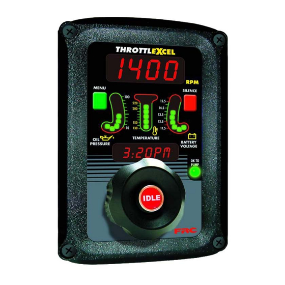
ELA100 Rev0808 Controls and Indicators All controls and indicators are located on the front of the control module. (Refer to Figure 1.) See Operation and Programming Sections for more information. RPM Display Shows the current engine RPM in bright red digits during normal operations. It is used to show error codes, fault warnings, stored data, and program features. -
Page 9: Figure 1. Controls And Indicators
ELA100 Rev0808 Display MENU SILENCE Button Button OIL PRESSURE BATTERY LED Display VOLTAGE LED Display TEMPERATURE LED Display OK TO PUMP Message Display IDLE Remote Hand Button Throttle Control Knob Figure 1. Controls and Indicators... -
Page 10: Installation
Pin 6 on the 12-pin connector at the rear of the control module is provided to connect an optional buzzer. Connect the ground side of the buzzer to pin 6. (Maximum current through pin 6 is 300 mA.) Refer to the Wiring Section. FRC buzzer requires a 1 1/8 inch hole. -
Page 11: Figure 2. Control Module Mounting Dimensions
ELA100 Rev0808 4" 3 1/2" Panel 5 3/4" Cutout Maximum Radius 1/2" Mounting holes are clearance or tapped 5 3/4" for 10-32 screws. 1 3/4" 4 5/8" 6 3/4" Figure 2. Control Module Mounting Dimensions... -
Page 12: Operation
ELA100 Rev0808 OPERATION On power-up the ThrottleXcel is in normal operating mode. The RPM display shows engine RPM, the three LED bar graphs are green indicating readings within normal ranges, and the message display alternates between showing the date and time. If a monitored function is not within normal parameters the display flashes, the RPM display shows an error or fault warning code and a description shows in the message display. -
Page 13: Table 1. Error Codes
ELA100 Rev0808 Table 1. Error Codes Message Display Display Probable Cause NO DATA >Datalink cable not connected / connected to wrong port >Broken wire / bad connector contact on datalink cable NO RPM >Datalink cable not connected / connected to wrong port >Engine not running / ignition key on >Broken wire / bad connector contact on alternator cable Trans... -
Page 14: Display Stored Data
ELA100 Rev0808 Display Stored Data Both the RPM and the message displays are used to show stored data. Accumulated Hours and Transmission Temperature Accumulated hours are stored in memory for engine operation, pump operation, last incident, and current incident. The menu button allows the operator to gain access to this stored data. -
Page 15: High Idle
ELA100 Rev0808 High-Idle The ThrottleXcel programming includes a high-idle function that is controlled by a High-Idle Switch. To activate the high idle, set interlocks as called for by SOP (normally this would include the transmission in neutral and the parking brake on ). Set the High Idle switch to ON. -
Page 16: Programming
ELA100 Rev0808 PROGRAMMING To gain access to the program features a four digit program code must be entered. Review the Program Code Descriptions for the proper four digit code. Both the MENU and SILENCE buttons are used to enter a program code. The RPM display is used to show the codes. -
Page 17: Program Code Descriptions
ELA100 Rev0808 Program Code Descriptions When a valid four digit program code has been entered, stored data or program options will show in the displays. The MENU and SILENCE buttons are used to change the data. The SILENCE button will select the digit that is to be changed. The MENU button will change the digit or change the option choice. -
Page 18: Wiring
- High idle not available for Ford, Mack, or GMC. - The J1939 CAN bus is terminated with a 120 ohm resistor. - When using an FRC provided sensor cable, the red wire is sensor signal and the black wire connects to a ground. -
Page 19: Figure 4. Ela 8-Pin Connector Wiring
ELA100 Rev0808 8-Pin Connector Control Module Pin 1 12-Pin Rear View Connector Pin 1 Vent +12 (24) Ignition Key 8-Pin Cable +12 (24) VDC Pump Engaged 8-Pin Interlock Deutsch Connector Butt Connectors 8 Pin Connector/Cable Wire Color Description Supply Voltage (12/24 VDC) Black Ground Orange... -
Page 20: Cummins Harness Connections
ELA100 Rev0808 Cummins Harness Connections Interface Information The ECM Remote Accelerator (Throttle) Option has to be set to ON. The diagnostic tool cannot be used to do this, an Insight service tool must be used. Refer to an authorized dealer to program this option. 2007 ISB07/ISC07/ISL07 CM 2150D Model Engines +12 (24) - Page 21 ELA100 Rev0808 2007 ISM07 CM 876 Model Engines 2004 to 2006 ISB02/ISC03/ISL03-CM850 Model Engines ISM02-CM870 Model Engines +12 (24) 8-Pin Cable (Refer to Ignition Key Figure 4 ) +12 (24) VDC Pump Engaged Interlock Sensor Supply Remote Accelerator Position ECM Return (Sensor) Remote Accelerator On/Off Switch Max Operating Speed/Governor Type Switch 12-Pin...
-
Page 22: Detroit Diesel (Series 50 And 60) Harness Connections
ELA100 Rev0808 Detroit Diesel (Series 50 and 60) Harness Connections ® 2007 Engine DDEC Interface Information Vehicle Interface Harness 18-PIN Connector #2 ® DDEC J1939 (+) Dk Blu/ J1939 CAN (+) 2/18 Red Wire V-43 12-Pin 2/17 Connector SHIELD (Refer to J1939 (–) Figure 3) Black Wire 2/16... -
Page 23: Navistar Harness Connections
ELA100 Rev0808 Navistar Harness Connections Interface Information The ECM must be programmed for a remote throttle input. When using code 12VZA or 12VXY, the following parameters need to be set: PTO-REMOTE-PEDAL to 1-Yes; PTO-REM-PEDAL-RTZ to 1-RTZ-not; PTO-DISABLE-CAB-INTERFACE to 1-Yes; DRIVELINE-MODE to 1 Datalink 12-Pin Connector... -
Page 24: Caterpillar Harness Connections
ELA100 Rev0808 Caterpillar Harness Connections Interface Information The parameter settings for PTO Cofiguration is programmed to Remote Throttle or Remote Throttle with J1939 Speed Command. ECM software with a Personality Module release date of May08 for C7, C9, C13, C15 engines, will have the Remote Throttle with J1939 Speed Command setting available. - Page 25 ELA100 Rev0808 C10, C12 Engine Interface Engines with 40-Pin OEM connector. Note: Refer to 12-Pin connector Figure 3 for seperate sensor and RPM connections. +12 (24) 8-Pin Cable (Refer to Ignition Key Figure 4 ) +12 (24) VDC Pump Engaged Interlock Multi-Function Input #3 K982-YL...
- Page 26 ELA100 Rev0808 Older Engine Interface Engines with 40-pin OEM connector. 8-Pin Cable (Refer to Figure 4 ) 1 2 1 2 +12 (24) VDC Pump Engaged Interlock Note: Use a plug and receptacle on the Throttle Position Input wire (C986-BR) so the ends can be reconnected if the Throttlexcel is removed.
-
Page 27: Ford Harness Connections
ELA100 Rev0808 Ford Harness Connections 7.3 L Power Stroke Engine Interface The 8-Pin cable needs to be wired to the cab foot throttle harness. Use a voltmeter to determine which pins are 5 V Reference, Idle Validation, and Engine Control Signal. Idle Validation will be at ground. -
Page 28: Figure 10. Ford 6.0L And 6.4L Ela106-B Wiring
+5 Volt Reference Signal Return 6 Pin 6 Pin Deutsch Deutsch Receptacle Plug Note: For wiring on earlier engines contact FRC Engineering. 2005 and Harness Newer Engines To Engine 8 Pin 6.4L Engine 6.0L Engine Connector green/white... - Page 29 ELA100 Rev0808 This page intentionally left blank.
-
Page 30: Mack Harness Connections
ELA100 Rev0808 Mack Harness Connections Interface Information The 8-Pin cable needs to be wired to the cab foot throttle harness. Use a voltmeter to determine which pins are 5 V Reference and Engine Control Signal. Engine Control Signal will be 0.7 volts at idle and rise to approximately 3.8 volts as the foot pedal is pressed. -
Page 31: Scania Harness Connections
ELA100 Rev0808 Scania Harness Connections Interface Information For use on P, R, and T-series trucks equipped with a bodywork control unit (BWS). Connector C259 is available on all vehicles ordered with any of the bodywork options. It is located on the plate for the electrical bodywork interface for body builders. Connector C259 is white and has 21 pins. -
Page 32: Gmc Harness Connections
Notes: Refer to 12-Pin connector Figure 3 ELA 21-Pin Connector Wiring for seperate sensor and RPM connections. When using an FRC provided sensor cable, the red wire is sensor signal and the black wire connects to a ground. -
Page 33: Mercedes Harness Connections
ELA100 Rev0808 Mercedes Harness Connections 2007 Engine 12-Pin ® J1939 (+) DDEC Red Wire 2/18 J1939 CAN (+) Connector Vehicle Interface 2/17 SHIELD (Refer to Harness J1939 (–) Figure 3) Black Wire 2/16 18-PIN J1939 CAN (–) Connector #2 +12 (24) 8-Pin Cable Ignition Key (Refer to... -
Page 34: High Idle Wiring
The high idle is set at about 1000 RPM at the factory. (This value will vary depending on the specific engine.) To adjust this setting refer to High Idle in the Operation Section. Not available for Ford, Mack, or GMC. From A High Idle Kit is available from FRC. Transmission P/N XE-TG38HK-A0A Neutral Includes:... -
Page 35: Flyback Diode Information
(soleniod coil, relay coil, electric motor winding, etc.). It is recommended that a flyback diode be installed on inductive devices that share a common power source/ground with a FRC governor. Typical circuit showing a flyback diode installed across an inductive load.
Need help?
Do you have a question about the ThrottleXcel ELA100 and is the answer not in the manual?
Questions and answers