
Related Manuals for FRC ThrottleXcel ELA100


Summary of Contents for FRC ThrottleXcel ELA100
- Page 1 ELA100 Rev0604 ENGINE THROTTLE AND MONITORING DISPLAY MODEL: ELA100 FIRE RESEARCH CORPORATION www.fireresearch.com 26 Southern Blvd., Nesconset, NY11767 TEL ( 631 ) 724-8888 FAX ( 631 ) 360-9727 TOLL FREE 1-800-645-0074...
-
Page 2: Table Of Contents
ELA100 Rev0604 CONTENTS Table of Contents CONTENTS ....................... 2 INTRODUCTION ...................... 4 Overview ....................... 4 Features ......................... 4 Specifications ......................5 GENERAL DESCRIPTION ..................6 Components ......................6 Controls and Indicators ..................8 INSTALLATION ...................... 10 Install Control Module ..................10 Install Sensors ..................... - Page 3 ELA100 Rev0604 List of Tables Table 1. Error Codes ....................13 Table 2. Fault Warning Codes ................. 13 List of Figures Figure 1. Controls and Indicators ................9 Figure 2. Control Module Mounting Dimensions........... 11 Figure 3. 12-Pin Connector Wiring ................. 18 Figure 4.
-
Page 4: Introduction
When selected by the operator it will show monitored information, stored data, and program options. The ThrottleXcel panel has a built-in FRC infinityPRO remote engine throttle. This hand throttle uses optical technology with an Infrared Encoder (IRE) to detect the direction and speed of the control knob as it is rotated. -
Page 5: Specifications
ELA100 Rev0604 Specifications Display Module Supply Power: 9 - 30 VDC Supply Current: 0.5 Amps Dimensions: 4.5" Wide by 6.75" High LED Bar Graphs Oil Pressure: 10 - 100 PSI (10 PSI Increments) Temperature (Engine Coolant): 130 - 220 °F (10° Increments) Battery Voltage: 11.5 - 16 Volts (0.5 Volt Increments) Sensors... -
Page 6: General Description
ELA100 Rev0604 GENERAL DESCRIPTION The ThrottleXcel all-in-one instrument panel with a remote hand throttle is compatible with the following engines: ELA101 Cummins IS Series ELA102 Detroit Diesel ELA104 Navistar ELA105 Caterpillar ELA106* Ford ELA107 Mack ELA108 Scania ELA109* GMAC ELA110 Mercedes * Note: An adapter and cable assembly replaces the basic 8-pin cable when connecting the ThrottleXcel to a Ford 6.0 or GMAC engine. - Page 7 ELA100 Rev0604 Engine Coolant Temperature Sensor The engine coolant temperature sensor is installed as necessary. Oil Pressure Sensor The oil pressure sensor is installed as necessary. Transmission Temperature Sensor (Optional) The optional transmission fluid temperature sensor is installed as necessary. Cables There are two cables that connect to the control module.
-
Page 8: Controls And Indicators
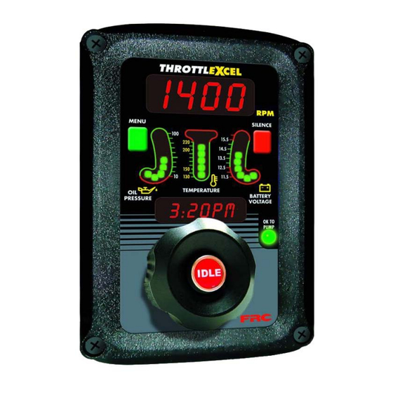
ELA100 Rev0604 Controls and Indicators All controls and indicators are located on the front of the control module. (Refer to Figure 1.) See Operation and Programming Sections for more information. RPM Display Shows the current engine RPM in bright red digits during normal operations. It is used to show error codes, fault warnings, stored data, and program features. -
Page 9: Figure 1. Controls And Indicators
ELA100 Rev0604 Display MENU SILENCE Button Button OIL PRESSURE BATTERY LED Display VOLTAGE LED Display TEMPERATURE LED Display OK TO PUMP Message Display IDLE Remote Hand Button Throttle Control Knob Figure 1. Controls and Indicators... -
Page 10: Installation
ELA100 Rev0604 INSTALLATION Install Control Module 1. Measure and mark mounting location for control module panel cutout and mounting screw holes. Make sure there is clearance behind the panel for the module and cables before cutting holes. Refer to Figure 2 for layout and dimensions. -
Page 11: Figure 2. Control Module Mounting Dimensions
ELA100 Rev0604 4" 3 7/16" Panel 5 3/4" Cutout Maximum Radius 1/2" Mounting holes are clearance or tapped 5 11/16" for 10-32 screws. 1 3/4" 4 5/8" 6 3/4" Figure 2. Control Module Mounting Dimensions... -
Page 12: Operation
ELA100 Rev0604 OPERATION On power-up the ThrottleXcel will be in normal operating mode. The RPM display will show engine RPM, the three LED bar graphs will be green indicating readings within normal ranges, and the message display will alternate between showing the date and time. -
Page 13: Table 1. Error Codes
ELA100 Rev0604 Table 1. Error Codes Message Display Display Probable Cause NO DATA >Datalink cable not connected / connected to wrong port >Broken wire / bad connector contact on datalink cable NO RPM >Datalink cable not connected / connected to wrong port >Engine not running / ignition key on >Broken wire / bad connector contact on alternator cable TRANS T’... -
Page 14: Display Stored Data
ELA100 Rev0604 Display Stored Data Both the RPM and the message displays are used to show stored data. Accumulated Hours Accumulated hours are stored in memory for engine operation, pump operation, last incident, and current incident. The menu button allows the operator to gain access to this stored data. -
Page 15: High Idle
ELA100 Rev0604 High Idle The ThrottleXcel programming includes a high idle function. To activate the high idle provide 12 VDC to pin 7 (High Idle Active Input) and pin 8 (High Idle Throttle Enable Input) of the 12-pin connector. It is recommend to connect pin 7 to the high idle switch (not provided) and pin 8 to the safety interlock circuit. -
Page 16: Programming
ELA100 Rev0604 PROGRAMMING To gain access to the program features a four digit program code must be entered. Review the Program Code Descriptions for the proper four digit code. Both the MENU and SILENCE buttons are used to enter a program code. The RPM display is used to show the codes. -
Page 17: Program Code Descriptions
ELA100 Rev0604 Program Code Descriptions When a valid four digit program code has been entered, stored data or program options will show in the displays. (Refer to Programming.) The MENU and SILENCE buttons are used to change the data. The SILENCE button will select the digit that is to be changed. -
Page 18: Wiring
ELA100 Rev0604 WIRING The following figures include the schematics, wiring diagrams, block diagrams, and cables for the ThrottleXcel. Connectors and Cables 12-Pin 1 2 1 2 Deutsch Connector 12-Pin Cable Butt Connectors 12 Pin Connector/Cable Wire Color Description Engine Oil Press. Sensor Signal Engine Temp. -
Page 19: Figure 4. 8-Pin Connector Wiring
ELA100 Rev0604 8-Pin Connector Control Pin 1 12-Pin Module Rear Connector View Pin 1 Note: An adapter and cable assembly replaces the basic 8-pin cable when connecting the ThrottleXcel to a Ford 6.0 or GMAC engine. Refer to the engine specific wiring diagram. 8-Pin Deutsch Connector... -
Page 20: Cummins Harness Connections
ELA100 Rev0604 Cummins Harness Connections Interface Information The ECM Remote Accelerator (Throttle) Option has to be set to ON. The diagnostic tool cannot be used to do this, an Insight service tool must be used. Refer to an authorized dealer to program this option. ISB, ISC, and ISL Engine Interface +12 (24) 8-Pin Cable... - Page 21 ELA100 Rev0604 ISM Engine Interface +12 (24) 8-Pin Cable (Refer to Ignition Key Figure 3 ) 1 2 1 2 +12 (24) VDC Pump Engaged Interlock ACCELERATOR SUPPLY (+) REMOTE ACCELERATOR POSITION ACCELERATOR SUPPLY RETURN REMOTE ACCELERATOR SWITCH ACCELERATOR GOVERNOR SWITCH ECM 50-Pin C1 Connector Sensor Supply...
-
Page 22: Detroit Diesel (Series 50 And 60) Harness Connections
ELA100 Rev0604 Detroit Diesel (Series 50 and 60) Harness Connections Interface Information There may be a 3-pin Packard connector (Variable Speed Governor Harness Connector installed by the chassis manufacturer) located behind the pump panel to plug into for the ECM connections. +12 (24) 8-Pin Cable (Refer to... -
Page 23: Navistar And Detroit Diesel (Series 40) Harness Connections
ELA100 Rev0604 Navistar and Detroit Diesel (Series 40) Harness Connections Interface Information The ECM must be programmed for a remote throttle input. Set PTO REMOTE PEDAL to 1. (This will enable the remote throttle input.) +12 (24) 8-Pin Cable (Refer to Ignition Key Figure 3 ) 1 2 1 2... -
Page 24: Caterpillar Harness Connections
ELA100 Rev0604 Caterpillar Harness Connections Interface Information The ECM Remote Throttle Option has to be enabled. Refer to an authorized dealer to program this option. 3116B, 3126B, 3176B, 3406E, C7, C10, C12 Engine Interface Engines with 70-pin OEM connector. +12 (24) 8-Pin Cable (Refer to Ignition Key... - Page 25 ELA100 Rev0604 3176B, 3406E, C10, C12 Engine Interface Engines with 40-pin OEM connector. +12 (24) 8-Pin Cable (Refer to Ignition Key Figure 3 ) +12 (24) VDC Pump Engaged Interlock Multi-Function Input #3 K982-YL Remote Throttle PWM Multi-Function Input #1 K999-GN PTO ON/OFF Switch 40-Pin...
- Page 26 ELA100 Rev0604 Older Engine Interface Engines with 40-pin OEM connector. 8-Pin Cable (Refer to Figure 3 ) 1 2 1 2 +12 (24) VDC Pump Engaged Interlock Note: Use a plug and receptacle on the Throttle Position Input wire (C986-BR) so the ends can be reconnected if the Throttlexcel is removed.
-
Page 27: Ford Harness Connections
ELA100 Rev0604 Ford Harness Connections 7.3 L Power Stroke Engine Interface The 8-Pin cable needs to be wired to the cab foot throttle harness. Use a voltmeter to determine which pins are 5 V Reference, Idle Validation, and Engine Control Signal. Idle Validation will be at ground. -
Page 28: Figure 10. Ford 6.0L Ela106-B Wiring
ELA100 Rev0604 6.0 L Diesel Engine Interface An adapter and cable assembly part number ET4106B is needed to interface the ELA106B with the 6.0 L engine. Two 6 pin connectors are provided and need to be spliced into the harness between the cab foot throttle and the ECM. +12 (24) Ignition Key +12 (24) VDC... - Page 29 ELA100 Rev0604 Ford Adapter and Cable Detail (6.0 L Engines) Adapter Connector/Cable Wire Color Description Supply Voltage (12 or 24 VDC) Black Ground Blue +5 VDC Reference From ECM White Throttle Signal To ECM Brown Signal Return From ECM Yellow Interlock Input (12 or 24 VDC) Green Third Gear Lock-up...
- Page 30 From Pin 7 (See Sheet 2) Green wire will go low when the engine RPM goes above the program third gear lock-up setting. Green Wire Wire +12 VDC FRC Torque Lock-up Module Black Wire White Blue Wire Wire To Transmission...
- Page 31 ELA100 Rev0604 This page intentionally left blank.
-
Page 32: Mack Harness Connections
ELA100 Rev0604 Mack Harness Connections Interface Information The 8-Pin cable needs to be wired to the cab foot throttle harness. Use a voltmeter to determine which pins are 5 V Reference and Engine Control Signal. Engine Control Signal will be 0.7 volts at idle and rise to approximately 3.8 volts as the foot pedal is pressed. -
Page 33: Scania Harness Connections
ELA100 Rev0604 Scania Harness Connections Interface Information The 8-Pin cable needs to be wired to the cab foot throttle harness. Use a voltmeter to determine which pins are 5 V Reference, Idle Validation, and Engine Control Signal. Idle Validation Switch (white wire) will be at 24 VDC. When the foot pedal is pressed it will dorp to ground. -
Page 34: Gmac Harness Connections
ELA100 Rev0604 GMAC Harness Connections Interface Information An adapter and cable assembly is needed to interface the ELA109 with GMAC engines. There are two available: ET-902-HA for 2002 and Earlier Model Engines ET-902-HB for 2003 Engines +12 (24) Ignition Key +12 (24) VDC Pump Engaged Interlock... - Page 35 ELA100 Rev0604 GMAC Adapter and Cable Detail Adapter Connector/Cable Wire Color Description Supply Voltage (12 or 24 VDC) Black Ground Blue +5 VDC Reference From ECM White Throttle Signal To ECM Brown Signal Return From ECM Yellow Interlock Input (12 or 24 VDC) Green Throttle Enable Signal Black...
-
Page 36: Mercedes Harness Connections
ELA100 Rev0604 Mercedes Harness Connections +12 (24) 8-Pin Cable (Refer to Ignition Key Figure 3 ) 1 2 1 2 +12 (24) VDC Pump Engaged Interlock Remote Throttle Signal Analog Remote PTO Power Supply Throttle Select 18-Pin Connector Sensor Ground (Throttle Pedal &... -
Page 37: Figure 15. Mercedes Euro Ela110B Wiring
ELA100 Rev0604 ELA110B Euro Version Interface Information It is required that parameter 500 output from the manual throttle actuator speed has YES stored as a parameter. +12 (24) 8-Pin Cable (Refer to Ignition Key Figure 3 ) 1 2 1 2 +12 (24) VDC Pump Engaged Interlock...
Need help?
Do you have a question about the ThrottleXcel ELA100 and is the answer not in the manual?
Questions and answers