
Related Manuals for FRC InView 360 HD AVM


Summary of Contents for FRC InView 360 HD AVM
- Page 1 Document Number: XE-SNB100-C00-INSTALLPM-R0A Around Vehicle Monitoring System Installation Guide © Safe Fleet | July 2020 | All rights reserved © Safe Fleet | All rights reserved...
-
Page 2: Table Of Contents
360 HD Installation Guide AVM Around Vehicle Monitoring System Installation Guide Contents Introduction ����������������������������������������������������������������������������������������������������������������������������������������� 3 How Does the inView 360 HD AVM Work? ������������������������������������������������������������������������������������������������������������������ 3 Installation Process ����������������������������������������������������������������������������������������������������������������������������� 4 Preparing for Installation ��������������������������������������������������������������������������������������������������������������������� 4 Kit Components ������������������������������������������������������������������������������������������������������������������������������������������������������������ 4 Mounting the ECU ������������������������������������������������������������������������������������������������������������������������������ 7 Accessibility ������������������������������������������������������������������������������������������������������������������������������������������������������������������... -
Page 3: Introduction
Large vehicles, due to their size and shape, often have areas which drivers cannot see unaided. By providing drivers with a full 360° view of the area around their vehicles, the inView 360 HD AVM helps to eliminate these vehicle “blind spots”, contributing to the reduction of collisions with surround pedestrians and vehicles. -
Page 4: Installation Process
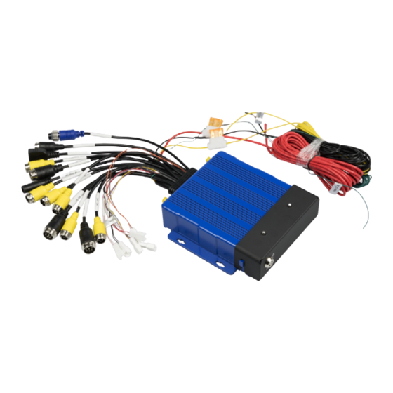
inView 360 HD Installation Guide AVM Around Vehicle Monitoring System Installation Guide Installation Process There are multiple steps to be performed by different team members: 1� Prepare for Installation 2� Install the inView 360 HD system 3� Calibrate the inView 360 HD system (See the inView 360 HD System Calibration Guide) 4�... - Page 5 inView 360 HD Installation Guide AVM Around Vehicle Monitoring System Installation Guide 1 x Cable Harness Power Lines 1 x ECU w/Lock-Removable Front Cover 4 x Camera Cable Extensions In 3 different lengths: • 8m front • 12m left, right •...
- Page 6 inView 360 HD Installation Guide AVM Around Vehicle Monitoring System Installation Guide 1 x Ethernet Adapter 4 x Camera Modules 2.9 MP 4 x Camera Housings (Not used during calibration�) 1 x Y-Splitter 1 x Event Button Cable Harness 1 x Outrigger Button Cable Harness 1 x External GPS Antenna 1 x External Wi-Fi Antenna 1 x Dashboard Push Button...
-
Page 7: Mounting The Ecu
inView 360 HD Installation Guide AVM Around Vehicle Monitoring System Installation Guide Mounting the ECU The ECU should be mounted in a location underneath the dashboard or somewhere within the vehicle where it is protected from water, dirt, and physical contact, and it should have ample ventilation� Accessibility Position the ECU so that the front side of the unit is accessible�... -
Page 8: Placing Cameras
inView 360 HD Installation Guide AVM Around Vehicle Monitoring System Installation Guide Placing Cameras It is important to keep vehicle type/shape in mind when considering camera placement� Also, it is important to keep in mind the physicality of the vehicle when placing cameras� Watch out for mirrors and other vehicle elements that can create a blind spot in the camera view�... -
Page 9: Camera Placement Considerations For Specially Shaped Vehicles
inView 360 HD Installation Guide AVM Around Vehicle Monitoring System Installation Guide Camera Placement Considerations for Specially Shaped Vehicles Vehicles that have special compartments or equipment in the middle, such as fire trucks, might require special consideration for mounting cameras� Because of the accessories and equipment that is usually added to emergency vehicles, mounting the cameras high up and in the center might not be an option�... -
Page 10: Putting The Components Together
inView 360 HD Installation Guide AVM Around Vehicle Monitoring System Installation Guide Putting the Components Together Connecting to the Power Source When connecting to the power sources, please ensure the following: • Red goes to vehicle power • Yellow goes to vehicle ignition •... -
Page 11: Connecting Cameras To The Ecu
NOTE: Extra Camera Ports NOTE: Spacing the Calibration Pads The inView 360 HD AVM system comes with two extra camera ports for cameras 5 and 6� Cameras connected to ports 5 and 6 are not required for the calibration procedure�... -
Page 12: Connecting Monitors And Recorders
Fleet for assistance� If you are installing the inView 360 HD AVM as a standalone system (without a Safe Fleet DVR or NVR), then you can simply connect the monitor directly to the ECU harness’ CVBS cable or to the VGA cable. -
Page 13: Connecting The Ecu To A Monitor And A Second Device Via The Cvbs Connector
inView 360 HD Installation Guide AVM Around Vehicle Monitoring System Installation Guide Connecting the ECU to a Monitor and a Second Device via the CVBS Connector A Y-Splitter can be used to split the CVSB video line to connect either a Safe Fleet recorder or a second standard resolution monitor�... -
Page 14: Connecting The Ecu To A Hd Monitor (Via Vga) And A Recorder (Via Cvbs)
inView 360 HD Installation Guide AVM Around Vehicle Monitoring System Installation Guide Connecting the ECU to a HD Monitor (via VGA) and a Recorder (via CVBS) If your monitor is an HD monitor, then you can connect it to the ECU via the VGA connector� In this scenario, the system can be configured to turn off video to the HD monitor (for safety), and because the recorder is on the separate CVBS video feed, the recording is not interrupted�... -
Page 15: Connecting The Ecu To Up To Three Devices
inView 360 HD Installation Guide AVM Around Vehicle Monitoring System Installation Guide Connecting the ECU to Up to Three Devices Using a combination of the VGA and CVBS video lines, you can connect up to three devices of the following combinations: •... -
Page 16: Connecting The Push Buttons
Connecting the Push Buttons The inView 360 HD AVM system kit comes with three push buttons that, with the use of the dashboard push button mount/ template, can be mounted in the vehicle within the driver’s reach. Although the buttons can be configured to suit each customer’s needs, we suggest that they are configured to do the following:... - Page 17 inView 360 HD Installation Guide AVM Around Vehicle Monitoring System Installation Guide Dashboard Push Button Mount/Template 2� Use the correct harness to connect each switch to the ECU� Black Push Outrigger Button Cable Harness Button Switch Driver/Event Button Cable Harness Green Push Button Switch Event Button Cable Harness...
-
Page 18: Connecting Antennas And An Ir Receiver
After you have successfully installed each of the system’s components, you’ll need to use the software to calibrate the cameras� Please see the inView 360 HD AVM Calibration Guide for more about the calibration procedures� © Safe Fleet | July 2020 | All rights reserved p. -
Page 19: Contacting Frc (Fire Research Corporation)
This page can be found through the above link for the FRC website� Go to the Manuals tab (under the Resources menu item), and then scroll all the way down to the bottom of this page� There is a link for the Warranty Policy PDF under the Reference/Data Sheets header�...
Need help?
Do you have a question about the InView 360 HD AVM and is the answer not in the manual?
Questions and answers