Table of Contents

Subscribe to Our Youtube Channel
Related Manuals for FRC Air Sentinel AMA200


Summary of Contents for FRC Air Sentinel AMA200
- Page 1 AMA200 Rev150720 Document Number: XE-AMA2PM-R0A BREATHING AIR MONITORING SYSTEM MODEL AMA200 FIRE RESEARCH CORPORATION www.fireresearch.com 26 Southern Blvd., Nesconset, NY 11767 TEL 631.724.8888 FAX 631.360.9727 TOLL FREE 1.800.645.0074...
-
Page 2: Table Of Contents
AMA200 Rev150720 CONTENTS Table of Contents CONTENTS ........................ 2 INTRODUCTION ...................... 3 Overview ........................ 3 Features ........................3 Specifications ......................3 GENERAL DESCRIPTION ..................4 Components ......................4 Controls and Indicators ..................5 INSTALLATION ......................6 Install Display Module................... 6 Install Pressure Sensor ................... -
Page 3: Introduction
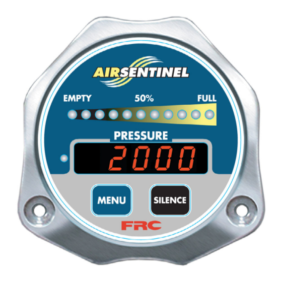
AMA200 Rev150720 INTRODUCTION Overview The Breathing Air Monitoring System is designed for use on aerial devices. It has 11 LEDs that indicate the percentage of air in the bottle. When the air in the bottle drops below the low air setting, the LEDs flash. A 5-digit LED display shows the actual bottle pressure. -
Page 4: General Description
AMA200 Rev150720 GENERAL DESCRIPTION Components The Breathing Air system consists of the following components: Display Module Pressure Sensor Audible Alarm Buzzer Cables Display Module The display module is waterproof and has dimensions less than 3 1/4 inches high by 3 1/4 inches wide by 2 inches deep. All controls and indicators are located on the front of the display module. -
Page 5: Controls And Indicators
AMA200 Rev150720 Controls and Indicators All controls and indicators are located on the front of the display module. The intensity of the display and LEDs are automatically adjusted for day or night operation. LED Bar Graph The LED bar graph display indicates the remaining percentage of air in the bottle, this will be proportional to the pressure sensor input. -
Page 6: Installation
AMA200 Rev150720 INSTALLATION Install Display Module Display modules are interchangeable. Programming may have to be set for primary/ remote operations. 1. Measure and mark mounting location for display module panel cutout and mounting screw holes. Make sure there is clearance behind the panel for the display and cables before cutting holes. -
Page 7: Install Pressure Sensor
AMA200 Rev150720 Install Pressure Sensor The pressure sensor is mounted on the manifold of the air tank. T-fittings can be used to mount the pressure sensor. 1. Screw the sensor into a 1/4-18 NPT hole. Caution: Do not use the main body that houses the electronics to tighten the pressure sensor. -
Page 8: Install Buzzer
Install the buzzer close to the display module so the audible warning is easily associated with the visual warning on the display. The optional buzzer provided by FRC requires a cutout hole of 1-1/8" (1.125"). Pin 6 on the 8-pin connector at the rear of the control module is provided to connect the optional buzzer. -
Page 9: Operation
AMA200 Rev150720 OPERATION On power-up the Breathing Air system is in the normal operating mode. Information from the pressure sensor or from the datalink interface is processed and displayed. Operator input is necessary only when accessing program information. The digital display indicates bottle pressure above 500 PSI in increments of 10. (If the display module is programmed for the units of measure to be Bar, it shows one digit to the right of the decimal point.) The bar graph display shows the percentage of air in the bottle in ten percent... -
Page 10: Test Mode
AMA200 Rev150720 Test Mode The test mode is used to test all LEDs, alarm outputs, and communication links between primary and remote display modules. The test mode will not activate when there is a low pressure warning. 1. Press and hold the SILENCE button. Result: The audible alarm sounds. -
Page 11: Programming
AMA200 Rev150720 PROGRAMMING The program access mode is selected and inputs are made using the two pushbutton switches on the front of the display module. The digital display shows stored data and operator inputs. (Refer to Figure 1.) Note: When entering codes in the program access mode there is a time-out feature that requires an operator input every three seconds. -
Page 12: Program Access Mode
AMA200 Rev150720 Program Access Mode To gain access to the program features a three-digit program code must be entered. Review the Program Code Descriptions or refer to Table 1. Program Code Quick Reference for the proper three-digit code. Note: There is a time-out feature that returns the program to normal operation in five seconds if input is not detected. - Page 13 AMA200 Rev150720 Table 1. Program Code Quick Reference CODE FEATURE OPTION ID Number 0 to 99 Module Function Pri, SLA Unit of Measure/ PSI, kPa, BAR Full Bottle Pressure 0 to 8000 Low Air Warning 20 to 99 (%) Audible Alarm 00 to 99 CAN Terminator On, Off...
-
Page 14: Program Code Descriptions
AMA200 Rev150720 Program Code Descriptions When a valid three-digit program code has been entered, a program value or option shows in the display. The MENU and SILENCE buttons are used change the data. Press the MENU button to select the digit to be change. The digit flashes. Press the SILENCE button to change the digit or the option choice. - Page 15 AMA200 Rev150720 Options: 00 - 99 This code sets the time interval (1 to 99 minutes) after the silence button is pressed until the audible alarm sounds again. If set to 0, the alarm will not repeat after the silence button is pressed. Code 340 CAN Terminator Factory programmed value: Options:...
-
Page 16: Wiring
AMA200 Rev150720 WIRING The following figures include wiring and cable information. Display Module A remote display module requires four (4) wires, power (pins 1 and 2) and the datalink connection (pins 7 and 8) to the primary display. A remote display must be programmed with the same ID number as the primary display. -
Page 17: Pressure Sensor
AMA200 Rev150720 Pressure Sensor Pressure Sensor (Top View) Supply Voltage Signal Output Sensor Cable from Ground 8-Pin Connector Pressure Sensor (Side View) Vent Port Figure 5. Pressure Sensor Wiring... -
Page 18: Ama210
AMA200 Rev150720 AMA210 The AMA210 kit includes a 8-pin connector with butt crimps. When the pressure sensor kit is ordered separate it has a connector with three wires that needs to be connected to the display module. 8-Pin Connector Wiring Wire Color Description Power Black... - Page 19 AMA200 Rev150720 NOTES...
- Page 20 AMA200 Rev150720...
Need help?
Do you have a question about the Air Sentinel AMA200 and is the answer not in the manual?
Questions and answers