Table of Contents

Related Manuals for FRC Insight Ultimate Series


Summary of Contents for FRC Insight Ultimate Series
- Page 1 FP4000 Rev0204 PRESSURE GAUGE AND DIGITAL FLOWMETER MODEL: FP4000 Insight Ultimate Series FIRE RESEARCH CORPORATION fireresearch.com 26 Southern Blvd., Nesconset, NY11767 TEL ( 631 ) 724-8888 FAX ( 631 ) 360-9727 TOLL FREE 1-800-645-0074...
-
Page 2: Table Of Contents
FP4000 Rev0204 CONTENTS Table of Contents CONTENTS ....................... 2 List of Tables ......................3 List of Figures......................3 INTRODUCTION ...................... 4 Overview ....................... 4 Features........................4 Specifications ......................5 GENERAL DESCRIPTION ..................6 Components ......................6 Controls and Indicators ..................7 INSTALLATION ....................... -
Page 3: List Of Tables
FP4000 Rev0204 List of Tables Table 1. Pressure Transducer Output Voltage ............5 Table 2. Program Code Quick Reference ..............25 List of Figures Figure 1. Controls and Indicators ................7 Figure 2. Display Module Mounting Dimensions ............. 9 Figure 3. Flow Sensor Location Guidelines ............11 Figure 4. -
Page 4: Introduction
LED flow display into one practical display module. The pressure gauge/flowmeter is able to communicate with other display modules over the FRC datalink. This technology allows for remote displays, the display of flow for multiple discharges (summing), and the totalization of flow for multiple discharges (accumulation). -
Page 5: Specifications
FP4000 Rev0204 Specifications Display Module Supply Voltage: 9 - 30 VDC Supply Current: 1.0 Amp Dimensions: Height 4.4 Inches Width 4.4 Inches Depth 3.4 Inches Datalink Protocol: J1939 CAN Flow Sensor Type: Paddlewheel with Brass Housing for Saddle Clamp or Weldment Mount (Stainless Steel Housing Optional) Sensor Material: Acetal (Delrin) with Stainless Steel (316) Shaft... -
Page 6: General Description
FP4000 Rev0204 GENERAL DESCRIPTION Components The INSIGHT ULTIMATE pressure gauge/flowmeter consists of the following components: Display Module Pressure Transducer Paddlewheel Flow Sensor and Sensor Housing Assembly External Module Totalizing Button (Optional) Cables Display Module The pressure gauge/flowmeter display module is waterproof and has dimensions of 4.4 inches high by 4.4 inches wide by 3.4 inches deep. -
Page 7: Controls And Indicators
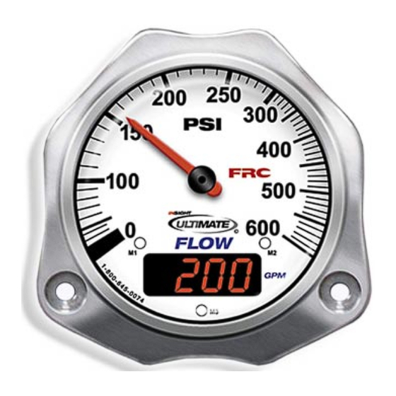
FP4000 Rev0204 Controls and Indicators All controls and indicators are located on the front of the display module. It contains the pressure scale and indicating needle, a digital display, and the three magnet sensors. (Refer to Figure 1.) Pressure Display The pressure scale is non-linear and is expanded between 100 and 250 PSI. -
Page 8: Installation
FP4000 Rev0204 INSTALLATION The FP4000 display module, flow sensor, and pressure transducer are compatible for use with any size piping. Note: Plumbing systems are always unique and may cause small deviations in the factory calibration. It is recommended that the calibration procedure be performed after installation. -
Page 9: Figure 2. Display Module Mounting Dimensions
FP4000 Rev0204 Panel Cutout 3.75" Diameter Hole Tap or Drill Clearence Hole for 10-32 Screw 1.25" 3.63" 2.80" 10-32 Mounting Screw 3.74" 4.34" .60" 4.36" Figure 2. Display Module Mounting Dimensions... -
Page 10: Install Flow Sensor
FP4000 Rev0204 Install Flow Sensor There are several ways to install FRC paddlewheel type flow sensors. Mounting options include saddle clamps, weldments, pipe tees, and special adapters. Each mount will meet particular plumbing requirements. Flow sensors are interchangeable. It is recommended that the calibration be checked if flow sensors are swapped. -
Page 11: Figure 3. Flow Sensor Location Guidelines
FP4000 Rev0204 The preferred location for the mounting of a flow sensor is on the top half of the pipe. The best orientation is vertical. If the sensor is mounted on the bottom of the pipe, it may be susceptible to the accumulation of dirt. - Page 12 FP4000 Rev0204 Saddle Clamp Installation Note: Ensure that the mounting location meets the requirements for uniform water flow. (Refer to Flow Sensor Location.) Note: Ensure that there is enough room for the saddle clamp, sensor, and connector to fit. (Refer to Figure 4.) 1.
-
Page 13: Figure 4. Saddle Clamp Installation
FP4000 Rev0204 Retainer Cap Pipe Size Dimensions (Sch 40) O-Ring Paddlewheel Flow Sensor Alignment Measurements are in inches. Sensor Housing Saddle Clamp Note: Allow a minimum of 2 inches clearance at the sensor top for removal/installation of the connector. Note: When the retainer cap is tightened make sure the sensor rim flat spot does not disengage from the alignment tab and... - Page 14 FP4000 Rev0204 Weldment Installation Note: Ensure that the mounting location meets the requirements for uniform water flow. (Refer to Flow Sensor Location.) Note: Ensure that there is enough room for the weldment, sensor, and connector to fit. (Refer to Figure 5.) 1.
-
Page 15: Figure 5. Weldment Installation
FP4000 Rev0204 Retainer Cap Pipe Size Dimension O-Ring (Sch 40) 1.95 to 1.80 Paddlewheel 1.95 to 1.80 Flow Sensor 1.90 to 1.75 1.88 to 1.73 Tru-Seal 1.88 to 1.73 Locknut 1.85 to 1.70 Measurements are in inches. Alignment Sensor Make sure that the alignment tab is Housing centered on the pipe centerline. -
Page 16: Install Pressure Transducer
FP4000 Rev0204 Install Pressure Transducer The pressure transducer is mounted on the downstream side of the discharge valve. Pressure transducers are interchangeable. It is recommended that the calibration be checked if pressure transducers are swapped. Note: Install the pressure transducer upright so water in the end of the pressure transducer is able to drain back into the pipe. -
Page 17: Install External Totalizing Button Option
FP4000 Rev0204 Install External Totalizing Button Option 1. Mount a momentary on (SPST) switch near the display. 2. Connect a wire from one terminal of the switch to ground. 3. Connect a wire from the other terminal of the switch to pin 10 on the display module connector. -
Page 18: Operation
(with the optional external button) or accessing program information. Datalink Interface The FRC datalink interface is standard on all pressure gauge/flowmeters and provides a way of connecting multiple display modules on a shared data bus. The FP4000 (pressure gauge/flowmeter) and DF4000 (digital flowmeter) series display... -
Page 19: Figure 7. Typical Datalink
FP4000 Rev0204 REMOTE PANEL(S) FLOWMETER FLOWMETER INSIGHT INSIGHT Function: Function: Function: Function: ID Number: ID Number: ID Number: ID Number: Id 2 Id 4 Id 1 Id 3 Datalink Accumulator display PUMP red LED will be on to PANEL indicate x 100 scale. Note: A single display module can be used for Function: FLOWMETER... -
Page 20: Program Features
FP4000 Rev0204 Program Features See Programming section for more detailed information. High and Low Flow Warning (Codes 315 and 316) When the flow rate is above the programmed high flow value a flashing -HI- will show in the digital display. When the flow rate is below the programmed low flow value a flashing -LO- will show in the digital display. -
Page 21: Programming
FP4000 Rev0204 PROGRAMMING The two operator selectable modes are display module identification and program access. These modes are selected and inputs are made by using the three magnet sensors on the front of the display module. The digital display will show stored data and operator inputs. -
Page 22: Figure 8. Typical Programming Displays
FP4000 Rev0204 DISPLAY MODULE IDENTIFICATION MODE Serial Number: This is set at the factory. Manufactured Date: This is set at the factory (mm.yy). Software Revision: This is set at the factory. Module Function: To change use program access code 313. ID Number: To change use program access code 312. -
Page 23: Program Access Mode
FP4000 Rev0204 Program Access Mode When in the program access mode the digital display will show operator inputs, program options, and error codes. To gain access to the program features a three digit program code must be entered. Review the Program Code Descriptions or refer to Table 2. -
Page 24: Program Code Descriptions
FP4000 Rev0204 Program Code Descriptions When a valid three digit program code has been entered a program value or option will show in the display. The M1 and M2 sensors are used change the data. The M1 sensor will select the digit that is to be changed. The digit will flash. The M2 sensor will change the digit that is flashing or change the option choice. -
Page 25: Table 2. Program Code Quick Reference
Select Different Calibration Point E208 Memory Failure Contact FRC • Refer to Program Code Descriptions for detailed information. • There is a timeout feature that will return the program to normal operation in three seconds if input is not detected at the magnet sensors. - Page 26 FP4000 Rev0204 Code 316 Low Flow Warning Factory programmed value:0 (Low flow warning is disabled.) Options: 0001 to 9999 This code will allow the low flow rate warning to be set. When the flow rate is below the low flow warning program value, the flow display will alternately flash between the flow rate and -LO- .
- Page 27 Select a different point to continue with the calibration procedure. Error Code E208 There is a failure with the internal memory of the module. Contact FRC if this error code is displayed. Exit Program Access Mode Touch the magnet on the glass at the M3 sensor and hold it there until four dashes are shown in the display.
-
Page 28: Calibration
FP4000 Rev0204 CALIBRATION The INSIGHT ULTIMATE pressure gauge and digital flowmeter is precalibrated and tested at the factory. Plumbing systems are always unique and may cause small deviations in the factory calibration. The pressure gauge/flowmeter should be checked after installation for accuracy and calibrated when necessary. To calibrate the digital flowmeter use a precalibrated water flow test kit (connected to the discharge according to the instructions provided with the test kit) or a pitot gauge as a reference. - Page 29 FP4000 Rev0204 Flow Calibration, Multiple Point (Code 322) This function allows for the display to be calibrated at multiple flow rates. It corrects for nonlinear flow in difficult to plumb locations to provide an accurate flow rate display. Select flow rates to calibrate (up to 10 calibration points) that are within the most commonly used flow range for the discharge.
- Page 30 FP4000 Rev0204 Pressure Calibration (Code 323) To calibrate the pressure gauge use a calibrated test gauge or a master pressure gauge as a reference. During the calibration procedure the pressure indicating needle will not move. This procedure sets the pressure values in the program. During normal operation the microprocessor controls the needle movement.
- Page 31 FP4000 Rev0204 This page intentionally left blank.
-
Page 32: Wiring
FP4000 Rev0204 WIRING FP4000 Connector Signal Description Power 9 - 30 VDC Ground Flow Sensor 5 VDC Flow Sensor Ground Flow Sensor Signal Pressure Sensor 5 VDC Pressure Sensor Ground Pressure Sensor Signal External Totalizer Button Datalink CAN Low Datalink CAN High Note: Connect the black ground wire (pin 2) to battery negative (–) or a good chassis ground (the chassis... -
Page 33: Figure 10. Remote Display Wiring
FP4000 Rev0204 Remote Display Note: The remote display connector pinouts are the same as the primary display connector pinouts. Note: Minimum wire size for power is 18 AWG. To Primary Display Connector Black Wire to Pin 11 Red Wire to Pin 12 Black Wire Ground Red Wire... -
Page 34: Parts List
FP4000 Rev0204 PARTS LIST Index FRC Part No. Description FP-4000-X.X Insight Ultimate Kit (GPM/PSI) FP-4010-X.X Insight Ultimate Kit (LPM/kPA) FP-4020-X.X Insight Ultimate Kit (LPM/Bar) X.X = Pipe Size FP-4000-DM . Ultimate Display (GPM/PSI) FPC-4K-XX . Primary Display Cable XX = Cable Length (In Feet) FP3100PT2 . - Page 35 FP4000 Rev0204 This page intentionally left blank.
Need help?
Do you have a question about the Insight Ultimate Series and is the answer not in the manual?
Questions and answers