
Related Manuals for Oshkosh Corporation JLG 1250AJP


Summary of Contents for Oshkosh Corporation JLG 1250AJP
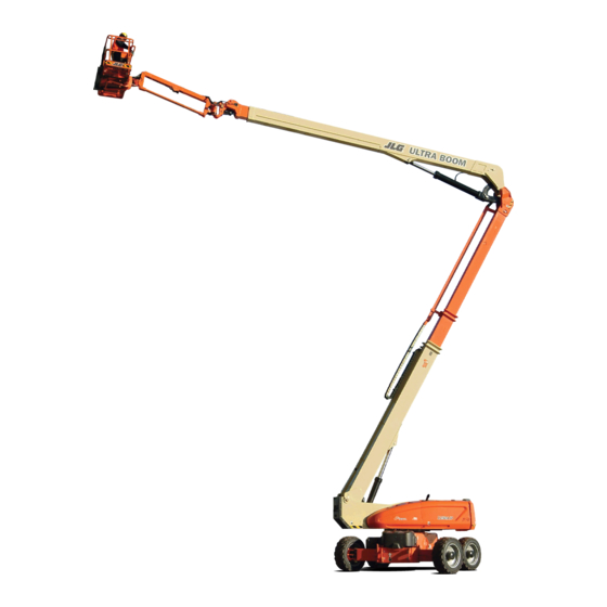
- Page 1 Operation and Safety Manual Original Instructions - Keep this manual with the machine at all times. Model 1250AJP PVC 2001 AS/NZS ANSI 31215057 August 26, 2020 - Rev C ®...
- Page 2 WARNING Operating, servicing and maintaining this vehicle or equipment can expose you to chemicals including engine exhaust, carbon monoxide, phthalates, and lead, which are known to the State of California to cause cancer and birth defects or other reproductive harm. To minimize exposure, avoid breathing exhaust, do not idle the engine except as necessary, service your vehicle or equipment in a well-ventilated area and wear gloves or wash your hands frequently when servicing.
- Page 3 FOREWORD FOREWORD The Mobile Elevating Work Platform (MEWP) models covered in this manual are designed and tested to meet or exceed var- ious compliance standards. Please refer to the manufacturer’s nameplate affixed to the subject MEWP for specific standard compliance information. This manual is a very important tool! Keep it with the machine at all times.
- Page 4 FOREWORD SAFETY ALERT SYMBOLS AND SAFETY SIGNAL WORDS This is the Safety Alert Symbol. It is used to alert you to the potential personal injury hazards. Obey all safety messages that follow this symbol to avoid possible injury or death INDICATES A POTENTIALLY HAZARDOUS SITUATION.
- Page 5 FOREWORD For: THIS PRODUCT MUST COMPLY WITH ALL SAFETY RELATED BULLETINS. CONTACT JLG • Accident Reporting • Standards and Regulations Compliance Information INDUSTRIES, INC. OR THE LOCAL AUTHORIZED JLG REPRESENTATIVE FOR INFORMA- • Product Safety Publica- TION REGARDING SAFETY-RELATED BULLETINS WHICH MAY HAVE BEEN ISSUED FOR tions •...
- Page 6 FOREWORD REVISION LOG Original Issue A - November 5, 2019 Revision B - June 26, 2020 Revision C - August 26, 2020 31215057...
-
Page 7: Table Of Contents
TABLE OF CONTENTS SECTION - 1 - SAFETY PRECAUTIONS SkyGuard Function Test......2-10 OSCILLATING AXLE LOCKOUT TEST (IF EQUIPPED)..2-11 GENERAL . - Page 8 TABLE OF CONTENTS Automatic Main Boom Control System ... . 4-14 SkyGuard - SkyEye....... . 4-28 Slow Down System .
- Page 9 TABLE OF CONTENTS SKYCUTTER™......... 6-6 Override Button .
- Page 10 TABLE OF CONTENTS 31215057...
- Page 11 LIST OF FIGURES 2-1. Basic Nomenclature........2-4 6-1.
- Page 12 LIST OF FIGURES 31215057...
- Page 13 LIST OF TABLES Minimum Approach Distances (M.A.D.) ....1-6 Beaufort Scale (For Reference Only)....1-9 Inspection and Maintenance Table .
- Page 14 LIST OF TABLES viii 31215057...
-
Page 15: Section 1 - Safety Precautions
SECTION 1 - SAFETY PRECAUTIONS SECTION 1. SAFETY PRECAUTIONS GENERAL This section outlines the necessary precautions for proper and FAILURE TO COMPLY WITH THE SAFETY PRECAUTIONS LISTED IN THIS MANUAL COULD RESULT IN MACHINE DAMAGE, PROPERTY DAMAGE, PERSONAL INJURY OR safe machine usage and maintenance. -
Page 16: Workplace Inspection
SECTION 1 - SAFETY PRECAUTIONS Workplace Inspection • Only personnel who have received proper training regarding the inspection, application and operation of MEWPs (including • Precautions to avoid all hazards in the work area must be recognition and avoiding hazards associated with their taken by the user before and during operation of the machine. -
Page 17: Machine Inspection
SECTION 1 - SAFETY PRECAUTIONS Machine Inspection OPERATION • Do not operate this machine until the inspections and func- General tional checks as specified in Section 2 of this manual have been performed. • Machine operation requires your full attention. Bring the machine to a full stop before using any device, i.e. -
Page 18: Trip And Fall Hazards
SECTION 1 - SAFETY PRECAUTIONS • Do not carry materials directly on platform railing unless • Hydraulic cylinders are subject to thermal expansion and con- traction. This may result in changes to the platform position approved by JLG. while the machine is stationary. Factors affecting thermal •... -
Page 19: Electrocution Hazards
SECTION 1 - SAFETY PRECAUTIONS Electrocution Hazards • Enter and exit only through gate area. Use extreme caution when entering or leaving platform. Ensure that the platform • This machine is not insulated and does not provide protection assembly is fully lowered. Face the platform when entering or from contact or proximity to electrical current. -
Page 20: Minimum Approach Distances (M.a.d.)
SECTION 1 - SAFETY PRECAUTIONS Table 1-1. Minimum Approach Distances (M.A.D.) Voltage Range MINIMUM APPROACH DISTANCE (Phase to Phase) in Feet (Meters) 0 to 50 KV 10 (3) Over 50KV to 200 KV 15 (5) Over 200 KV to 350 KV 20 (6) Over 350 KV to 500 KV 25 (8) -
Page 21: Tipping Hazards
SECTION 1 - SAFETY PRECAUTIONS Tipping Hazards • The minimum approach distance may be reduced if insulating barriers are installed to prevent contact, and the barriers are • Ensure that the ground conditions are adequate to support rated for the voltage of the line being guarded. These barriers the maximum tire load indicated on the tire load decals shall not be part of (or attached to) the machine. - Page 22 SECTION 1 - SAFETY PRECAUTIONS • Before driving on floors, bridges, trucks, and other surfaces, • Wind speed can be significantly greater at height than at ground level. check allowable capacity of the surfaces. • Never exceed the maximum work load as specified on the •...
-
Page 23: Beaufort Scale (For Reference Only)
SECTION 1 - SAFETY PRECAUTIONS DO NOT OPERATE THE MACHINE WHEN WIND CONDITIONS EXCEED SPECIFICATIONS SHOWN IN SECTION 7.2 OR AS SHOWN ON THE CAPACITY PLACARD ON THE PLAT- FORM BILLBOARD. Table 1-2. Beaufort Scale (For Reference Only) Wind Speed Beaufort Description Land Conditions... -
Page 24: Crushing And Collision Hazards
SECTION 1 - SAFETY PRECAUTIONS Crushing and Collision Hazards • Keep non-operating personnel at least 6 ft. (1.8m) away from machine during all operations. • Approved head gear must be worn by all operating and • Under all travel conditions, the operator must limit travel ground personnel. -
Page 25: Towing, Lifting, And Hauling
SECTION 1 - SAFETY PRECAUTIONS TOWING, LIFTING, AND HAULING MAINTENANCE • Never allow personnel in platform while towing, lifting, or This sub-section contains general safety precautions which must hauling. be observed during maintenance of this machine. Additional pre- cautions to be observed during machine maintenance are •... -
Page 26: Battery Hazards
SECTION 1 - SAFETY PRECAUTIONS • DO NOT use your hand to check for leaks. Use a piece of cardboard or paper to search for leaks. Wear gloves to help protect hands MODIFICATION OR ALTERATION OF A MEWP SHALL BE MADE ONLY WITH PRIOR WRIT- TEN PERMISSION FROM THE MANUFACTURER. -
Page 27: Section 2 - User Responsibilities, Machine Preparation, And Inspection
SECTION 2 - USER RESPONSIBILITIES, MACHINE PREPARATION, AND INSPECTION SECTION 2. USER RESPONSIBILITIES, MACHINE PREPARATION, AND INSPECTION 2.1 PERSONNEL TRAINING The safest means to operate the machine where overhead obstructions, other moving equipment, and obstacles, The Mobile Elevating Work Platform (MEWP) is a personnel han- depressions, holes, and drop-offs exist. -
Page 28: Operator Responsibility
SECTION 2 - USER RESPONSIBILITIES, MACHINE PREPARATION, AND INSPECTION Operator Responsibility Purpose, location, and function of the emergency controls; Operating characteristics and limitations; The operator must be instructed that they have the responsibility and authority to shut down the machine in case of a malfunction Features and devices;... -
Page 29: Inspection And Maintenance Table
SECTION 2 - USER RESPONSIBILITIES, MACHINE PREPARATION, AND INSPECTION Table 2-1. Inspection and Maintenance Table Primary Service Type Frequency Reference Responsibility Qualification Pre-Start Inspection Before using each day; or User or Operator User or Operator Operator and Safety Manual whenever there’s an Operator change. Pre-Delivery Inspection (See Before each sale, lease, or rental delivery. -
Page 30: Basic Nomenclature
SECTION 2 - USER RESPONSIBILITIES, MACHINE PREPARATION, AND INSPECTION 1. Front Drive\Steer Wheels 2. Rear Drive\Steer Wheels 3. Tower Lift Cylinder 4. Ground Console 5. Tower Base Boom Section 6. Tower Mid Boom Section 7. Tower Fly Boom Section 8. Tower Boom Assembly 9. -
Page 31: Pre-Start Inspection
SECTION 2 - USER RESPONSIBILITIES, MACHINE PREPARATION, AND INSPECTION Pre-Start Inspection Walk-Around Inspection – Perform as instructed. Battery – Charge as required. The Pre-Start Inspection should include each of the following: Fuel (Combustion Engine Powered Machines) – Add the Cleanliness – Check all surfaces for leakage (oil, fuel, or bat- proper fuel as necessary. - Page 32 SECTION 2 - USER RESPONSIBILITIES, MACHINE PREPARATION, AND INSPECTION Platform Gate - Keep gate and surrounding area clean and unobstructed. Verify the gate closes properly and is not bent or damaged. Keep gate closed at all times except when entering/exiting the platform and loading/unloading materials.
-
Page 33: Walk-Around Inspection
SECTION 2 - USER RESPONSIBILITIES, MACHINE PREPARATION, AND INSPECTION Walk-Around Inspection OAC00341 31215057... - Page 34 SECTION 2 - USER RESPONSIBILITIES, MACHINE PREPARATION, AND INSPECTION Walk-Around Inspection Platform Control Console - Switches and levers return to neutral when activated and released, decals/placards secure and legible, control markings legible. Begin the Walk-Around Inspection at Item 1, as noted on the dia- gram.
-
Page 35: Function Check
SECTION 2 - USER RESPONSIBILITIES, MACHINE PREPARATION, AND INSPECTION Turntable Bearing - Evidence of proper lubrication. No evi- dence of loose bolts or looseness between bearing and machine. IF DELAYED MOVEMENT IS DETECTED IN WIRE ROPE OPERATION, LOWER PLATFORM TO STOWED POSITION, SHUT DOWN MACHINE, AND HAVE WIRE ROPES INSPECTED/ Swing Drive - No evidence of damage. -
Page 36: Skyguard Function Test
SECTION 2 - USER RESPONSIBILITIES, MACHINE PREPARATION, AND INSPECTION With the platform in the (stowed) position: b. SkyGuard - SkyLine - Press cable to break magnetic connection between the cable and right bracket. a. Drive the machine on a grade, not to exceed the rated c. -
Page 37: Oscillating Axle Lockout Test (If Equipped)
SECTION 2 - USER RESPONSIBILITIES, MACHINE PREPARATION, AND INSPECTION OSCILLATING AXLE LOCKOUT TEST (IF EQUIPPED) Have an assistant check to see that left front or right rear wheel remains elevated in position off of the ground. The front axles will oscillate when the boom is in the transport posi- Carefully return the boom to the transport position. - Page 38 SECTION 2 - USER RESPONSIBILITIES, MACHINE PREPARATION, AND INSPECTION 2-12 31215057...
-
Page 39: Section 3 - Machine Controls And Indicators
SECTION 3 - MACHINE CONTROLS AND INDICATORS SECTION 3. MACHINE CONTROLS AND INDICATORS GENERAL CONTROLS AND INDICATORS NOTE: The indicator panels use different shaped symbols to alert the operator to different types of operational situations that could THE MANUFACTURER HAS NO DIRECT CONTROL OVER MACHINE APPLICATION AND arise. -
Page 40: Ground Control Station Without Msso
SECTION 3 - MACHINE CONTROLS AND INDICATORS 1. Indicator Panel 2. Main Boom Telescope 3. Tower Boom Lift 4. Swing 5. Main Boom Lift 6. Jib Lift 7. Platform Leveling Override 8. Platform Rotate 9. Jib Swing 10. Platform/Ground Select Switch 11. -
Page 41: Ground Control Station With Msso
SECTION 3 - MACHINE CONTROLS AND INDICATORS 1. Indicator Panel 2. Main Boom Telescope 3. Tower Boom Lift 4. Swing 5. Main Boom Lift 6. Jib Lift 7. Platform Leveling Override 8. Platform Rotate 9. Jib Swing 10. Platform/Ground Select Switch 11. -
Page 42: Ground Control Station With Msso And Dpf
SECTION 3 - MACHINE CONTROLS AND INDICATORS 1. Indicator Panel 2. Main Boom Telescope 3. Tower Boom Lift 4. Swing 5. Main Boom Lift 6. Jib Lift 7. Platform Leveling Override 8. Platform Rotate 9. Jib Swing 10. Platform/Ground Select Switch 11. -
Page 43: Ground Control Station
SECTION 3 - MACHINE CONTROLS AND INDICATORS Tower Boom Lift TO AVOID SERIOUS INJURY, DO NOT OPERATE MACHINE IF ANY CONTROL LEVERS OR Provides raising and lowering of the tower boom. TOGGLE SWITCHES CONTROLLING PLATFORM MOVEMENT DO NOT RETURN TO THE OFF POSITION WHEN RELEASED. - Page 44 SECTION 3 - MACHINE CONTROLS AND INDICATORS Jib Lift Platform Rotate Provides raising and lowering of Provides rotation of the platform. the jib. Jib Swing Allows swinging of the jib. ONLY USE THE PLATFORM LEVELING OVERRIDE FUNCTION FOR SLIGHT LEVELING OF THE PLATFORM.
- Page 45 SECTION 3 - MACHINE CONTROLS AND INDICATORS Platform/Ground Select Switch Power/Emergency Stop Switch A three position, key operated switch sup- A two-position red mushroom shaped switch plies power to the platform control console supplies power to Platform/Ground Select when positioned to Platform. With the switch switch when pulled out (On).
- Page 46 SECTION 3 - MACHINE CONTROLS AND INDICATORS Machine Safety System Override (MSSO) (If Equipped) Provides emergency override of function controls that are locked out in the event of Load Sense System activation. Air Shutoff Valve (ASOV) (If Equipped) The red LED ASOV light indicates when the valve has been actuated.
- Page 47 SECTION 3 - MACHINE CONTROLS AND INDICATORS 1. Battery Charge 5. Capacity Zone Indicator 9. Fuel Gauge 13. Engine Error 2. Boom Control System Warning 6. Boom Control System Calibrated 10. Platform Overload 14. Emissions Temperature 3. System Distress 7. Generator 11.
-
Page 48: Ground Control Indicator Panel
SECTION 3 - MACHINE CONTROLS AND INDICATORS Ground Control Indicator Panel onds when the key is positioned to the On position to act as a self test. (See Figure 3-3., Ground Control Indicator Panel) Drive and Steer Disable Indicator Battery Charge Indicator Indicates the Drive and Steer Disable function has been activated. - Page 49 SECTION 3 - MACHINE CONTROLS AND INDICATORS Glow Plug Indicator Axles Set Indicator Indicates the glow plugs are on. The glow Indicates the axles are fully extended. The indi- plugs are automatically turned on with the cator will flash as the axles are extending or ignition circuit and remain on for approxi- retracting and be solid when fully extended.
-
Page 50: Platform Control Console
SECTION 3 - MACHINE CONTROLS AND INDICATORS 1. Drive Speed/Torque Select 7. Power/Emergency Stop 13. Lights/SkySense Mute 18. Soft Touch/SkyGuard Indicator 2. Steer Select 8. Engine Start/ Auxiliary Power 14. Jib Lift 19. Platform Rotate 3. Platform Level Override 9. Capacity Select 15. -
Page 51: Platform Station
SECTION 3 - MACHINE CONTROLS AND INDICATORS Platform Station can be used for positioning the machine in aisle ways or close to buildings. The back switch position is for “coordi- nated” steering. In this mode the front and rear axles steer in (See Figure 3-4., Platform Control Console) the opposite directions to produce the tightest turning cir- cle for maneuvering in confined areas. - Page 52 SECTION 3 - MACHINE CONTROLS AND INDICATORS Horn Engine Start/Auxiliary Power When pushed forward, the switch energizes the A push-type Horn switch supplies electrical starter motor to start the engine. power to an audible warning device when pressed. When pushed back, it energizes the electrically Indicator Panel operated hydraulic pump, when actuated.
- Page 53 SECTION 3 - MACHINE CONTROLS AND INDICATORS Drive Orientation Override Drive/Steer When the boom is swung over the rear tires Push forward to drive forward, or further in either direction, the Drive Orien- pull back to drive in reverse. tation indicator will illuminate when the drive Steering is accomplished via a function is selected.
- Page 54 SECTION 3 - MACHINE CONTROLS AND INDICATORS Soft Touch/SkyGuard/SkySense Override Switch Jib Swing For machines equipped with SkyGuard: Allows the operator to swing the jib to the left or right. The SkyGuard override switch enables functions cut out by the Skyguard sys- tem to be operated again, allowing the NOTE: The Jib Swing function is not operable when the Capacity Select...
- Page 55 SECTION 3 - MACHINE CONTROLS AND INDICATORS Platform Rotate NOTE: To operate the Main Boom Lift/Swing joystick, pull up on the locking ring below the handle. Allows the operator to rotate the platform to NOTE: the left or right. The Main Boom Lift/Swing joystick is spring loaded and will automatically return to neutral (off) position when released.
-
Page 56: Platform Control Indicator Panel
SECTION 3 - MACHINE CONTROLS AND INDICATORS ½ O AC 02861 1. Boom Control System Warning 6. Generator 11. Emissions Failure 16. Engine Error 2. System Distress 7. Creep 12. Level System 17. Diesel Particulate Filter (DPF) 3. Drive Orientation 8. -
Page 57: Platform Control Indicator Panel
SECTION 3 - MACHINE CONTROLS AND INDICATORS Platform Control Indicator Panel Drive Orientation indicator will illuminate when the drive function is selected. This is a signal for the operator to verify that the drive control is being operated in the proper direc- (See Figure 3-5., Platform Control Indicator Panel) tion (i.e. - Page 58 SECTION 3 - MACHINE CONTROLS AND INDICATORS Footswitch/Enable Indicator IF TILT WARNING LIGHT IS ILLUMINATED WHEN BOOM IS RAISED OR EXTENDED, To operate any function, the footswitch must be depressed and the function selected within RETRACT AND LOWER TO BELOW HORIZONTAL THEN REPOSITION MACHINE SO THAT seven seconds.
- Page 59 SECTION 3 - MACHINE CONTROLS AND INDICATORS Fuel Level Indicator Wire Rope Service Indicates the level of the fuel in the fuel tank. When illuminated, the light indicates the wire ropes are loose or broken and must be repaired ½ or adjusted prior to use.
- Page 60 SECTION 3 - MACHINE CONTROLS AND INDICATORS Emissions Temperature Indicator Icon illuminates when the engine emissions con- trol sensor reaches a high temperature. 3-22 31215057...
-
Page 61: Section 4 - Machine Operation
SECTION 4 - MACHINE OPERATION SECTION 4. MACHINE OPERATION DESCRIPTION HYDRAULIC SYSTEM WARM UP This machine is a mobile elevating work platform used to posi- The control system monitors the hydraulic system in extremely tion personnel, along with their necessary tools and materials at cold temperatures and provides optimal performance by auto- work locations. -
Page 62: Engine Operation
SECTION 4 - MACHINE OPERATION ENGINE OPERATION Turn key of Platform/Ground Select switch to Ground. Pull the Power/Emergency Stop switch out. NOTE: When operating a machine at high altitudes, a decrease in machine performance may occur due to a decrease in air den- Push the Engine Start switch until engine starts. -
Page 63: Shutdown Procedure
SECTION 4 - MACHINE OPERATION Shutdown Procedure Air Shutoff Valve (ASOV) (If Equipped) Air Shutoff Valve (ASOV) is an overspeed protection device mounted to the engine’s air intake system. When the valve is IF AN ENGINE MALFUNCTION CAUSES AN UNSCHEDULED SHUTDOWN, DETERMINE actuated, it obstructs airflow intake and stops the engine. -
Page 64: Fuel Reserve / Shut-Off System
SECTION 4 - MACHINE OPERATION Fuel Reserve / Shut-Off System DO NOT USE ASOV AS AN ALTERNATIVE TO SHUTTING DOWN MACHINE PROPERLY. NOTE: Reference the Service and Maintenance Manual along with a qualified JLG Mechanic to verify your machine setup. The Fuel Shutoff System monitors the fuel in the tank and senses when the fuel level is getting low. -
Page 65: Diesel Particulate Filter (If Equipped)
SECTION 4 - MACHINE OPERATION • Engine Restart - When the engine shuts down, the opera- NOTE: The system will reset the maintenance interval back to zero hours after Standstill or Maintenance Standstill Cleaning events tor will be permitted to cycle power and restart the engine for approximately 2 minutes of run time. - Page 66 SECTION 4 - MACHINE OPERATION Launch the cleaning process by pressing the DPF button on the Ground Console for 3 seconds. The Indicator Gauge will display the following screen. The Main Cleaning process will begin and last for approxi- mately 30 to 60 minutes. The following screen will show that the process has begun and includes a status bar that indi- cates the progress of the cleaning process.
-
Page 67: Maintenance Standstill Cleaning Initiation Methods
SECTION 4 - MACHINE OPERATION Canceling Maintenance Standstill After the cleaning process is complete, the engine will run for approximately 5 minutes to allow the engine and Maintenance Standstill Cleaning will be stopped immediately if: Exhaust After Treatment (EAT) to cool down. The Indicator Gauge will display the "Regen Complete"... -
Page 68: Unsuccessful Cleaning Event
SECTION 4 - MACHINE OPERATION Unsuccessful Cleaning Event DPF Filter Replacement due to Ash Load If there is an unsuccessful cleaning event, the DPF icon will show The DPF collects non-burnable particulates which cannot be on the display gauge. Possible causes of an Unsuccessful Clean- removed by the Standstill Cleaning process. -
Page 69: Ash Load Dpf Filter Replacement
SECTION 4 - MACHINE OPERATION Table 4-1. Ash Load DPF Filter Replacement DPF Filter Engine Error Ash Load Derate Exchange Indicator Indicator Normal Operation <100% None Filter Exchange Required ≥100% None DPF Filter E xchange Blinking Warning Level ≥105% None DPF Filter E xchange Blinking Continuous... - Page 70 SECTION 4 - MACHINE OPERATION Machine Hours Emissions Standstill Cleaning Engine Error Since Last DPF Indicator Temperature Derate Comments Levels Indicator Cleaning Indicator* 0-500 Between 500 and 650 hours, Normal None cleaning cycle can be initiated Operation 500-650 with JLG analyzer. Standstill 650-750 None...
- Page 71 SECTION 4 - MACHINE OPERATION Emissions Soot Load/ DPF Cleaning Engine Error Soot Levels DPF Indicator Temperature Derate Comments Time Initiation Methods Indicator Indicator* Normal Opera- <99% None tion Will remain in Stand- 100% to 109% Switch in JLG Machine Standstill still mode for 100 hours None...
-
Page 72: Capacities
SECTION 4 - MACHINE OPERATION BOOM OPERATING CHARACTERISTICS AND entering a position that could compromise forward and back- ward stability (see Tower Path Control System). LIMITATIONS Recognized failures within this system will result in control by the Capacities Electrical Retrieval System (refer to the Service Manual), reduced function speeds, and BCS warning light illumination. -
Page 73: Tower Path Control System
SECTION 4 - MACHINE OPERATION telescope out, main lift up and down, main telescope in, jib, swing, drive and steer. The restricted functions due to forward tower envelope viola- tions are disallowing automatic tower lift up, automatic tower telescope in, main lift up and down, main telescope out, jib, swing, drive and steer. -
Page 74: Automatic Main Boom Control System
SECTION 4 - MACHINE OPERATION Automatic Main Boom Control System boom to 60° until the tower boom has reached its maximum height. Continuing to operate the tower lift up when the tower During combined tower lift and main lift functions, the control reaches its maximum height will cause the control system to system will maintain the tower lift speed and automatically vary automatically raise the main boom to its original angle. -
Page 75: Swing Speed Proportioning
SECTION 4 - MACHINE OPERATION Stability tower or main boom lift up or down during swing and drive com- mands to maintain a constant boom angle relative to gravity. Machine stability is based on two (2) conditions which are called Controlled boom angle is disabled with any envelope violation or FORWARD and BACKWARD stability. -
Page 76: Position Of Least Forward Stability
SECTION 4 - MACHINE OPERATION MAIN BOOM FULLY EXTENDED MACHINE WILL TIP OVER IN THIS DIRECTION IF OVERLOADED OR OPERATED BEYOND THE LIMITS OF THE MAXIMUM OPERATING SLOPE TOWER BOOM FULLY LOWERED TO FULLY RAISED TURNTABLE ROTATED 90 DEGREES FROM STOWED POSITION Figure 4-3. - Page 77 SECTION 4 - MACHINE OPERATION 31215057 4-17...
- Page 78 SECTION 4 - MACHINE OPERATION 4-18 31215057...
-
Page 79: Auxiliary Power Operation
SECTION 4 - MACHINE OPERATION AUXILIARY POWER OPERATION CAPACITY SELECT The Auxiliary Power System provides a means of moving the plat- The Boom Control System allows the operator to select operation form in the event of an engine malfunction. This system uses an in a 500 lb (227 kg for ANSI markets and 230 kg for CE and Austra- electric motor/pump unit capable of operating all boom func- lia markets) capacity restriction envelope or a 1000 lb (454 kg for... - Page 80 SECTION 4 - MACHINE OPERATION 4-20 31215057...
-
Page 81: Traveling (Driving)
SECTION 4 - MACHINE OPERATION TRAVELING (DRIVING) Traveling is limited by two factors: Gradeability, which is the percent of grade of the incline the See Figure 4-7., Grade and Side Slopes machine can climb. NOTE: Refer to the Operating Specifications table for Gradeability and Sideslope, which is the angle of the slope the machine can Sideslope ratings. -
Page 82: Traveling Forward And Reverse
SECTION 4 - MACHINE OPERATION Traveling Forward and Reverse DO NOT DRIVE WITH BOOM ABOVE HORIZONTAL EXCEPT ON A SMOOTH, FIRM AND At Platform Controls, pull out Emergency Stop switch, start engine, and activate footswitch. LEVEL SURFACE WITHIN THE LIMITS OF THE MAXIMUM OPERATING SLOPE. Position Drive controller to Forward or Reverse as desired. -
Page 83: Grade And Side Slopes
SECTION 4 - MACHINE OPERATION LE VE L Figure 4-7. Grade and Side Slopes 31215057 4-23... -
Page 84: Traveling On A Grade
SECTION 4 - MACHINE OPERATION Traveling on a Grade STEERING Position thumb switch on Drive/Steer controller to Right for When traveling a grade, maximum braking and traction are obtained steering right, or to Left for steering left. with the boom stowed, in position over the rear axle, and in line with the direction of travel. -
Page 85: Platform Rotation
SECTION 4 - MACHINE OPERATION Position the Platform/Level control switch Up or Down and hold until the desired platform position is obtained. TO AVOID SERIOUS INJURY, DO NOT OPERATE MACHINERY IF ANY CONTROL LEVER OR Platform Rotation TOGGLE SWITCH CONTROLLING PLATFORM MOVEMENT DOES NOT RETURN TO THE ‘OFF’... -
Page 86: Raising And Lowering The Main Boom
SECTION 4 - MACHINE OPERATION Raising and Lowering the Main Boom Swinging the Jib NOTE: The main lift function is not operable with the boom out of the NOTE: For 1000 lb (454 kg for ANSI markets and 450 kg for CE and transport mode if the axles are not fully extended. -
Page 87: 4.15 Skyguard Operation
SECTION 4 - MACHINE OPERATION 4.15 SKYGUARD OPERATION SkyGuard SkyGuard provides enhanced control panel protection. When the SkyGuard sensor is activated, functions in use at the time of actu- ation will reverse or cutout. The SkyGuard Function Table pro- vides more details on these functions. During activation, the horn will sound and, if equipped with a SkyGuard beacon, the beacon will illuminate until sensor and footswitch are disengaged. -
Page 88: Skyguard - Skyeye
SECTION 4 - MACHINE OPERATION SkyGuard - SkyEye OAC00130 OAC00140 Reattach magnetic end of cable to bracket if it becomes discon- Operator passes through path of sensor beam. nected. SkyGuard Function Table Tower Boom Drive Drive Tower Tower Tower Boom Boom Boom Basket... -
Page 89: 4.15 Emergency Towing
SECTION 4 - MACHINE OPERATION 4.15 EMERGENCY TOWING RUNAWAY VEHICLE/MACHINE HAZARD. MACHINE HAS NO TOWING BRAKES. TOWING VEHICLE MUST BE ABLE TO CONTROL MACHINE AT ALL TIMES. ON-HIGHWAY TOWING NOT PERMITTED. FAILURE TO FOLLOW INSTRUCTIONS COULD CAUSE SERIOUS INJURY OR DEATH. MAXIMUM TOWING SPEED 5 MPH (8 KM/H) MAXIMUM TOWING GRADE 25%. -
Page 90: 4.16 Shut Down And Park
SECTION 4 - MACHINE OPERATION 4.16 SHUT DOWN AND PARK 4.17 LIFTING AND TIE DOWN The preferred procedures to shut down and park the machine are (See Figure 4-10.) as follows: Lifting Drive machine to a reasonably well protected area. The weight of the machine is stamped on the serial number Ensure boom is fully retracted and lowered over rear axle. -
Page 91: Tie Down
SECTION 4 - MACHINE OPERATION Tie Down 4.18 STOWING THE JIB FOR TRANSPORT Place the boom in the stowed position with the axles retracted. WHEN TRANSPORTING THE MACHINE, THE BOOM MUST BE FULLY LOWERED INTO Hold the Jib Swing control switch to the right until the plat- THE BOOM REST. -
Page 92: Lifting And Tie Down Chart
SECTION 4 - MACHINE OPERATION 9’-9”/2.97 m 6’-9”/2.06 m 16’-6”/5.03 m 21’-8”/6.60 m 15’-11”/4.85 m 37’-7”/11.46 m 1705838 B Figure 4-10. Lifting and Tie Down Chart 4-32 31215057... - Page 93 SECTION 4 - MACHINE OPERATION Figure 4-11. Decal Location Sheet 1 of 5 31215057 4-33...
- Page 94 SECTION 4 - MACHINE OPERATION Figure 4-12. Decal Location Sheet 2 of 5 4-34 31215057...
- Page 95 SECTION 4 - MACHINE OPERATION Figure 4-13. Decal Location Sheet 3 of 5 31215057 4-35...
- Page 96 SECTION 4 - MACHINE OPERATION Figure 4-14. Decal Location Sheet 4 of 5 4-36 31215057...
- Page 97 SECTION 4 - MACHINE OPERATION Figure 4-15. Decal Location Sheet 5 of 5 31215057 4-37...
-
Page 98: Decal Legend
SECTION 4 - MACHINE OPERATION Table 4-2. Decal Legend English/ Item # ANSI Korean Chinese Portuguese French/English Australian Japan Spanish 1001243965-B 1001244205-B 1001244206-B 1001244207-B 1001243994-B 1001246611-A 1001244209-B 1001244208-B 1701501 1701501 1701501 1701501 1701501 1701501 1701501 1701501 1701505 1701505 1701505 1701505 1701505 1701505 1701505... - Page 99 SECTION 4 - MACHINE OPERATION Table 4-2. Decal Legend English/ Item # ANSI Korean Chinese Portuguese French/English Australian Japan Spanish 1001243965-B 1001244205-B 1001244206-B 1001244207-B 1001243994-B 1001246611-A 1001244209-B 1001244208-B 1703483 1703483 1703483 1703483 1703483 1703483 1703483 1703483 1705838 1705838 1705838 1705838 1705838 1705838 1705838...
- Page 100 SECTION 4 - MACHINE OPERATION Table 4-2. Decal Legend English/ Item # ANSI Korean Chinese Portuguese French/English Australian Japan Spanish 1001243965-B 1001244205-B 1001244206-B 1001244207-B 1001243994-B 1001246611-A 1001244209-B 1001244208-B 1703811 1703811 1703811 1703811 1703811 1703811 1703811 1703811 1703814 1703814 1703814 1703814 1703814 1703814 1703814...
- Page 101 SECTION 4 - MACHINE OPERATION Figure 4-16. Decal Location - CE Only - Sheet 1 of 5 31215057 4-41...
- Page 102 SECTION 4 - MACHINE OPERATION Figure 4-17. Decal Location - CE Only - Sheet 2 of 5 4-42 31215057...
- Page 103 SECTION 4 - MACHINE OPERATION Figure 4-18. Decal Location - CE Only - Sheet 3 of 5 31215057 4-43...
- Page 104 SECTION 4 - MACHINE OPERATION Figure 4-19. Decal Location - CE Only - Sheet 4 of 5 4-44 31215057...
- Page 105 SECTION 4 - MACHINE OPERATION Figure 4-20. Decal Location - CE Only - Sheet 5 of 5 31215057 4-45...
-
Page 106: Decal Legend - Ce Only
SECTION 4 - MACHINE OPERATION Table 4-3. Decal Legend - CE Only Item # Table 4-3. Decal Legend - CE Only 1001246610-A Item # 4420051 1001246610-A 1001197408 1701501 1001180696 1701505 1001094055 1702631 1701499 1702773 1701509 1705174 1701529 1705468 1703811 1705511 1703814 1705864 1704277... -
Page 107: Section 5 - Emergency Procedures
SECTION 5 - EMERGENCY PROCEDURES SECTION 5. EMERGENCY PROCEDURES GENERAL FOLLOWING ANY ACCIDENT, THOROUGHLY INSPECT THE MACHINE AND TEST ALL This section explains the steps to be taken in case of an emer- FUNCTIONS FIRST FROM THE GROUND CONTROLS, THEN FROM THE PLATFORM CON- gency situation while operating. -
Page 108: Platform Or Boom Caught Overhead Or Boom Movement Prevented By Boom Control System
SECTION 5 - EMERGENCY PROCEDURES Platform or Boom Caught Overhead or Boom Movement EMERGENCY TOWING PROCEDURES Prevented by Boom Control System Towing this machine is prohibited, unless properly equipped. However, provisions for moving the machine have been incorpo- Lowering the boom onto an object or structure may cause the rated. -
Page 109: Machine Safety System Override (Msso)
SECTION 5 - EMERGENCY PROCEDURES MACHINE SAFETY SYSTEM OVERRIDE (MSSO) (IF EQUIPPED) The Machine Safety System Override (MSSO) is only to be used to retrieve an operator that is pinned, trapped, or unable to operate the machine and function controls are locked out from the platform due to a platform overload sit- uation. - Page 110 SECTION 5 - EMERGENCY PROCEDURES 31215057...
-
Page 111: Section 6 - Accessories
SECTION 6 - ACCESSORIES SECTION 6. ACCESSORIES Table 6-1. Available Accessories Market Accessory ANSI ANSI Japan China (USA Only) Fall Arrest Platform (36" x 72") Fall Arrest Platform (36" x 96") ... -
Page 112: Options/Accessories Relationship Table
SECTION 6 - ACCESSORIES Table 6-2. Options/Accessories Relationship Table COMPATIBLE WITH ACCESSORY REQUIRED ITEM INCOMPATIBLE WITH INTERCHANGABLE WITH (Note 2) (Note 1) Platform MMR**, Platform MTR*, SkyCutter™, SkyGlazier™, Pipe Racks SkyPower™ Soft Touch, SkySense™ SkyWelder™ 4’ Platform, Pipe Racks, Platform SkyCutter™... -
Page 113: Fall Arrest Platform
SECTION 6 - ACCESSORIES Safety Precautions INSTALLING OR REMOVING APPROVED ACCESSORIES OR CHANGING PLATFORM SIZE DO NOT OPERATE ANY MACHINE FUNCTIONS WHILE OUTSIDE THE PLATFORM. USE REQUIRES RECALIBRATION OF THE BOOM CONTROL SYSTEM (SEE SERVICE AND MAIN- CAUTION WHEN ENTERING/EXITING THE PLATFORM AT ELEVATION. TENANCE MANUAL). -
Page 114: Pipe Racks
SECTION 6 - ACCESSORIES PIPE RACKS Capacity Specifications (Australia Only) Max. Platform Capacity Max. Capacity in Racks (With Max. Weight in Racks) 80 kg 184 kg Max. Length of Material in Racks: 6.0 m Min. Length of Material in Racks: 2.4 m Safety Precautions REDUCE PLATFORM CAPACITY BY 100 LB (45.5 KG) WHEN INSTALLED. -
Page 115: Preparation And Inspection
SECTION 6 - ACCESSORIES • Ensure no personnel are beneath the platform. • Do not exit platform over rails or stand on rails. • Do not drive machine without material secured • Return racks to the stowed position when not in use. •... -
Page 116: Skycutter
SECTION 6 - ACCESSORIES SKYCUTTER™ Safety Precautions DO NOT OVERLOAD PLATFORM. DE-RATE THE PLATFORM BY 70 LB (32 KG) WHEN PLASMA CUTTER IS IN PLATFORM. • Check for cracked welds and damage to plasma supports. • Check for secure installation of cutter and bracket. •... -
Page 117: Accessory Ratings
SECTION 6 - ACCESSORIES Accessory Ratings Amperes Input @ Plasma Gas Flow/ Rated Cutting Spec. Rated Output Rated Output, 60 kVa/kW Plasma Gas Max. OCV Pressure Capacity @ 10 IPM Hz, 1-Phase 120 Volts ±10% 27 A @ 91 VDC @ 20% 28.8 max;... -
Page 118: Skyglazier
SECTION 6 - ACCESSORIES SKYGLAZIER™ Capacity Specifications Max. Platform Capacity Capacity Zone * Max. Tray Capacity (With Max. Weight in Tray) 500 lb 150 lb 250 lb (227 kg) (68 kg) (113 kg) 550 lb 150 lb 250 lb (250 kg) (68 kg) (113 kg) 600 lb... -
Page 119: Safety Precautions
SECTION 6 - ACCESSORIES Safety Precautions Preparation and Inspection • Check for cracked welds and damage to tray. • Ensure tray is properly secured to platform. ENSURE PANEL IS SECURED WITH STRAP. • Ensure strap is not torn or frayed. Operation DO NOT OVERLOAD TRAY OR PLATFORM. -
Page 120: Skypower™ 7.5 Kw And Generator 4 Kw
SECTION 6 - ACCESSORIES SKYPOWER™ 7.5 KW AND GENERATOR 4 KW All power regulation components are located in a watertight box connected by cable to the generator. The generator supplies power when running at the specified speed with the power switch on (switch is located on platform). -
Page 121: Safety Precautions
SECTION 6 - ACCESSORIES Safety Precautions SKYWELDER™ DO NOT OVERLOAD PLATFORM. • Ensure no personnel are beneath platform. • This factory-installed option is available only on specified models. • Keep lanyard attached at all times. • Do not use electrical tools in water. •... -
Page 122: Accessory Ratings
SECTION 6 - ACCESSORIES Accessory Ratings Welding Amps Input At Rated Load Output (50/60 Hz) Maximum Open Welding Mode Input Power Rated Output Amperage Circuit Voltage 230 V 460 V 575 V Range 280 Amp at 31.2 V, 15.7 35% Duty Cycle 3- phase 5-250 A 79 VDC... -
Page 123: Safety Precautions
SECTION 6 - ACCESSORIES Safety Precautions • Wear proper welding apparel. • Use correct rod size and current settings. • Do not use electrical cords without ground. DO NOT OVERLOAD PLATFORM. • Do not use electrical tools in water. • Do not weld to the platform. •... -
Page 124: Soft Touch
SECTION 6 - ACCESSORIES SOFT TOUCH SKYSENSE™ A padding kit is mounted to the platform rails and to a frame sus- pended below the platform. Limit switches deactivate platform SKYSENSE IS NOT INTENDED TO REPLACE OR REDUCE THE NEED FOR THE OPERATOR functions when the padded framework contacts an adjacent TO BE AWARE OF THE ENVIRONMENT AROUND THE MACHINE. -
Page 125: Preparation And Inspection
SECTION 6 - ACCESSORIES NOTE: SkySense is not active when operating the machine from the Ensure the area below the platform is clear of obstructions ground controls. and lower the platform. The machine should slow down, (SkySense Status LED will blink yellow with increasing fre- Preparation and Inspection quency) and stop, (SkySense Status LED will be illuminated solid red) when the bottom of the platform is approximately... -
Page 126: Operation
SECTION 6 - ACCESSORIES Operation SkySense slows a machine’s function to creep speed when it is a certain distance away from an object, known as the "warning zone." If the machine continues to approach the object and moves into the "stop zone," SkySense stops all machine functions. For proportional functions activated by the joystick, the size of the warning zone varies based on the amount of joystick activa- tion. -
Page 127: Skysense Platform Panel Indicators
SECTION 6 - ACCESSORIES NOTE: During active DOS (Drive Orientation System), SkySense is active when driving in both forward and reverse directions. There are two LED indicators on the platform control box that sig- nal SkySense activity. • No LED: Normal operation. •... -
Page 128: Skysense Alarm
SECTION 6 - ACCESSORIES SkySense Alarm Override Button Activation of SkySense is signaled by an audible alarm and the The yellow override button allows operators to bypass normal LEDs on the platform console that indicate SkySense activity SkySense operation in order to move closer to an object in the when reaching the warning or stop zones. -
Page 129: Skysense Coverage Areas
SECTION 6 - ACCESSORIES SkySense Coverage Areas Level 2 (3 - Bar) Level 1 (2 - Bar) Sensor Cones shown are approximations for reference only. 31215057 6-19... -
Page 130: Bolt-On External Fall Arrest
SECTION 6 - ACCESSORIES BOLT-ON EXTERNAL FALL ARREST IF THE EXTERNAL FALL ARREST SYSTEM IS USED TO ARREST A FALL OR IS OTHERWISE The bolt-on external fall arrest system is designed to provide a lan- DAMAGED, THE ENTIRE SYSTEM MUST BE REPLACED AND THE PLATFORM FULLY yard attach point while allowing the operator to access areas outside INSPECTED BEFORE RETURNING TO SERVICE. -
Page 131: Inspection Before Use
SECTION 6 - ACCESSORIES Inspection Before Use • Fittings & Brackets: Ensure all fittings are tight and there are no signs of fractures. Inspect brackets for any damage. The external fall arrest system must be inspected before each use of •... -
Page 132: Bolt-On External Fall Arrest System
SECTION 6 - ACCESSORIES 1,2,3,4 1. Belleville Washer 2. Washer 3. Hex Nut 4. Jam Nut 5. LH Bracket 6. Attachment Ring 7. Cable 8. RH Bracket 9. Decal Figure 6-2. Bolt-On External Fall Arrest System 6-22 31215057... -
Page 133: Section 7 - General Specifications & Operator Maintenance
SECTION 7 - GENERAL SPECIFICATIONS & OPERATOR MAINTENANCE SECTION 7. GENERAL SPECIFICATIONS & OPERATOR MAINTENANCE INTRODUCTION OPERATING SPECIFICATIONS AND PERFORMANCE DATA This section of the manual provides additional necessary infor- mation to the operator for proper operation and maintenance of this machine. - Page 134 SECTION 7 - GENERAL SPECIFICATIONS & OPERATOR MAINTENANCE Table 7-1. Operating Specifications Table 7-1. Operating Specifications JibPLUS Maximum Drive Speed Length 8ft. (2.44m) Stowed 3.25 mph (5.2 km/h) Horizontal Motion 125° working, 210° stowed Elevated 0.75 mph (1.2 km/h) Vertical Motion 130°...
-
Page 135: Dimensional Data
SECTION 7 - GENERAL SPECIFICATIONS & OPERATOR MAINTENANCE Dimensional Data Capacities Table 7-2. Dimensional Data Table 7-3. Capacities Overall Width Hydraulic Tank 53.3 gallons (201.7 liters) Axles Retracted 8ft. 2in. (2.49 m) Fuel Tank 31 gallons (117 liters) Axles Extended 12ft. -
Page 136: Tires
SECTION 7 - GENERAL SPECIFICATIONS & OPERATOR MAINTENANCE Tires Engine Data - Deutz 2011 Table 7-4. Tire Specifications Table 7-5. Deutz TD2011L4 Specifications Type Liquid Cooled Size 445/50D710 Number of Cylinders Load Range Bore 3.7 in. (94 mm) Ply Rating Stroke 4.4 in. -
Page 137: Engine Data - Caterpillar
SECTION 7 - GENERAL SPECIFICATIONS & OPERATOR MAINTENANCE Engine Data - Deutz TCD2.9L4 Engine Data - Caterpillar Table 7-6. Deutz TCD2.9L4 Specifications Table 7-7. Caterpillar 3.4T Type Liquid Cooled Type Liquid Cooled, Antifreeze Number of Cylinders Number of Cylinders Bore 3.6 in. -
Page 138: Hydraulic Oil
SECTION 7 - GENERAL SPECIFICATIONS & OPERATOR MAINTENANCE Hydraulic Oil Aside from JLG recommendations, it is not advisable to mix oils of differ- ent brands or types, as they may not contain the same required addi- Table 7-8. Hydraulic Oil Specifications tives or be of comparable viscosities. -
Page 139: Mobil Dte 10 Excel 32 Specs
SECTION 7 - GENERAL SPECIFICATIONS & OPERATOR MAINTENANCE Table 7-11. UCon Hydrolube HP-5046 Table 7-10. Mobil DTE 10 Excel 32 Specs Type Synthetic Biodegradable ISO Viscosity Grade Specific Gravity 1.082 Specific Gravity 0.877 Pour Point, Max -58°F (-50°C) Pour Point, Max -40°F (-40°C) Flash Point, Min. -
Page 140: Exxon Univis Hvi 26 Specs
SECTION 7 - GENERAL SPECIFICATIONS & OPERATOR MAINTENANCE Table 7-12. Exxon Univis HVI 26 Specs Table 7-13. Mobil EAL H 46 Specs Specific Gravity 32.1 Type Synthetic Biodegradable Pour Point -76°F (-60°C) ISO Viscosity Grade Flash Point 217°F (103°C) Density at 15° C .874 Viscosity Pour Point... - Page 141 SECTION 7 - GENERAL SPECIFICATIONS & OPERATOR MAINTENANCE Major Component Weights Table 7-14. Mobil EAL 46 Specs Table 7-15. Component Weights Type Synthetic Biodegradable Component Pounds Kilograms ISO Viscosity Grade Tire & Wheel Density at 15° C Drive Hub & Motor 275.5 Pour Point -27°F (-33°C)
- Page 142 SECTION 7 - GENERAL SPECIFICATIONS & OPERATOR MAINTENANCE HYDRAULIC FLUID OPERATION CHART MACHINE OPERAT ION USING NON-JLG APPROVED HYDRAULIC F LUIDS OR OPERAT ION OUT SIDE OF T HE T EMPERAT URE BOUNDARIES OUT LINED IN T HE "HYDRAULIC FLUID OPERATION CHART " MAY RESULT IN PREMATURE WEAR OR DAMAGE TO COMPONENT S OF T HE HYDRAULIC SYSTEM.
- Page 143 SECTION 7 - GENERAL SPECIFICATIONS & OPERATOR MAINTENANCE Fluid Properties Base Classifications Mobilfluid 424 Mobil DTE 10 Excel 32 Univis HVI 26 Mobil EAL Hydraulic Oil Mobil EAL Envirosyn H46 Quintolubric 888-46 * Readily biodegradable classification indicates one of the following: CO2 Conversion >...
- Page 144 SECTION 7 - GENERAL SPECIFICATIONS & OPERATOR MAINTENANCE AMBIENT AIR TEMPERATURE 120 F(49 C) NO OPERATION ABOVE THIS 110 F(43 C) AMBIENT TEMPERATURE 100 F(38 C) 90 F(32 C) 80 F(27 C) 70 F(21 C) ENGINE 60 F(16 C) SPECIFICATIONS 50 F(10 C) 40 F(4 C) 30 F(-1 C)
-
Page 145: Hydraulic System Operating Temperature Specifications
SECTION 7 - GENERAL SPECIFICATIONS & OPERATOR MAINTENANCE EXTENDED DRIVING WITH HYDRAULIC OIL TANK TEMPERATURES OF 180° F (82°C) OR ABOVE. 180° F (82° C) (HYD. OIL TANK TEMP.) IF EITHER OR BOTH CONDITIONS EXIST JLG HIGHLY RECOMMENDS THE ADDITION OF A HYDRAULIC AMBIENT AIR OIL COOLER (CONSULT JLG SERVICE TEMPERATURE... -
Page 146: Operator Maintenance And Lubrication Diagram - Deutz
SECTION 7 - GENERAL SPECIFICATIONS & OPERATOR MAINTENANCE 11A,12 15,19 Figure 7-5. Operator Maintenance and Lubrication Diagram - Deutz 2011/CAT Engines 7-14 31215057... -
Page 147: Operator Maintenance And Lubrication Diagram - Deutz
SECTION 7 - GENERAL SPECIFICATIONS & OPERATOR MAINTENANCE Figure 7-6. Operator Maintenance and Lubrication Diagram - Deutz 2.9 Engine 31215057 7-15... -
Page 148: Operator Maintenance
SECTION 7 - GENERAL SPECIFICATIONS & OPERATOR MAINTENANCE OPERATOR MAINTENANCE Swing Bearing - Remote Lube NOTE: The following numbers correspond to those in Figure 7-5., Oper- ator Maintenance and Lubrication Diagram - Deutz 2011/CAT Engines. Table 7-16. Lubrication Specifications SPECIFICATIONS Multipurpose Grease having a minimum dripping point of 350°... - Page 149 SECTION 7 - GENERAL SPECIFICATIONS & OPERATOR MAINTENANCE Swing Gearbox Swing Brake Lube Point(s) - Fill Plug Lube Point(s) - Fill Plug Capacity - 79 ounces (2.3 L) Capacity - 2.7 ounces (80 ml) Lube - GL-5 Lube - DTE24 Interval - Check level every 150 hrs/Change every 1200 Interval - Check level every 150 hrs/Change every 1200 hours of operation.
- Page 150 SECTION 7 - GENERAL SPECIFICATIONS & OPERATOR MAINTENANCE A: Wheel Drive Hub - Bonfiglioli B: Wheel Drive Hub - Reggiana Riduttori Lube Point(s) - Level/Fill Plug Lube Point(s) - Level/Fill Plug Capacity - 0.5 quarts (0.5 liters) ± 10% Capacity - 2.1 quarts (2 liters) ± 10% Lube - EPGL Lube - EPGL Interval - Change after first 150 hours then every 1200 hours of...
-
Page 151: Hydraulic Return Filter Condition Indicator
SECTION 7 - GENERAL SPECIFICATIONS & OPERATOR MAINTENANCE Hydraulic Return Filter Lube Point(s) - Replaceable Element Interval - Change after first 50 hours and every 300 hours thereafter or as indicated by condition indicator. Red = Filter Restricted; Filter Bypassed Green = Filter Good;... - Page 152 SECTION 7 - GENERAL SPECIFICATIONS & OPERATOR MAINTENANCE Hydraulic Charge Filter Lube Point(s) - Replaceable Element Interval - Change after first 50 hours and every 300 hours thereafter or as indicated by condition indicator (if equipped) 7-20 31215057...
- Page 153 SECTION 7 - GENERAL SPECIFICATIONS & OPERATOR MAINTENANCE Main Valve Filter Hydraulic Oil FULL LEVEL (HOT OIL) FULL LEVEL (COLD OIL) Lube Point(s) - Replaceable Element Interval - Change after first 50 hours and every 300 hours thereafter 1705511 B Lube Point(s) - Fill Cap Capacity - 55 gallons (208 liters) Tank Lube - HO...
- Page 154 SECTION 7 - GENERAL SPECIFICATIONS & OPERATOR MAINTENANCE Suction Strainers (In Tank) A. Oil Change w/Filter - Deutz 2011 Lube Point(s) - Fill Cap/Spin-on Element Capacity - 11 Quarts (10.5 L) w/Filter Lube - EO Interval - Check level daily; change every 500 hours or six Lube Point(s) - 2 months, whichever comes first.
- Page 155 SECTION 7 - GENERAL SPECIFICATIONS & OPERATOR MAINTENANCE B. Oil Change w/Filter - Deutz TCD2.9 Lube Point(s) - Fill Cap/Spin-on Element Capacity - 2.4 Gallon (8.9 L) Lube - EO Interval - Check level daily; change every 500 hours or six months, whichever comes first.
- Page 156 SECTION 7 - GENERAL SPECIFICATIONS & OPERATOR MAINTENANCE MINIMUM OIL MINIMUM LEVEL OIL LEVEL MAXIMUM LEVEL OIL MINIMUM LEVEL OIL MAXIMUM OIL COLD MAXIMUM LEVEL OIL LEVEL COLD NOTE: Hot oil checks should be made a period of 5 minutes after the engine has been shut down. Figure 7-8.
- Page 157 SECTION 7 - GENERAL SPECIFICATIONS & OPERATOR MAINTENANCE A. Fuel Filter - Deutz 2011 B. Fuel Filter - Deutz TCD2.9 Lube Point(s) - Replaceable Element Lube Point(s) - Replaceable Element Interval - Every year or 600 hours of operation Interval - Every year or 500 hours of operation 31215057 7-25...
- Page 158 SECTION 7 - GENERAL SPECIFICATIONS & OPERATOR MAINTENANCE Fuel Strainer - Deutz 2011 Fuel Pre-Filter TCD2.9 Lube Point(s) - Replaceable Element Interval - Drain water daily; Change every year or 500 hours of operation Lube Point(s) - Replaceable Element Interval - Every year or 600 hours of operation 7-26 31215057...
- Page 159 SECTION 7 - GENERAL SPECIFICATIONS & OPERATOR MAINTENANCE Oil Change w/Filter - CAT Fuel Filter/Water Separator - CAT Lube Point(s) - Replaceable Element Lube Point(s) - Fill Cap/Spin-on Element (element can be Interval - Drain water daily; Replace element every year or 600 accessed from below engine tray) hours of operation Capacity - 10.5 Quarts (10 L)
- Page 160 SECTION 7 - GENERAL SPECIFICATIONS & OPERATOR MAINTENANCE Radiator Coolant TCD2.9 A. Air Filter -Deutz 2011/CAT DEUTZ 2011 Lube Point(s) - Fill Cap Capacity - 3.2Gallon (12.1 L) Lube - Anti-Freeze Interval - Check level daily; change every 1000 hours or 2 years, whichever comes first.
- Page 161 SECTION 7 - GENERAL SPECIFICATIONS & OPERATOR MAINTENANCE Lube Point(s) - Replaceable Element Lube Point(s) - Replaceable Element Interval - Every 6 months or 300 hours of operation or as Interval - Every 6 months or 300 hours of operation or as indi- indicated by the condition indicator cated by the condition indicator Comments - Check Dust Valve daily...
-
Page 162: Tires & Wheels
SECTION 7 - GENERAL SPECIFICATIONS & OPERATOR MAINTENANCE TIRES & WHEELS Optional Fuel Filter/Water Separator Tire Damage For polyurethane foam filled tires, JLG Industries, Inc. recommends that when any of the following are discovered, measures must be taken to remove the JLG product from service immediately and arrangements must be made for replacement of the tire or tire assembly. -
Page 163: Tire Replacement
SECTION 7 - GENERAL SPECIFICATIONS & OPERATOR MAINTENANCE Tire Replacement Wheel and Tire Replacement JLG recommends a replacement tire be the same size, ply and brand The rims installed on each product model have been designed for as originally installed on the machine. Please refer to the JLG Parts stability requirements which consist of track width, tire pressure, and Manual for the part number of the approved tires for a particular load capacity. -
Page 164: Wheel Torque Chart
SECTION 7 - GENERAL SPECIFICATIONS & OPERATOR MAINTENANCE Start all nuts by hand to prevent cross threading. DO NOT The tightening of the nuts should be done in stages. Follow- use a lubricant on threads or nuts. ing the recommended sequence, tighten nuts per wheel torque chart. -
Page 165: Supplemental Information Only Applicable To Ce Machines
SECTION 7 - GENERAL SPECIFICATIONS & OPERATOR MAINTENANCE SUPPLEMENTAL INFORMATION ONLY APPLICABLE TO CE MACHINES The following information is provided in accordance with the requirements of the European Machinery Directive 2006/42/EC. The A-Weighted emission sound pressure level at the work plat- form is less than 70 dB(A). -
Page 166: Ec Declaration Of Conformity
SECTION 7 - GENERAL SPECIFICATIONS & OPERATOR MAINTENANCE EC Declaration of Conformity Machine Type: Mobile Elevating Work Platform Manufacturer: Model Type: 1250AJP Notified Body: Kuiper Certificering b.v. JLG Industries, Inc. EC-Number: 2842 Address: Address: Van Slingelandtstraat 75, 7331 NM Apeldoorn, The Netherlands 1 JLG Drive 1McConnellsburg, PA 17233 USA Certificate Number:... -
Page 167: Section 8 - Inspection And Repair Log
SECTION 8 - INSPECTION AND REPAIR LOG SECTION 8. INSPECTION AND REPAIR LOG Machine Serial Number _______________________________________ Table 8-1. Inspection and Repair Log Date Comments 31215057... -
Page 168: Inspection And Repair Log
SECTION 8 - INSPECTION AND REPAIR LOG Table 8-1. Inspection and Repair Log Date Comments 31215057... - Page 170 Corporate Office JLG Industries, Inc. 1 JLG Drive McConnellsburg, PA 17233-9533 USA (717) 485-5161 (Corporate) (877) 554-5438 (Customer Support) (717) 485-6417 Visit our website for JLG Worldwide Locations. www.jlg.com...
Need help?
Do you have a question about the JLG 1250AJP and is the answer not in the manual?
Questions and answers