Table of Contents

Related Manuals for Oshkosh Corporation JLG 3508PS


Summary of Contents for Oshkosh Corporation JLG 3508PS
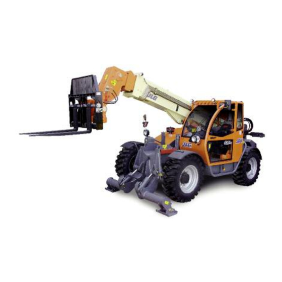
- Page 1 Operation & Safety Manual Original Instructions Keep this manual with machine at all times. Models 3508PS, 3509PS, 3512PS, 3513PS, 4008PS, 4009PS, 4012PS, 4013PS, 4017PS 31200205 Revised March 31, 2017 An Oshkosh Corporation Company...
- Page 3 Revision Log Revision Log REVISION LOG August 10, 2007 - A - Original Issue of Manual December 12, 2007 - B - Added platform information. Revised pages c, 2-5, 3-2, 3-3, 3-5, 3-8, 3-9, 3-14, 3-16, 3-22, 4-1, 4-3, 5-10, 5-11, 5-30, 6-2, 6-3, 7-18, 7-19, 8-5, 9-1 &...
-
Page 4: Read This First
Read This First Read This First This manual is a very important tool! Keep it with the machine at all times. The purpose of this manual is to provide owners, users, operators, lessors, and lessees with the precautions and operating procedures essential for the safe and proper machine operation for its intended purpose. - Page 5 Read This First This product must comply with all safety related bulletins. Contact JLG Industries, Inc. or the local authorized JLG representative for information regarding safety- related bulletins which may have been issued for this product. JLG Industries, Inc. sends safety related bulletins to the owner of record of this machine.
-
Page 6: Other Publications Available
Read This First Other Publications Available Service Manual....................31200206 Illustrated Parts Manual................31200204 Load Management Indicator System Operation & Safety Manual (if equipped)................Contact JLG Platform for 3513PS, 4013PS & 4017PS Operation & Safety Manual (if equipped for platform) ..........Contact JLG Note: The following standards may be referenced in this manual: ANSI is compliant to ANSI/ITSDF B56.6 AUS is compliant to AS 1418.19 CE is compliant to EN1459... -
Page 7: Table Of Contents
Table of Contents Table of Contents TABLE OF CONTENTS Revision Log Read This First Operator Qualifications ............b Modifications ..............b Other Publications Available ..........d Table of Contents Section 1 - General Safety Practices 1.1 Hazard Classification System ..........1-1 Safety Alert System and Safety Signal Words ....1-1 1.2 General Precautions ............1-1 1.3 Operation Safety ..............1-2... - Page 8 Table of Contents Section 3 - Controls and Indicators 3.1 General................3-1 3.2 Controls ................3-2 Instrument Panel ............3-4 Display Screen ............... 3-6 Keypad ................3-8 Ignition ................3-10 Park Brake..............3-11 Parking Procedure............3-11 Transmission Control Lever.......... 3-12 Load Stability Indicator (LSI) ........
- Page 9 Table of Contents Section 4 - Operation 4.1 Engine..................4-1 Starting the Engine ............4-1 Battery Boosted Starting ..........4-2 Normal Engine Operation ..........4-3 Shut-Down Procedure.............4-3 4.2 Operating with a Non-Suspended Load.......4-4 Lift Load Safely ...............4-4 Picking Up a Load ............4-4 Transporting a Load............4-5 Leveling Procedure ............4-5 Placing a Load ..............4-6 Disengaging a Load ............4-6...
- Page 10 Table of Contents Section 5 - Attachments and Hitches 5.1 Approved Attachments ............5-1 5.2 Unapproved Attachments............ 5-1 5.3 JLG Supplied Attachments..........5-2 3508PS, 3509PS, 3512PS, 4008PS, 4009PS & 4012PS ............... 5-2 3513PS, 4013PS & 4017PS........... 5-3 5.4 Telehandler/Attachment/Fork Capacity ....... 5-6 5.5 Use of the Capacity Chart ...........
- Page 11 Table of Contents Section 6 - Emergency Procedures 6.1 Towing a Disabled Product ..........6-1 Moving Short Distances ..........6-1 Moving Longer Distances ..........6-1 6.2 Emergency Lowering of Boom..........6-2 6.3 Emergency Lowering of Boom If Equipped for Platform ..6-3 Auxiliary Power System ..........6-3 6.4 Cab Emergency Exit ............6-4 Section 7 - Lubrication and Maintenance 7.1 Introduction ................7-1...
- Page 12 Table of Contents Section 9 - Specifications 9.1 Product Specifications............9-1 Fluid and Lubrication Capacities ........9-1 Tires................9-2 Performance ..............9-3 Dimensions..............9-6 Declaration of Vibration (CE).......... 9-8 Noise Emission Level (CE)..........9-8 Index Inspection, Maintenance and Repair Log 31200205...
-
Page 13: Section 1 - General Safety Practices
Section 1 - General Safety Practices SECTION 1 - GENERAL SAFETY PRACTICES HAZARD CLASSIFICATION SYSTEM Safety Alert System and Safety Signal Words DANGER OW0010 DANGER indicates an imminently hazardous situation which, if not avoided, will result in death or serious injury. WARNING OW0021 WARNING indicates a potentially hazardous situation which, if not avoided, could... -
Page 14: Operation Safety
Section 1 - General Safety Practices OPERATION SAFETY Electrical Hazards 10 FT (3 M) OW0040 • This machine is not insulated and does not provide protection from contact or being near electrical current. • NEVER operate the telehandler in an area where overhead power lines, overhead or underground cables, or other power sources may exist without ensuring the appropriate power or utility company de-energizes the lines. -
Page 15: Tip Over Hazard
Section 1 - General Safety Practices Tip Over Hazard General • For additional load requirements, refer to the appropriate capacity chart. OW0050 • Never use an attachment without the appropriate JLG approved capacity chart installed on the telehandler. • Understand how to properly use the capacity charts located in cab. •... - Page 16 Section 1 - General Safety Practices OH2291 • MAINTAIN proper tire pressure at all times. If proper tire pressures are not maintained, this machine could tip over. • Refer to manufacturer’s specifications for proper fill ratio and pressure requirements for tires equipped with ballast. OH20911 •...
- Page 17 Section 1 - General Safety Practices Non-Suspended Load OW0060 • DO NOT drive with boom raised. Suspended Load OW0150 • Tether suspended loads to restrict movement. • Weight of all rigging (slings, etc.) must be included as part of load. •...
-
Page 18: Travel Hazard
Section 1 - General Safety Practices Travel Hazard 2-Wheel Front Steer 4-Wheel Circle Steer 4-Wheel Crab Steer OAL2030 • Steering characteristics differ between steer modes. Identify the steer mode settings of the telehandler being operated. • DO NOT change steer modes while traveling. Steer modes must be changed while telehandler is stationary. -
Page 19: Load Falling Hazard
Section 1 - General Safety Practices Load Falling Hazard OW0130 • Never suspend load from forks or other parts of carriage. • DO NOT burn or drill holes in fork(s). • Forks must be centered under load and spaced apart as far as possible. 31200205... -
Page 20: Lifting Personnel
Section 1 - General Safety Practices Lifting Personnel OW0170 • When lifting personnel, USE ONLY a JLG approved personnel work platform, with proper capacity chart displayed in the cab. OW0190 • DO NOT drive machine from cab when personnel are in platform. 31200205... -
Page 21: Driving Hazards On Slopes
Section 1 - General Safety Practices Driving Hazards on Slopes OW0200 To maintain sufficient traction and braking capabilities, travel on slopes as follows: • When unloaded, the rear of the machine is the “heavy end.” Drive with forks pointed downhill. •... -
Page 22: Pinch Points And Crush Hazards
Section 1 - General Safety Practices Pinch Points and Crush Hazards Stay clear of pinch points and rotating parts on the telehandler. OW0210 • Stay clear of moving parts while engine is running. OW0220 • Keep clear of steering tires and frame or other objects. OW0230 •... - Page 23 Section 1 - General Safety Practices OW0240 • Keep clear of boom holes. OW0250 • Keep arms and hands clear of attachment tilt cylinder. OW0260 • Keep hands and fingers clear of carriage and forks. OW0960 • Keep others away while operating. 31200205 1-11...
-
Page 24: Fall Hazard
Section 1 - General Safety Practices Fall Hazard OW0280 • Enter using the proper hand holds and steps provided. Always maintain 3-point contact when mounting or dismounting. Never grab control levers or steering wheel when mounting or dismounting the machine. •... -
Page 25: Chemical Hazards
Section 1 - General Safety Practices Chemical Hazards Exhaust Fumes • DO NOT operate machine in an enclosed area without proper ventilation. • DO NOT operate the machine in hazardous environments unless approved for that purpose by JLG and site owner. Sparks from the electrical system and the engine exhaust can cause an explosion. - Page 26 Section 1 - General Safety Practices This Page Intentionally Left Blank 1-14 31200205...
-
Page 27: Section 2 - Pre-Operation And Inspection
Section 2 - Pre-Operation and Inspection SECTION 2 - PRE-OPERATION AND INSPECTION PRE-OPERATION CHECK AND INSPECTION Note: Complete all required maintenance before operating unit. WARNING FALL HAZARD. Use extreme caution when checking items beyond your normal reach. Use an approved ladder. The pre-operation check and inspection, performed at beginning of each work shift or at each change of operator, should include the following: 1. - Page 28 Section 2 - Pre-Operation and Inspection 8. Operational Check - Once the walk-around inspection is complete, perform a warm-up and operational check (see page 2-8) of all systems in an area free of overhead and ground level obstructions. See Section 3 - Controls and Indicators for more specific operating instructions.
-
Page 29: Safety Decals
Section 2 - Pre-Operation and Inspection SAFETY DECALS Ensure all DANGER, WARNING, CAUTION and instructional decals and proper capacity charts are legible and in place. Clean and replace as required. 8005616 8008657 8008657 8005616 8005675 OPTIONAL 2999964 (40) 8009377 (35) 3700016 2603207 (20) 8009890 (22) - Page 30 Section 2 - Pre-Operation and Inspection 8005675 8008657 8008657 8005616 8005616 1001094171 (AUS) 3700016 Optional 2999964 (40) 8009377 (35) 2603207 (20) 8009890 (22) 8009885 (12) A - 1706753 3700016 3700016 B - 1706754 1001094708B 8005617 1001094708 C - 1706755 D - 1706756 (12, 13 & 17M) E - 1706757 (12, 13 &...
- Page 31 Section 2 - Pre-Operation and Inspection 1001094900 (LIFT PATTERN) 1001094713 1001094900B 1001094713A 1001094901 1001094902 (LOADER PATTERN) (12, 13 & 17M) LOAD CHARTS 4017 P/N 1170001 P/N 2340029 P/N 4802111 P/N 8008014 70° 60° 50° 40° 30° 20° 1001094901B 1001094902B 10° 0°...
-
Page 32: Walk-Around Inspection
Section 2 - Pre-Operation and Inspection WALK-AROUND INSPECTION OZ2152 Begin your walk-around inspection at item 1, as noted below. Continue to your right (counterclockwise when viewed from top) checking each item in sequence. INSPECTION NOTE: On all components, make sure there are no loose or missing parts, that they are securely fastened and no visible leaks or excessive wear exists in addition to any other criteria mentioned. - Page 33 Section 2 - Pre-Operation and Inspection 6. Work Lights (if equipped) - Clean and undamaged. 7. Mirrors - Clean and undamaged. 8. Cab and Electrical - • General appearance; no visible damage. • Frame level indicator(s) and window glass undamaged and clean. •...
-
Page 34: Warm-Up And Operational Checks
Section 2 - Pre-Operation and Inspection WARM-UP AND OPERATIONAL CHECKS Warm-Up Check During warm-up period, check: 1. Heater, defroster and windshield wiper (if equipped). 2. Check all lighting systems (if equipped) for proper operation. 3. Adjust mirror(s) for maximum visibility. WARNING CUT/CRUSH/BURN HAZARD. -
Page 35: Operator Cab
Section 2 - Pre-Operation and Inspection OPERATOR CAB The telehandler is equipped with an enclosed ROPS/FOPS cab. WARNING CRUSH HAZARD. Never operate telehandler unless the overhead guard and cab structure are in good condition. Any modification to this machine must be approved by JLG to assure compliance with ROPS/FOPS certification for this cab/machine configuration. -
Page 36: Windows
Section 2 - Pre-Operation and Inspection WINDOWS Keep all windows clean and unobstructed. Cab Door Window OZ0211 • Cab door (1) must be closed during operation. • During operation the cab door window (2) must either be latched open or closed. •... -
Page 37: Section 3 - Controls And Indicators
Section 3 - Controls and Indicators SECTION 3 - CONTROLS AND INDICATORS GENERAL This section provides the necessary information needed to understand control functions. Note: The manufacturer has no direct control over machine application and operation. The user and operator are responsible for conforming with good safety practices. -
Page 38: Controls
Section 3 - Controls and Indicators CONTROLS OZ2283 1. Park Brake: See page 3-11. 2. Accelerator Pedal: Pressing down the pedal increases engine and hydraulic speed. 3. Service Brake Pedal: The further the pedal is depressed, the slower the travel speed. - Page 39 Section 3 - Controls and Indicators 9. Frame Level Indicator: Enables operator to determine the left to right level condition of the telehandler. 10. Steering Column Adjuster: See page 3-17. 11. Steering Wheel: Turning the steering wheel to the left or right steers the machine in the corresponding direction.
-
Page 40: Instrument Panel
Section 3 - Controls and Indicators Instrument Panel OZ2061 1. Low Fuel Indicator: Illuminates and buzzer sounds briefly when fuel level is low. 2. Fuel Gauge: Indicates amount of fuel in fuel tank. 3. Left Turn Signal Indicator: Illuminates when left turn signal is active. 4. - Page 41 Section 3 - Controls and Indicators 16. System Distress Indicator: Illuminates and buzzer sounds when critical machine and engine faults exist. 17. Engine Fault Critical Indicator: Illuminates and buzzer sounds when a critical engine fault exists. 18. Engine Fault Warning Indicator: Illuminates and buzzer sounds when engine is operating outside the normal range.
-
Page 42: Display Screen
Section 3 - Controls and Indicators Display Screen DISPLAY SHOWN WITH CONTINUOUS DISPLAY SHOWN WITH ANTI THEFT AUXILIARY HYDRAULICS ACTIVE ACTIVE AT SYSTEM START 0000 0000 0000 0000 km/h km/h OAH1270 1. Joystick Mode: Displays current joystick mode. Joystick mode can be changed by the machine owner in Operator Tools Menu (level 2 password required). - Page 43 Section 3 - Controls and Indicators 8. Anti Theft Code Entry: If active, the four digit code must be entered after system start. See “Anti Theft” on page 3-25 for details. MENU: HELP: PRESS ENTER OAH2000 9. Menus: Menus display fault codes and other machine information while allowing modification of some operating parameters.
-
Page 44: Keypad
Section 3 - Controls and Indicators Keypad OZ2361 1. C (Clear or escape): Use in conjuction with display screen. Returns user interface one level during navigation. If at top level menu, depress and hold for one second to exit. 2. Up/Down Arrows: Use in conjuction with display screen. Navigate menu selections and change adjustable values. - Page 45 Section 3 - Controls and Indicators This Page Intentionally Left Blank 31200205...
-
Page 46: Ignition
Section 3 - Controls and Indicators Ignition OZ2300 • Position 0 - Engine off. • Position I - Voltage available for all electrical functions. • Position II - Engine preheat at temperatures below 0° C (32° F). Wait to start engine until preheat indicator on instrument panel goes out. -
Page 47: Park Brake
Section 3 - Controls and Indicators Park Brake OZ2290 8, 9, 12 & 13M The park brake lever (1) controls the application and release of the park brake. • Pull lever back to apply park brake. • Squeeze release (2) or lift detent ring (3) and push lever forward to release park brake. -
Page 48: Transmission Control Lever
Section 3 - Controls and Indicators Transmission Control Lever Direction of Travel Selection OZ2310 Transmission control lever (1) engages forward or reverse travel. • Push lever forward for forward travel; pull lever rearward for reverse travel. Move lever to centered position for Neutral. •... - Page 49 Section 3 - Controls and Indicators Gear Selection OZ2320 Gear selection is located on the twist grip handle (2) of transmission control lever. • Twist hand grip to select gear. • Select the appropriate gear for the task being performed. Use a lower gear when transporting a load.
-
Page 50: Load Stability Indicator (Lsi)
Section 3 - Controls and Indicators Load Stability Indicator (LSI) WARNING TIP OVER HAZARD. The LSI considers only longitudinal stability limitations, observe all operating parameters. Failure to follow operating parameters of the telehandler could damage the equipment and/or cause tip over. 8, 9, 12 &... - Page 51 Section 3 - Controls and Indicators 8, 9, 12 & 13M S/N 1160005993 & After including 1160005949 & 1160005950 17M S/N 1160005937 & After excluding 1160005952, 1160005960, 1160005963, 1160005966 & 1160005978 OZ3711 The LSI (9) provides visual and audible indication of forward stability limitations when machine is static on firm, level surface.
- Page 52 Section 3 - Controls and Indicators • Travel in accordance with the requirements set forth in Section 1 - General Safety Practices. • Test LSI (14) at the beginning of each work shift. See Section 8 - Additional Checks. • When placing a load, ensure axles are not fully steered in either direction. WARNING TIP OVER HAZARD.
-
Page 53: Steering Column Adjuster
Section 3 - Controls and Indicators Steering Column Adjuster OZ2330 • Follow “Shut-Down Procedure” on page 4-3. • Turn lever (1) counterclockwise to unlock. • Place steering column in desired position. • Turn lever clockwise to lock. WARNING TIP OVER/CRUSH HAZARD. Bring telehandler to a complete stop before shifting transmission control lever. -
Page 54: Joystick
Section 3 - Controls and Indicators Joystick Lift Joystick Pattern OAH1351 Verify the lift joystick pattern icon (2) is active on the display (1) and the joystick decal located inside the cab matches the machine controls. 12, 13 & 17M OZ2490 The joystick (1) controls the boom, attachment, auxiliary hydraulics and outrigger functions. - Page 55 Section 3 - Controls and Indicators WARNING TIP OVER/CRUSH HAZARD. Rapid, jerky operation of controls will cause rapid, jerky movement of the load. Such movements could cause the load to shift or fall or could cause the machine to tip over. Attachment Functions Attachment tilt is controlled by the roller switch (2).
- Page 56 Section 3 - Controls and Indicators Loader Joystick Pattern OAH1381 Verify the loader joystick pattern icon (3) is active on the display (1) and the joystick decal located inside the cab matches the machine controls. 12, 13 & 17M OZ2500 The joystick (1) controls the boom, attachment, auxiliary hydraulics and outrigger functions.
- Page 57 Section 3 - Controls and Indicators WARNING TIP OVER/CRUSH HAZARD. Rapid, jerky operation of controls will cause rapid, jerky movement of the load. Such movements could cause the load to shift or fall or could cause the machine to tip over. Attachment Functions Attachment tilt is controlled by the joystick.
-
Page 58: Armrest And Right Hand Console
Section 3 - Controls and Indicators Armrest and Right Hand Console OZ2420 1. Frame Level Switch (if equipped): Controls the left to right frame level. Depress right side of switch to rotate frame right; depress left side of switch to rotate frame left. - Page 59 Section 3 - Controls and Indicators 13. Continuous Auxiliary Hydraulics Switch: a. Depress and release front of switch for continuous operation of hydraulic powered attachments. Set continuous auxiliary hydraulic level (-100% to 100%) within 10 seconds using the keypad up/down arrow buttons (see page 3-8).
-
Page 60: Accessory Control Lever
Section 3 - Controls and Indicators Accessory Control Lever Turn Signals and Low/High Beam Headlights OZ3450 • Push accessory control lever (1) forward (2) to activate left turn signal. • Pull lever backward (3) to activate right turn signal. • The lever must be manually returned to the center position to deactivate either turn signal. -
Page 61: Anti Theft
Section 3 - Controls and Indicators ANTI THEFT Machines with the anti theft feature active require entering a numeric code before operation to prevent unauthorized use. Code entry is accomplished using the display and keypad. 0000 0000 km/h OAH1430 1. Turn ignition switch to position I. If anti theft is active, the display (1) will prompt the operator for a numeric code. -
Page 62: Steer Modes
Section 3 - Controls and Indicators STEER MODES Three steer modes are available for operator use. 2-Wheel Front Steer 4-Wheel Circle Steer 4-Wheel Crab Steer OAL2030 Note: 2-Wheel Front Steer mode is required for travel on public roads. Manual Steering Alignment Mode Change If manual steering alignment mode is active under the Operator Tools menu (see page 3-7), use the following procedure for steer mode change. -
Page 63: All Wheel Assisted Steering Alignment Mode Change
Section 3 - Controls and Indicators All Wheel Assisted Steering Alignment Mode Change If all wheel assisted steering alignment mode is active under the Operator Tools menu (see page 3-7), use the following procedure for steer mode change. 1. Bring machine to a stop using service brake. OAM2381 2. -
Page 64: Operator Seat
Section 3 - Controls and Indicators OPERATOR SEAT Adjustments Prior to starting the engine adjust seat for position and comfort. Mechanical Suspension Seat OAH1471 1. Backrest: Use handle to adjust backrest angle. 2. Fore/Aft: Use handle to move seat fore and aft. 3. - Page 65 Section 3 - Controls and Indicators Pneumatic Suspension Seat OAH1481 1. Backrest Angle: Use handle to adjust backrest angle. 2. Fore/Aft: Use handle to move seat fore and aft. 3. Suspension: Use knob to adjust suspension to the appropriate weight setting. 4.
-
Page 66: Seat Belt
Section 3 - Controls and Indicators Seat Belt OH20912 Fasten seat belt as follows: 1. Grasp both free ends of the belt making certain that belt webbing is not twisted or entangled. 2. With back straight in the seat, couple the retractable end (male end) of the belt into the receptacle (buckle) end of the belt. -
Page 67: Boom Indicators
Section 3 - Controls and Indicators BOOM INDICATORS OZ2411 Boom Extension • The boom extension indicators (1) are located on the left side of the boom. Use these indicators to determine boom extension when using the capacity chart (see “Use of the Capacity Chart” on page 5-7). Boom Angle (AUS) •... - Page 68 Section 3 - Controls and Indicators This Page Intentionally Left Blank 3-32 31200205...
-
Page 69: Section 4 - Operation
Section 4 - Operation SECTION 4 - OPERATION ENGINE Starting the Engine This machine can be operated under normal conditions in temperatures of -18°C to 45°C (0°F to 113°F). Consult JLG for operation outside this range or under abnormal conditions. 1. -
Page 70: Battery Boosted Starting
Section 4 - Operation Battery Boosted Starting OW0530 If battery-boost starting (jump-start) is necessary, proceed as follows: • Never allow vehicles to touch. • Ensure boosting vehicle engine is running. • Connect the positive (+) jumper cable to positive (+) post of discharged battery. •... -
Page 71: Normal Engine Operation
Section 4 - Operation Normal Engine Operation • Observe instrument panel and display frequently to be sure all systems are functioning properly. • Be alert for unusual noises or vibration. When an unusual condition is noticed, park machine in safe position and perform shut-down procedure. Report condition to your supervisor or maintenance personnel. -
Page 72: Operating With A Non-Suspended Load
Section 4 - Operation OPERATING WITH A NON-SUSPENDED LOAD Lift Load Safely • You must know the weight and load center of every load you lift. If you are not sure of the weight and load center, check with your supervisor or with the supplier of the material. -
Page 73: Transporting A Load
Section 4 - Operation Transporting a Load OW0540 • After engaging the load and resting it against the backrest, tilt the load back to position it for travel. Travel in accordance with the requirements set forth in Section 1 - General Safety Practices and Section 5 - Attachments and Hitches. Leveling Procedure 1. -
Page 74: Placing A Load
Section 4 - Operation Placing a Load Before placing any load be sure that: • The landing point can safely support the weight of the load. • The landing point is level; front to back and side to side. • Use the capacity chart to determine safe boom extension range. See “Use of the Capacity Chart”... -
Page 75: Operating With A Suspended Load
Section 4 - Operation OPERATING WITH A SUSPENDED LOAD Lift Load Safely • You must know the weight and load center of every load you lift. If you are not sure of the weight and load center, check with your supervisor or with the supplier of the material. -
Page 76: Transporting A Suspended Load
Section 4 - Operation Transporting a Suspended Load OZ3160 OW0130 • Travel in accordance with the requirements set forth in Section 1 - General Safety Practices and Section 5 - Attachments and Hitches. • For additional requirements, refer to the appropriate capacity chart in the operator cab. -
Page 77: Placing A Suspended Load
Section 4 - Operation Placing a Suspended Load Before placing any load be sure that: • The landing point can safely support the weight of the load. • The landing point is level; front to back and side to side. •... -
Page 78: Road Operation (Ce)
Section 4 - Operation ROAD OPERATION (CE) 1. Preparation a. Remove load from attachment. b. Remove any large amounts of dirt from machine. c. Check lights and mirrors and adjust if necessary. Note: Be sure to follow all local and federal/provincial traffic regulations. 2. -
Page 79: Loading And Securing For Transport
Section 4 - Operation LOADING AND SECURING FOR TRANSPORT OZ2180 Tiedown 1. If equipped, level the telehandler prior to loading. 2. Using a spotter, load the telehandler with boom as low as possible. 3. Once loaded, apply parking brake and lower boom until boom or attachment is resting on deck. -
Page 80: Lifting
Section 4 - Operation Lifting • When lifting machine, it is very important that the lifting device and equipment is attached only to designated lifting points. If machine is not equipped with lifting lugs contact JLG Product Safety for information. •... -
Page 81: Section 5 - Attachments And Hitches
Section 5 - Attachments and Hitches SECTION 5 - ATTACHMENTS AND HITCHES APPROVED ATTACHMENTS To determine if an attachment is approved for use on the specific telehandler you are using, perform the following prior to installation. • The attachment model/option number on the attachment identification plate must match the attachment number on a capacity chart located in the operator cab. -
Page 82: Jlg Supplied Attachments
Section 5 - Attachments and Hitches JLG SUPPLIED ATTACHMENTS 3508PS, 3509PS, 3512PS, 4008PS, 4009PS & 4012PS Applicable Standard 3508PS 3509PS 3512PS 4008PS 4009PS 4012PS Part Attachment Number Carriage, 1185 mm 1170028 Carriage, 1185 mm 1001107333 Carriage, 1185 mm 1001107581 Side Shift Carriage, 1200 mm 1170002 Fork, 50x100x1200 mm 2340030... -
Page 83: 3513Ps, 4013Ps & 4017Ps
Section 5 - Attachments and Hitches 3513PS, 4013PS & 4017PS Applicable Standard Quick 3513PS Attach 4017PS 4013PS Part Attachment Number CE AUS CE AUS JLG Manitou Carriage, 1185 mm 1170028 Carriage, 1185 mm 1001107333 Carriage, 1185 mm 1001107581 Carriage, 1200 mm 1001102553 Side Shift Carriage, 1200 mm 1170002... - Page 84 Section 5 - Attachments and Hitches Applicable Standard Quick 3513PS Attach 4017PS 4013PS Part Attachment Number CE AUS CE AUS JLG Manitou 1001097355 Platform, 4,5 m 1001112108 1001114462 31200205...
- Page 85 Section 5 - Attachments and Hitches This Page Intentionally Left Blank 31200205...
-
Page 86: Telehandler/Attachment/Fork Capacity
Section 5 - Attachments and Hitches TELEHANDLER/ATTACHMENT/FORK CAPACITY OZ0810 Prior to installing the attachment verify it is approved and the telehandler is equipped with the proper capacity chart. See “Approved Attachments” on page 5-1. To determine the maximum capacity of the telehandler and attachment, use the smallest of the following capacities: •... -
Page 87: Use Of The Capacity Chart
Section 5 - Attachments and Hitches USE OF THE CAPACITY CHART To properly use the capacity chart (see page 5-8), the operator must first determine and/or have the following: 1. An approved attachment. See “Approved Attachments” on page 5-1. 2. The proper Capacity Chart. 3. -
Page 88: Sample Capacity Chart (Ce)
Section 5 - Attachments and Hitches Sample Capacity Chart (CE) This Capacity Chart may be used with this model ONLY. These numbers must match the The telehandler model is indicated on the boom or chassis. model/option number stamped Model XXXX is used for demonstration purposes only. on the attachment ID Plate. - Page 89 Section 5 - Attachments and Hitches To identify the proper capacity chart on telehandlers equipped with outriggers, refer to the following icons which may be located on the capacity chart. • Use when lifting a load with outriggers up. OW0930 •...
-
Page 90: Sample Capacity Chart (Aus)
Section 5 - Attachments and Hitches Sample Capacity Chart (AUS) This Capacity Chart may be used with this model ONLY. The telehandler model is indicated on the boom or chassis. These numbers must match the Model XXXX is used for model/option number stamped demonstration purposes only. - Page 91 Section 5 - Attachments and Hitches To identify the proper capacity chart on telehandlers equipped with outriggers, refer to the following icons which may be located on the capacity chart. • Use when lifting a load with outriggers up. OW0930 •...
-
Page 92: Example
Section 5 - Attachments and Hitches Example A contractor owns a model xxxx telehandler with a fork carriage. He knows this attachment may be used with his model since: • The attachment model/option number, matches the attachment number on the capacity chart. -
Page 93: Attachment Installation
Section 5 - Attachments and Hitches ATTACHMENT INSTALLATION JLG Quick Attach MECHANICAL HYDRAULIC OZ3470 1. Attachment 2. Attachment Pin Recess 3. Attachment Pin 4. Lock Pin 5. Retainer Pin (mechanical quick attach) 6. Quick Attach (attachment tilt control in cab, see page 3-18 for details) WARNING CRUSH HAZARD. - Page 94 Section 5 - Attachments and Hitches Mechanical Quick Attach This installation procedure is designed for one-person operation. Prior to exiting cab, perform “Shut-Down Procedure” on page 4-3. 1. Tilt quick attach forward to provide clearance. Check to be sure lock pin is out. OZ3480 2.
- Page 95 Section 5 - Attachments and Hitches Manual Hydraulic Quick Attach This installation procedure is designed for one-person operation. Prior to exiting cab, perform “Shut-Down Procedure” on page 4-3. 1. Turn auxiliary hydraulic valve handle (1) back, toward the operator cab, to enable hydraulic quick attach function.
- Page 96 Section 5 - Attachments and Hitches OAL1930 6. Raise boom to eye level and visually check that the lock pin protrudes through the hole. If the pin does not protrude through the hole, place the attachment on the ground and return to step 2. DISENGAGED ENGAGED 7.
- Page 97 Section 5 - Attachments and Hitches Hydraulic Quick Attach This installation procedure is designed for one-person operation. 1. Tilt quick attach forward to provide clearance. Check to be sure lock pin is disengaged. OZ3580 2. Align attachment pin with recess in attachment. Raise boom slightly to engage attachment pin in recess.
-
Page 98: Manitou Quick Attach
Section 5 - Attachments and Hitches Manitou Quick Attach OZ3610 1. Attachment 2. Attachment Pin 3. Attachment Pin Recess 4. Lock Pin 5. Retainer Pin (mechanical quick attach) 6. Manitou Quick Attach (attachment tilt control in cab, see page 3-18 for details) WARNING CRUSH HAZARD. - Page 99 Section 5 - Attachments and Hitches This installation procedure is designed for one-person operation. Prior to exiting cab, perform “Shut-Down Procedure” on page 4-3. 1. Tilt quick attach forward to provide clearance. Check to be sure lock pin is out. OZ3620 2.
-
Page 100: Hydraulic Operated Attachment
Section 5 - Attachments and Hitches Hydraulic Operated Attachment OZ2220 OZ0632 1. Install attachment (see page 5-13 or 5-18). 2. Lower attachment to ground. 3. Quickly depress and release continuous auxiliary hydraulics switch (1) twice. Depress again and hold to relieve pressure at both auxiliary fittings (2). Note: Depressing of auxiliary hydraulics switch three times must be accomplished within two seconds. -
Page 101: Adjusting/Moving Forks
Section 5 - Attachments and Hitches ADJUSTING/MOVING FORKS Carriages may have different locations where forks can be positioned. Two different methods can be used for repositioning, depending upon the carriage structure. Note: Apply a light coating of appropriate lubricant to ease sliding of forks or fork bar. -
Page 102: Attachment Operation
Section 5 - Attachments and Hitches ATTACHMENT OPERATION • Capacities and range limits for the telehandler change depending on the attachment in use. • Separate attachment instructions must be kept in Manual Holder in cab with this Operation & Safety Manual. An additional copy must be kept with the attachment if it is equipped with a manual holder. -
Page 103: Carriage W/Forks
Section 5 - Attachments and Hitches Carriage w/Forks Use Carriage Capacity Chart To determine maximum capacity, refer to “” on page 5-5. OZ0770 OZ2200 The joystick (1) controls movement of the boom. The attachment tilt roller switch (2) controls carriage tilt. •... -
Page 104: Side Shift Carriage
Section 5 - Attachments and Hitches Side Shift Carriage Use Side Shift Carriage Capacity Chart To determine maximum capacity, refer to “” on page 5-5. OAL1540 OZ2200 The joystick (1) controls movement of the boom. The attachment tilt roller switch (2) controls carriage tilt. •... - Page 105 Section 5 - Attachments and Hitches • Press and hold button (3) to shift forks right or press and hold button (4) to shift forks left. • While pressing and holding button (5), move joystick forward to shift forks right or move joystick back to shift forks left.
-
Page 106: Fork Positioning Carriage
Section 5 - Attachments and Hitches Fork Positioning Carriage Use Fork Positioning Carriage Load Chart To determine maximum capacity, refer to “” on page 5-5. OZ3670 OZ2200 The joystick (1) controls movement of the boom. The attachment tilt roller switch (2) controls carriage tilt. •... - Page 107 Section 5 - Attachments and Hitches • Press and hold button (3) to shift forks out or press and hold button (4) to shift forks in. • While pressing and holding button (5), move joystick forward to shift forks out or move joystick back to shift forks in.
-
Page 108: Fork Extension
Section 5 - Attachments and Hitches Fork Extension Use Appropriate Carriage Capacity Chart To determine maximum capacity of the carriage, refer to “” on page 5-5. OZ0750 Note: The maximum capacity of the carriage when equipped with fork extensions may be reduced to the capacity indicated on the fork extensions. If the load exceeds the capacity of the fork extension contact JLG to obtain forks and/or fork extensions of the proper load rating and length. - Page 109 Section 5 - Attachments and Hitches Equipment Damage Precautions • The heavy part of the load must be against the carriage backrest. • Do not allow load center of gravity to be in front of tip of the supporting fork. •...
-
Page 110: Fork Mounted Hook
Section 5 - Attachments and Hitches Fork Mounted Hook Use Fork Mounted Hook Capacity Chart To determine maximum capacity, refer to “” on page 5-5. OY0640 Suspend loads in accordance with requirements set forth in Section 1 - General Safety Practices. OZ2590 The joystick (1) controls movement of the boom. - Page 111 Section 5 - Attachments and Hitches Operation: • Pallet or lumber forks of an appropriate load rating must be used. Do not use with cubing or block forks. • Weight of rigging must be included as part of total load being lifted. •...
-
Page 112: Quick Attach Mounted Hook
Section 5 - Attachments and Hitches Quick Attach Mounted Hook Use Quick Attach Mounted Hook Capacity Chart To determine maximum capacity, refer to “” on page 5-5. OAL1510 Suspend loads in accordance with requirements set forth in Section 1 - General Safety Practices. OZ2600 The joystick (1) controls movement of the boom. -
Page 113: Truss Boom
Section 5 - Attachments and Hitches Truss Boom Use Appropriate Truss Boom Capacity Chart To determine maximum capacity, refer to “” on page 5-5. OZ0780 Suspend loads in accordance with requirements set forth in Section 1 - General Safety Practices. OZ2510 The joystick (1) controls movement of the boom. -
Page 114: Bucket
Section 5 - Attachments and Hitches Bucket Use Appropriate Bucket Capacity Chart To determine maximum capacity, refer to “” on page 5-5. OZ0730 OZ2210 The joystick (1) controls movement of the boom. The attachment tilt roller switch (2) controls bucket tilt. •... - Page 115 Section 5 - Attachments and Hitches Operation: • Raise or lower boom to appropriate height for loading material from stockpile. • Align telehandler with face of stockpile and drive slowly and smoothly into pile to load bucket. • Tilt bucket up far enough to retain load and back away from pile. •...
-
Page 116: Multi-Purpose Bucket
Section 5 - Attachments and Hitches Multi-Purpose Bucket Use Appropriate Bucket Capacity Chart To determine maximum capacity, refer to “” on page 5-5. OZ2540 OZ2210 The joystick (1) controls movement of the boom. The attachment tilt roller switch (2) controls bucket tilt. •... - Page 117 Section 5 - Attachments and Hitches To open/close bucket: Press and hold button (3) to close bucket or press and hold button (4) to open bucket. While pressing and holding button (5), move joystick forward to close bucket or move joystick back to open bucket. Installation Procedure: •...
-
Page 118: Grapple Bucket
Section 5 - Attachments and Hitches Grapple Bucket Use Appropriate Bucket Capacity Chart To determine maximum capacity, refer to “” on page 5-5. OZ1450 OZ2210 The joystick (1) controls movement of the boom. The attachment tilt roller switch (2) controls bucket tilt. •... - Page 119 Section 5 - Attachments and Hitches To Open/Close Grapple: Press and hold button (3) to close grapple or press and hold button (4) to open grapple. While pressing and holding button (5), move joystick forward to close grapple or move joystick back to open grapple. Installation Procedure: •...
-
Page 120: Concrete Bucket - Fork Mounted
Section 5 - Attachments and Hitches Concrete Bucket - Fork Mounted Use Appropriate Carriage Capacity Chart To determine maximum capacity, refer to “” on page 5-5. OZ2560 OZ2570 The joystick (1) controls movement of the boom. The attachment tilt roller switch (2) controls bucket tilt. •... - Page 121 Section 5 - Attachments and Hitches To open/close bucket gate: Press and hold button (3) to close bucket gate or press and hold button (4) to open bucket gate. While pressing and holding button (5), move joystick forward to close bucket gate or move joystick back to open bucket gate.
-
Page 122: Platform
Section 5 - Attachments and Hitches Platform Use Platform Capacity Chart To determine maximum capacity, refer to capacity decal on platform. OZ2870 OZ2880 The joystick (1) controls movement of the boom. The attachment tilt roller switch (2) controls platform tilt. •... -
Page 123: Hitches (3508Ps, 4008Ps, 3509Ps & 4009Ps)
Section 5 - Attachments and Hitches HITCHES (3508PS, 4008PS, 3509PS & 4009PS) Machines may be equipped with various types of hitches. Maximum towing capacity shall be the smallest of the telehandler and hitch capacities. Refer to local governmental regulations for additional towing requirements and/or restrictions. -
Page 124: Pin Hitch - Cuna D2 (Italy)
Section 5 - Attachments and Hitches Pin Hitch - CUNA D2 (Italy) Maximum combined weight of trailer and load ......12 000 kg (26 450 lb) Maximum vertical weight at hitch interface........2000 kg (4400 lb) OAM2450 Connecting trailer for towing: 1. -
Page 125: Pin Hitch
Section 5 - Attachments and Hitches Pin Hitch Maximum combined weight of trailer and load ......12 000 kg (26 450 lb) Maximum vertical weight at hitch interface........2500 kg (5500 lb) OAM2460 Connecting trailer for towing: 1. Remove safety pin (1) and pull pin (2) from hitch (3). 2. -
Page 126: Auto Hitch
Section 5 - Attachments and Hitches Auto Hitch Maximum combined weight of trailer and load ......12 000 kg (26 450 lb) Maximum vertical weight at hitch interface........2500 kg (5500 lb) OAM2470 Connecting trailer for towing: 1. Rotate lever (1) until pin (2) fully retracts. 2. -
Page 127: Piton Frame And Auto Hitch
Section 5 - Attachments and Hitches Piton Frame and Auto Hitch Maximum combined weight of trailer and load ......12 000 kg (26 450 lb) Maximum vertical weight at hitch interface........2500 kg (5500 lb) Note: See page 5-46 for Auto Hitch information. OAM2480 Connecting trailer for towing: 1. -
Page 128: Hydraulic Hitch
Section 5 - Attachments and Hitches Hydraulic Hitch Maximum combined weight of trailer and load ......12 000 kg (26 450 lb) Maximum vertical weight at hitch interface........2000 kg (4400 lb) OZ3690 Connecting trailer for towing: 1. Depress back of auxiliary hydraulic switch (1) to enable rear auxiliary hydraulics. -
Page 129: Section 6 - Emergency Procedures
Section 6 - Emergency Procedures SECTION 6 - EMERGENCY PROCEDURES TOWING A DISABLED PRODUCT The following information assumes the telehandler cannot be moved under its own power. • Before moving the telehandler, read all of the following information to understand options available. -
Page 130: Emergency Lowering Of Boom
Section 6 - Emergency Procedures EMERGENCY LOWERING OF BOOM In the event of total loss of engine power or hydraulic pump failure with an elevated load, the situation must be properly evaluated and dealt with on an individual basis. Contact JLG Industries or the local Authorized Distributor for specific instructions. -
Page 131: Emergency Lowering Of Boom If Equipped For Platform
Section 6 - Emergency Procedures EMERGENCY LOWERING OF BOOM IF EQUIPPED FOR PLATFORM Auxiliary Power System In case of an emergency or engine failure an auxiliary power system is available in the cab. OZ2900 1. Verify the power/emergency stop switch (1) is not depressed and the ignition switch (2) is in position I. -
Page 132: Cab Emergency Exit
Section 6 - Emergency Procedures CAB EMERGENCY EXIT OZ0240 • In an emergency the rear window can be used to exit the telehandler. • Remove the latch pin (1). The window is then free to swing open. 31200205... -
Page 133: Section 7 - Lubrication And Maintenance
Section 7 - Lubrication and Maintenance SECTION 7 - LUBRICATION AND MAINTENANCE INTRODUCTION Service the product in accordance with the maintenance schedule on the following pages. OZ2230 The lubrication decal (1) contains general instructions that must be followed to keep this product in good operating condition. -
Page 134: General Maintenance Instructions
Section 7 - Lubrication and Maintenance GENERAL MAINTENANCE INSTRUCTIONS Prior to performing any service or maintenance on the telehandler, follow the shut-down procedure on page 4-3 unless otherwise instructed. Ensure telehandler is level, for proper fluid readings. • Clean lubrication fittings before lubricating. •... -
Page 135: Service And Maintenance Schedules
Section 7 - Lubrication and Maintenance SERVICE AND MAINTENANCE SCHEDULES 8 & 1st 50 Hour Maintenance Schedule EVERY Check Fuel Air Filter Check Engine Check Tire Check Brake Level Oil Level Condition & Fluid Level Pressure Check Hydraulic Additional Check Oil Level Transmission Checks -... -
Page 136: 50, 250 & 500 Hour Maintenance Schedule
Section 7 - Lubrication and Maintenance 50, 250 & 500 Hour Maintenance Schedule EVERY Drain Fuel/ Check Engine Lubrication Check Check Washer Water Coolant Level Schedule Battery Fluid Level Separator EVERY Change Engine Check Axle Check Wheel Air Filter Check Oil and Vacuator Oil Level... -
Page 137: 1000 & 1500 Hour Maintenance Schedule
Section 7 - Lubrication and Maintenance 1000 & 1500 Hour Maintenance Schedule EVERY 1000 Change Change Change Change Wheel Transmission Transfer Case Axle Oil End Oil Oil & Filter EVERY 1500 Change Change Change Change Engine Coolant Hydraulic Hydraulic Tank Brake Fluid Fluid &... -
Page 138: Lubrication Schedules
Section 7 - Lubrication and Maintenance LUBRICATION SCHEDULES 8 Hour Lubrication Schedule 8, 9, 12 & 13M EVERY OZ2260 31200205... - Page 139 Section 7 - Lubrication and Maintenance EVERY OZ2430 31200205...
- Page 140 Section 7 - Lubrication and Maintenance 50 Hour Lubrication Schedule 8, 9, 12 & 13M EVERY OZ2270 31200205...
- Page 141 Section 7 - Lubrication and Maintenance EVERY OZ2440 31200205...
-
Page 142: Operator Maintenance Instructions
Section 7 - Lubrication and Maintenance OPERATOR MAINTENANCE INSTRUCTIONS Fuel System A. Fuel Level Check OW1150 OW0990 OZ2081 OZ0660 1. Check fuel gauge (1) located on instrument panel in cab. 2. If fuel is low, proceed to fuel source and perform “Shut-Down Procedure” on page 4-3. - Page 143 Section 7 - Lubrication and Maintenance B. Drain Fuel/Water Separator OW0980 OW1000 OZ0360 1. Perform “Shut-Down Procedure” on page 4-3. 2. Open engine cover. 3. Loosen drain cock (5) on underside of fuel filter (6) and allow all water to drain into a glass until clear fuel is visible.
-
Page 144: Air Intake System
Section 7 - Lubrication and Maintenance Air Intake System A. Air Filter Check OW1150 OW1010 OZ2660 1. Perform “Shut-Down Procedure” on page 4-3. 2. Locate precleaner (1) on top of engine cover, loosen wing nut (2) and remove cover (3) from precleaner canister. 3. - Page 145 Section 7 - Lubrication and Maintenance B. Element Change (as restriction indicator indicates) If air filter restriction indicator remains on after start up or illuminates while operating machine perform the following: 1. Unlock air cleaner cover (6), turn counterclockwise and remove from air cleaner canister (7).
-
Page 146: Engine Oil
Section 7 - Lubrication and Maintenance Engine Oil A. Engine Oil Level Check OW1150 OW1020 OZ0480 1. Perform “Shut-Down Procedure” on page 4-3. 2. Open engine cover. 3. Remove dipstick (1) and check oil mark. The oil should be between the full (2) and add (3) marks within the crosshatched area of the dipstick. -
Page 147: Hydraulic Oil
Section 7 - Lubrication and Maintenance Hydraulic Oil A. Hydraulic Oil Level Check OW1150 OW1030 OZ2620 1. Be sure all cylinders are fully retracted and machine is level. 2. Perform “Shut-Down Procedure” on page 4-3. 3. Check level of hydraulic oil at the sight gauge (5) on the hydraulic tank (6). The oil level should be visible in the gauge window. -
Page 148: Tires
Section 7 - Lubrication and Maintenance Tires A. Tire Air Pressure Check OW1150 OW1040 1. Perform “Shut-Down Procedure” on page 4-3. 2. Remove valve stem cap. 3. Check tire pressure. 4. Add air if required. 8, 9, 12 & 13M 405/70-24 MPT-01 ..............4,0 bar (58 psi) 405/70-24 MPT-04 ..............4,0 bar (58 psi) 405/70-24 MPT-01 ..............4,5 bar (65 psi) - Page 149 Section 7 - Lubrication and Maintenance The rims installed have been designed for stability requirements which consist of track width, tire pressure and load capacity. Size changes such as rim width, center piece location, larger or smaller diameter, etc., without written factory recommendations, may result in unsafe condition regarding stability.
-
Page 150: Brake System
Section 7 - Lubrication and Maintenance Brake System A. Brake Fluid Level Check OW1150 OZ0540 OZ3070 1. Perform “Shut-Down Procedure” on page 4-3. 2. The brake fluid level (1) should be between the MIN and MAX marks on the reservoir. 3. -
Page 151: Transmission
Section 7 - Lubrication and Maintenance Transmission A. Transmission Oil Level Check OW1150 OW1050 OZ2641 1. Apply park brake, shift transmission to "Neutral" and lower forks or attachment to the ground. 2. Check transmission oil level with engine at idle and oil at normal operating temperature. -
Page 152: Engine Cooling System
Section 7 - Lubrication and Maintenance Engine Cooling System A. Engine Coolant Level Check OW0980 OW1070 OZ2630 1. Perform “Shut-Down Procedure” on page 4-3. 2. Open engine cover. 3. Check coolant level in overflow bottle (1). When coolant is hot, bottle should be 1/2 to 3/4 full. -
Page 153: Battery
Section 7 - Lubrication and Maintenance Battery A. Battery Check OW0980 OW1080 OZ2650 1. Perform “Shut-Down Procedure” on page 4-3. 2. Open engine cover. 3. Wearing eye protection, visually inspect the battery (3). Check terminals for corrosion. Replace battery if it has a cracked, melted or damaged case. 4. -
Page 154: Windshield Washer System
Section 7 - Lubrication and Maintenance Windshield Washer System A. Windshield Washer Fluid Level Check OW0980 OAL2040 OZ3680 1. Perform “Shut-Down Procedure” on page 4-3. 2. Open engine cover. 3. The windshield washer fluid should be visible in the reservoir (1). 4. -
Page 155: Section 8 - Additional Checks
Section 8 - Additional Checks SECTION 8 - ADDITIONAL CHECKS GENERAL If any test gives a different result, the system is not functioning properly and the machine must be removed from service and repaired before continued operation. LOAD STABILITY INDICATOR TEST A. -
Page 156: Boom Interlock
Section 8 - Additional Checks BOOM INTERLOCK A. Boom Interlock System Test OW1150 Boom interlock system operates in two modes. With boom angle below 20 degrees, outrigger and frame level functions are operable. With boom raised above 20 degrees, outriggers and frame level are not operable. To check the system, perform the following: 1. - Page 157 Section 8 - Additional Checks B. Boom Interlock System Test (if equipped with boom retracted switch) OW1150 Boom interlock system (if equipped with boom retracted switch) operates in three modes. With boom at any extension and angle below 20 degrees, outrigger and frame level functions are operable.
-
Page 158: Outrigger Interlock (4017Ps Only)
Section 8 - Additional Checks OUTRIGGER INTERLOCK (4017PS ONLY) A. Outrigger Interlock System Test OW1150 Outrigger interlock system operates in two modes. With outriggers not engaged, boom angle is limited. With outriggers engaged, boom will raise fully. To check the system, perform the following: 1. -
Page 159: Auxiliary Power (If Equipped For Platform)
Section 8 - Additional Checks AUXILIARY POWER (IF EQUIPPED FOR PLATFORM) A. Auxiliary Power System Test OW1150 OZ2770 The auxiliary power system is available in case of an emergency or engine failure. To check this feature, perform the following: 1. Test system with machine on a level surface and no load. 2. - Page 160 Section 8 - Additional Checks This Page Intentionally Left Blank 31200205...
-
Page 161: Section 9 - Specifications
Section 9 - Specifications SECTION 9 - SPECIFICATIONS PRODUCT SPECIFICATIONS Fluid and Lubrication Capacities Engine Crankcase Oil Capacity with Filter Change ..............8,5 L (9.0 qt) Type of Oil ....................15W-40 CH Fuel Tank Capacity ....................140 L (37 gal) Type of Fuel....................#2 Diesel Cooling System System Capacity ..................20 L (5 gal) Type of Coolant ............ -
Page 162: Tires
Section 9 - Specifications Axles Differential Housing Capacity (Front Axle) ..........8,0 L (8.5 qt) Differential Housing Capacity (Rear Axle) ..........7,3 L (7.7 qt) Wheel End Capacity (Front Axle) ............1,9 L (2.0 qt) Wheel End Capacity (Rear Axle)............1,4 L (1.5 qt) ®... -
Page 163: Performance
Section 9 - Specifications Performance Maximum Lift Capacity 3508PS, 3509PS, 3512PS & 3513PS ........3500 kg (7716 lb) 4008PS, 4009PS, 4012PS, 4013PS & 4017PS ......4000 kg (8818 lb) Maximum Lift Height 3508PS & 4008PS................8,0 m (26.2 ft) 3509PS & 4009PS................9,0 m (29.5 ft) 3512PS &... - Page 164 Section 9 - Specifications Maximum Forward Reach 3508PS & 4008PS................4,4 m (14.4 ft) 3509PS & 4009PS................5,2 m (17.1 ft) 3512PS & 4012PS................7,9 m (25.9 ft) 3513PS & 4013PS................9,2 m (30.2 ft) 4017PS ..................12,5 m (41.0 ft) Capacity at Maximum Forward Reach 3508PS ..................1000 kg (2205 lb) 4008PS ..................1500 kg (3307 lb)
- Page 165 Section 9 - Specifications Reach at Maximum Height 3508PS & 4008PS................0,60 m (2.0 ft) 3509PS....................0,75 m (2.5 ft) 4009PS....................0,50 m (1.6 ft) 3512PS & 4012PS................1,20 m (3.9 ft) 3513PS & 4013PS................1,85 m (6.1 ft) 4017PS Outriggers Engaged..............2,30 m (7.5 ft) Outriggers Not Engaged ............5,40 m (17.7 ft) Maximum Travel Speed ....................
-
Page 166: Dimensions
Section 9 - Specifications Dimensions Overall Height 3508PS, 4008PS, 3509PS & 4009PS ........2410 mm (94.9 in) 3512PS, 4012PS, 3513PS & 4013PS ........2450 mm (96.5 in) 4017PS ..................2520 mm (99.2 in) Overall Width ..................2380 mm (93.7 in) Cab Width ...................890 mm (35 in) Track Width ..................1920 mm (75.6 in) Wheelbase..................2850 mm (112.2 in) Length at Front Wheels... - Page 167 Section 9 - Specifications Front Axle Weight, (boom level and fully retracted) 3508PS..................3500 kg (7716 lb) 4008PS..................3400 kg (7495 lb) 3509PS................... 5000 kg (11 023 lb) 4009PS................... 4800 kg (10 582 lb) 3512PS................... 5350 kg (11 794 lb) 4012PS...................
-
Page 168: Declaration Of Vibration (Ce)
Section 9 - Specifications Declaration of Vibration (CE) Average weighted whole body acceleration. Mechanical Suspension Seat 3508PS ..................0,6 m/s² (2.0 ft/s²) 4008PS ..................0,6 m/s² (2.0 ft/s²) 3509PS ..................0,7 m/s² (2.3 ft/s²) 4009PS ..................0,7 m/s² (2.3 ft/s²) 3512PS .................. -
Page 169: Index
Index Index Accessory Control Lever ....3-24 Cab Emergency Exit ......6-4 Additional Checks......8-1 Capacities .........9-1 Adjusting/Moving Forks ....5-21 Capacity ..........5-6 Air Conditioning System ....9-2 Capacity Chart Example........5-12 Air Filter Check....... 7-12 Sample (AUS)......5-10 Anti Theft ........3-25 Sample (CE) ........5-8 Attachment Installation Capacity Indicator Locations.....5-7... - Page 170 Index Fall Hazard ........1-12 Leveling Procedure ....4-5, 4-8 Fork Extension........ 5-28 Lifting Personnel .......1-8 Fork Mounted Hook ......5-30 Load Falling Hazard ......1-7 Fork Positioning Carriage ....5-26 LSI...........3-14 Test..........8-1 Fuel Level ........7-10 Lubrication and Maintenance ....7-1 Fuel Tank..........
- Page 171 Index Park Brake........3-11 Safety Decals........2-3 Parking Procedure......3-11 Safety Practices ........1-1 Performance........9-3 Safety Signal Words ......1-1 Picking Up a Load ......4-4 Seat Belt .........3-30 Picking Up a Suspended Load ..4-7 Service and Maintenance Schedule 1000 Hour........7-5 Pin Hitch .........
- Page 172 Index Vibration ........... 9-8 Walk-Around Inspection ....2-6 Warm-Up Check ....... 2-8 Wheel Installation ......7-17 Wheel Lug Nut........9-2 Wheel Replacement ....... 7-16 Windows ......... 2-10 Windshield Washer Fluid Level ..7-22 31200205...
-
Page 173: Inspection, Maintenance And Repair Log
Inspection, Maintenance and Repair Log Inspection, Maintenance and Repair Log Serial Number ______________________________ Date Comments... - Page 174 Inspection, Maintenance and Repair Log Date Comments...
- Page 175 TRANSFER OF OWNERSHIP An Oshkosh Corporation Company To Product Owner: If you now own but ARE NOT the original purchaser of the product covered by this manual, we would like to know who you are. For the purpose of receiving safety-related bulletins, it is very important to keep JLG Industries, Inc.
- Page 178 (717) 485-5161 (Corporate) JLG Industries, Inc. 1 JLG Drive (877) 554-5438 (Service) McConnellsburg PA. 17233-9533 (717) 485-6417 www.jlg.com An Oshkosh Corporation Company JLG Worldwide Locations JLG Industries JLG Ground Support Oude J LG Latino Americana LTDA 358 Park Road Bunders 1034...
Need help?
Do you have a question about the JLG 3508PS and is the answer not in the manual?
Questions and answers