
Related Manuals for Oshkosh Corporation JLG 600SC


Summary of Contents for Oshkosh Corporation JLG 600SC
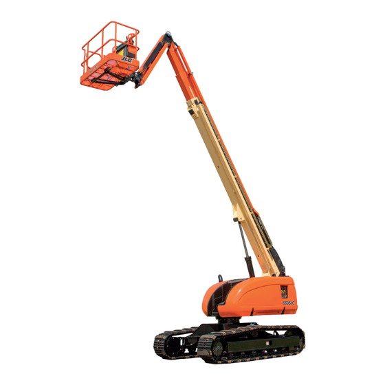
- Page 1 Operation and Safety Manual Original Instructions - Keep this manual with the machine at all times. Boom Lift Models 600SC 660SJC S/N 0300174703 to S/N 0300236298 ANSI AS/NZS 3121606 ® March 23, 2018...
- Page 2 TO PURCHASE THIS PRODUCT PLEASE CONTACT US Equipment Financing and Extended Warranties Available Discount-Equipment.com is your online resource for commercial and industrial quality parts and equipment sales. 561-964-4949 visit us on line @ www.discount-equipment.com Select an option below to find your Equipment We sell worldwide for the brands: Genie, Terex, JLG, MultiQuip, Mikasa, Essick, Whiteman, Mayco, Toro Stone, Diamond Products, Generac Magnum, Airman, Haulotte, Barreto, Power Blanket, Nifty Lift, Atlas Copco, Chicago Pneumatic, Allmand, Miller Curber, Skyjack, Lull,...
- Page 3 FOREWORD FOREWORD This manual is a very important tool! Keep it with the machine at all times. The purpose of this manual is to provide owners, users, operators, lessors, and lessees with the precautions and operating procedures essential for the safe and proper machine operation for its intended purpose. Due to continuous product improvements, JLG Industries, Inc.
- Page 4 FOREWORD SAFETY ALERT SYMBOLS AND SAFETY SIGNAL WORDS This is the Safety Alert Symbol. It is used to alert you to the potential personal injury hazards. Obey all safety messages that follow this symbol to avoid possible injury or death INDICATES A POTENTIALLY HAZARDOUS SITUATION.
- Page 5 FOREWORD For: • Accident Reporting • Standards and Regulations THIS PRODUCT MUST COMPLY WITH ALL SAFETY RELATED BULLETINS. CONTACT JLG Compliance Information INDUSTRIES, INC. OR THE LOCAL AUTHORIZED JLG REPRESENTATIVE FOR INFORMA- • Product Safety Publica- TION REGARDING SAFETY-RELATED BULLETINS WHICH MAY HAVE BEEN ISSUED FOR tions •...
- Page 6 FOREWORD REVISION LOG Original Issue - November 27, 2013 Revised - January 5, 2015 Revised - March 8, 2016 - September 20, 2017 Revised - March 23, 2018 Revised – JLG Lift – 3121606...
-
Page 7: Table Of Contents
TABLE OF CONTENTS SECTION - PARAGRAPH, SUBJECT PAGE SECTION - PARAGRAPH, SUBJECT PAGE SECTION - 1 - SAFETY PRECAUTIONS SkyGuard Function Test......2-8 General . - Page 8 TABLE OF CONTENTS SECTION - PARAGRAPH, SUBJECT PAGE SECTION - PARAGRAPH, SUBJECT PAGE Platform Rotation ....... . 4-12 SECTION - 5 - EMERGENCY PROCEDURES BOOM .
- Page 9 TABLE OF CONTENTS SECTION - PARAGRAPH, SUBJECT PAGE SECTION - PARAGRAPH, SUBJECT PAGE Preparation and Inspection ......6-8 OPERATOR MAINTENANCE .
- Page 10 LIST OF FIGURES FIGURE NUMBER - TITLE PAGE FIGURE NUMBER - TITLE PAGE 2-1. Drive Function Operating Range Diagrams - 4-10. Decal Installation - Sheet 3 of 6 ..... . 4-21 Sheet 1 of 2 .
- Page 11 LIST OF TABLES TABLE NUMBER - TITLE PAGE TABLE NUMBER - TITLE PAGE Minimum Approach Distances (M.A.D.) ....1-6 Beaufort Scale (For Reference Only)....1-9 Inspection and Maintenance Table .
-
Page 12: Section 1 - Safety Precautions
SECTION 1 - SAFETY PRECAUTIONS SECTION 1. SAFETY PRECAUTIONS GENERAL This section outlines the necessary precautions for proper and FAILURE TO COMPLY WITH THE SAFETY PRECAUTIONS LISTED IN THIS MANUAL COULD RESULT IN MACHINE DAMAGE, PROPERTY DAMAGE, PERSONAL INJURY OR safe machine usage and maintenance. -
Page 13: Workplace Inspection
SECTION 1 - SAFETY PRECAUTIONS • An operator must not accept operating responsibilities until Workplace Inspection adequate training has been given by competent and autho- • Precautions to avoid all hazards in the work area must be rized persons. taken by the user before and during operation of the machine. •... -
Page 14: Machine Inspection
SECTION 1 - SAFETY PRECAUTIONS Machine Inspection OPERATION • Do not operate this machine until the inspections and func- General tional checks as specified in Section 2 of this manual have been performed. • Machine operation requires your full attention. Bring the machine to a full stop before using any device, i.e. -
Page 15: Trip And Fall Hazards
SECTION 1 - SAFETY PRECAUTIONS • Do not carry materials directly on platform railing unless the machine will remain stationary, hydraulic oil temperature, approved by JLG. ambient air temperature, and boom and platform position. • When two or more persons are in the platform, the operator Trip and Fall Hazards shall be responsible for all machine operations. -
Page 16: Electrocution Hazards
SECTION 1 - SAFETY PRECAUTIONS • Before operating the machine, make sure all gates are closed Electrocution Hazards and fastened in their proper position. • This machine is not insulated and does not provide protection from contact or proximity to electrical current. •... - Page 17 SECTION 1 - SAFETY PRECAUTIONS Table 1-1. Minimum Approach Distances (M.A.D.) Voltage Range MINIMUM APPROACH DISTANCE (Phase to Phase) in Feet (Meters) 0 to 50 KV 10 (3) Over 50KV to 200 KV 15 (5) Over 200 KV to 350 KV 20 (6) Over 350 KV to 500 KV 25 (8)
-
Page 18: Tipping Hazards
SECTION 1 - SAFETY PRECAUTIONS • The minimum approach distance may be reduced if insulating Tipping Hazards barriers are installed to prevent contact, and the barriers are • The user must be familiar with the surface before driving. Do rated for the voltage of the line being guarded. These barriers not exceed the allowable sideslope and grade while driving. - Page 19 SECTION 1 - SAFETY PRECAUTIONS • Never exceed the maximum work load as specified on the • Do not operate the machine when wind conditions, including platform. Keep all loads within the confines of the platform, gusts, may exceed 28 mph (12.5 m/s). Factors affecting wind unless authorized by JLG.
- Page 20 SECTION 1 - SAFETY PRECAUTIONS DO NOT OPERATE THE MACHINE WHEN WIND CONDITIONS EXCEED 28 MPH (12.5 M/ Table 1-2. Beaufort Scale (For Reference Only) Wind Speed Beaufort Description Land Conditions Number 0-0.2 Calm Calm. Smoke rises vertically 0.3-1.5 Light air Wind motion visible in smoke 1.6-3.3 Light breeze...
-
Page 21: Crushing And Collision Hazards
SECTION 1 - SAFETY PRECAUTIONS Crushing and Collision Hazards • Keep non-operating personnel at least 6 ft. (1.8m) away from machine during all driving and swing operations. • Approved head gear must be worn by all operating and • Under all travel conditions, the operator must limit travel ground personnel. -
Page 22: Towing, Lifting, And Hauling
SECTION 1 - SAFETY PRECAUTIONS TOWING, LIFTING, AND HAULING MAINTENANCE • Never allow personnel in platform while towing, lifting, or This sub-section contains general safety precautions which must hauling. be observed during maintenance of this machine. Additional pre- cautions to be observed during machine maintenance are •... - Page 23 SECTION 1 - SAFETY PRECAUTIONS • DO NOT use your hand to check for leaks. Use a piece of card- • Do not use machine as a ground for welding. board or paper to search for leaks. Wear gloves to help protect •...
-
Page 24: Battery Hazards
SECTION 1 - SAFETY PRECAUTIONS Battery Hazards • Always disconnect batteries when servicing electrical compo- BATTERY FLUID IS HIGHLY CORROSIVE. AVOID CONTACT WITH SKIN AND nents or when performing welding on the machine. CLOTHING AT ALL TIMES. IMMEDIATELY RINSE ANY CONTACTED AREA WITH CLEAN WATER AND SEEK MEDICAL ATTENTION. - Page 25 TO PURCHASE THIS PRODUCT PLEASE CONTACT US Equipment Financing and Extended Warranties Available Discount-Equipment.com is your online resource for commercial and industrial quality parts and equipment sales. 561-964-4949 visit us on line @ www.discount-equipment.com Select an option below to find your Equipment We sell worldwide for the brands: Genie, Terex, JLG, MultiQuip, Mikasa, Essick, Whiteman, Mayco, Toro Stone, Diamond Products, Generac Magnum, Airman, Haulotte, Barreto, Power Blanket, Nifty Lift, Atlas Copco, Chicago Pneumatic, Allmand, Miller Curber, Skyjack, Lull,...
-
Page 26: Section 2 - User Responsibilities, Machine Preparation, And Inspection
SECTION 2 - USER RESPONSIBILITIES, MACHINE PREPARATION, AND INSPECTION SECTION 2. USER RESPONSIBILITIES, MACHINE PREPARATION, AND INSPECTION 2.1 PERSONNEL TRAINING 6. The safest means to operate the machine where overhead obstructions, other moving equipment, and obstacles, The aerial platform is a personnel handling device; so it is neces- depressions, holes, or drop-offs exist. -
Page 27: 2.2 Preparation, Inspection, And Maintenance
SECTION 2 - USER RESPONSIBILITIES, MACHINE PREPARATION, AND INSPECTION 2.2 PREPARATION, INSPECTION, AND MAINTENANCE JLG INDUSTRIES, INC. RECOGNIZES A FACTORY TRAINED SERVICE TECHNICIAN AS A The following table covers the periodic machine inspections and PERSON WHO HAS SUCCESSFULLY COMPLETED THE JLG SERVICE TRAINING SCHOOL maintenance required by JLG Industries, Inc. - Page 28 SECTION 2 - USER RESPONSIBILITIES, MACHINE PREPARATION, AND INSPECTION Table 2-1.Inspection and Maintenance Table Primary Service Type Frequency Reference Responsibility Qualification Pre-Start Inspection Before using each day; or User or Operator User or Operator Operator and Safety Manual whenever there’s an Operator change. Pre-Delivery Inspection (See Before each sale, lease, or rental delivery.
-
Page 29: Pre-Start Inspection
SECTION 2 - USER RESPONSIBILITIES, MACHINE PREPARATION, AND INSPECTION Pre-Start Inspection 5. “Walk-Around” Inspection – Refer to Figure 2-4., Figure 2- 5. and Figure 2-6. The Pre-Start Inspection shall include each of the following: 6. Battery – Charge as required. 1. -
Page 30: Daily Functional Check
SECTION 2 - USER RESPONSIBILITIES, MACHINE PREPARATION, AND INSPECTION Daily Functional Check While driving in high drive, elevate the boom to approxi- mately 10 degrees. Drive should cut back to low speed. The A functional check of all systems should be performed, once the switch should reset when the boom is fully lowered. - Page 31 SECTION 2 - USER RESPONSIBILITIES, MACHINE PREPARATION, AND INSPECTION 4. Drive Disable Switch (Refer to Figure 2-2., Drive Function face, shut down the machine, and contact a qualified techni- Operating Range Diagrams - Sheet 2 of 2). cian before resuming operation. a.
- Page 32 SECTION 2 - USER RESPONSIBILITIES, MACHINE PREPARATION, AND INSPECTION 14. Footswitch. 15. Auxiliary Power. Operate each function control switch (e.g. Tele, Lift and Swing) to assure that they function in both directions using FOOTSWITCH MUST BE ADJUSTED SO THAT FUNCTIONS WILL OPERATE WHEN PEDAL auxiliary power instead of engine power.
-
Page 33: Skyguard Function Test
SECTION 2 - USER RESPONSIBILITIES, MACHINE PREPARATION, AND INSPECTION SkyGuard Function Test NOTE: If the machine is equipped with both SkyGuard and Soft Touch, functions will not reverse, only stop. From the Platform Console: NOTE: If equipped, ensure the blue beacon illuminates when SkyGuard Test the SkyGuard feature by operating the telescope out func- is activated. - Page 34 SECTION 2 - USER RESPONSIBILITIES, MACHINE PREPARATION, AND INSPECTION 70ft. 21.34 m CHASSIS 60ft. 18.29 m LEVEL 50ft. 15.24 m NOTE: Max Drive Speed will be disabled above 40ft. 12.19 m 10° elevation or past 3 feet (1 m) of boom REDUCED extension.
- Page 35 SECTION 2 - USER RESPONSIBILITIES, MACHINE PREPARATION, AND INSPECTION 70ft. 21.34 m CHASSIS TILTED> 1.8° 60ft. 18.29 m NO DRIVE IF CHASSIS TILTED> 1.8° 50ft. 15.24 m 40ft. 12.19 m 55 DEGREES 30ft. 9.14 m 20ft. 6.10 m DRIVE PERFORMANCE MACHINE SETUP 10ft.
- Page 36 SECTION 2 - USER RESPONSIBILITIES, MACHINE PREPARATION, AND INSPECTION 70ft. 21.34 m CHASSIS 60ft. TILTED > 1.8° 18.29 m BOOM FUNCTION CREEP IF TILTED > 1.8° 50ft. 15.24 m 40ft. 12.19 m 55 DEGREES 30ft. 9.14 m BOOM FUNCTION 20ft. PERFORMANCE 6.10 m PER MACHINE...
- Page 37 SECTION 2 - USER RESPONSIBILITIES, MACHINE PREPARATION, AND INSPECTION Figure 2-4. Daily Walk-Around Inspection Diagram 2-12 – JLG Lift – 3121606...
-
Page 38: General
SECTION 2 - USER RESPONSIBILITIES, MACHINE PREPARATION, AND INSPECTION General 4. Jib (If Equipped) - See Inspection Note. Begin the "Walk-Around Inspection" at Item 1, as noted on the diagram. Continue checking each item in sequence for the con- ditions listed in the following checklist. TO AVOID POSSIBLE INJURY, BE SURE MACHINE POWER IS OFF. - Page 39 SECTION 2 - USER RESPONSIBILITIES, MACHINE PREPARATION, AND INSPECTION 11. Auxiliary Power Pump - See Inspection Note. 20. Idler - See Inspection Note. 12. Bottom Rollers - See Inspection Note. 21. Dual Capacity Limit Switch - Switch operates properly. 13. Track Carrier Roller, Both Sides - See Inspection Note. 22.
- Page 40 TO PURCHASE THIS PRODUCT PLEASE CONTACT US Equipment Financing and Extended Warranties Available Discount-Equipment.com is your online resource for commercial and industrial quality parts and equipment sales. 561-964-4949 visit us on line @ www.discount-equipment.com Select an option below to find your Equipment We sell worldwide for the brands: Genie, Terex, JLG, MultiQuip, Mikasa, Essick, Whiteman, Mayco, Toro Stone, Diamond Products, Generac Magnum, Airman, Haulotte, Barreto, Power Blanket, Nifty Lift, Atlas Copco, Chicago Pneumatic, Allmand, Miller Curber, Skyjack, Lull,...
-
Page 41: Section 3 - Machine Controls And Indicators
SECTION 3 - MACHINE CONTROLS AND INDICATORS SECTION 3. MACHINE CONTROLS AND INDICATORS GENERAL NOTE: The indicator panels use different shaped symbols to alert the operator to different types of operational situations that could arise. The meaning of those symbols are explained below. Indicates a potentially hazardous situation, which if THE MANUFACTURER HAS NO DIRECT CONTROL OVER MACHINE APPLICATION AND not corrected, could result in serious injury or death. -
Page 42: Ground Control Station
SECTION 3 - MACHINE CONTROLS AND INDICATORS Ground Control Station (See Figure 3-1., Figure 3-2., Figure 3-3., and Figure 3-4.) ONLY USE THE PLATFORM LEVELING OVERRIDE FUNCTION FOR SLIGHT LEVELING OF THE PLATFORM. INCORRECT USE COULD CAUSE THE LOAD/OCCUPANT TO SHIFT OR NOTE: The Function Enable switch must be held down in FALL. - Page 43 SECTION 3 - MACHINE CONTROLS AND INDICATORS 1. Platform Rotate 2. Platform Leveling Override 3. Not Used 4. Power/Emergency Stop 5. Engine Start/Auxiliary Power/Function Enable 6. Lift 7. Hourmeter 8. Platform/Ground Select Switch 9. Swing 10. Telescope 11. Indicator Panel 12.
- Page 44 SECTION 3 - MACHINE CONTROLS AND INDICATORS 1. Platform Rotate 2. Platform Leveling Override 3. Not Used 4. Power/Emergency Stop 5. Engine Start/Auxiliary Power/Function Enable 6. Lift 7. Hourmeter 8. Platform/Ground Select Switch 9. Swing 10. Telescope 11. Indicator Panel 12.
- Page 45 SECTION 3 - MACHINE CONTROLS AND INDICATORS 1. Platform Rotate 2. Platform Leveling Override 3. Jib 4. Power/Emergency Stop 5. Engine Start/Auxiliary Power/Function Enable 6. Lift 7. Hourmeter 8. Platform/Ground Select Switch 9. Swing 10. Telescope 11. Indicator Panel 12. Not Used 13.
- Page 46 SECTION 3 - MACHINE CONTROLS AND INDICATORS 1. Platform Rotate 2. Platform Leveling Override 3. Jib 4. Power/Emergency Stop 5. Engine Start/Auxiliary Power/Function Enable 6. Lift 7. Hourmeter 8. Platform/Ground Select Switch 9. Swing 10. Telescope 11. Indicator Panel 12. Machine Safety System Override (MSSO) Figure 3-4.
- Page 47 SECTION 3 - MACHINE CONTROLS AND INDICATORS NOTE: When Power/Emergency Stop switch is in the “ON” position and 5. Engine Start/ Auxiliary Power Switch /Function Enable engine is not running, an alarm will sound, indicating Ignition is To start the engine, the switch must be held “ON”.
- Page 48 SECTION 3 - MACHINE CONTROLS AND INDICATORS NOTE: When the Platform/Ground Select Switch is in the center position, power is shut off to the controls at both operating stations. Remove the key to pre- WHEN OPERATING THE BOOM ENSURE THERE ARE NO PERSONNEL AROUND OR vent the controls from being actuated.
-
Page 49: Ground Control Indictor Panel
SECTION 3 - MACHINE CONTROLS AND INDICATORS 11. Indicator Panel 2. Engine Oil Pressure Indicator The LED Indicator Panel contains indicator lights that signal Indicates that engine oil pressure is below nor- problem conditions or functions operating during machine mal and service is required. operation. - Page 50 SECTION 3 - MACHINE CONTROLS AND INDICATORS 1. Battery Charging 5. Low Fuel 2. Engine Oil Pressure 6. Glow Plug 3. Engine Oil Temp. 7. Platform Overload 4. Malfunction Indicator Figure 3-5. Ground Control Indicator Panel 3-10 – JLG Lift – 3121606...
-
Page 51: Platform Control Station
SECTION 3 - MACHINE CONTROLS AND INDICATORS 6. Glow Plug/ Wait to Start Indicator Platform Control Station (See Figure 3-6., Platform Control Console) Indicates the glow plugs are on. The glow plugs are automatically turned on with the ignition circuit and remain on for approxi- mately seven seconds. - Page 52 SECTION 3 - MACHINE CONTROLS AND INDICATORS 1. Drive Speed / Torque Select 5. Start / Aux Power 9. Telescope 13. Soft Touch/SkyGuard Indicator 2. Platform Level Override 6. Drive Orientation Override 10. Lights 14. Platform Rotate 3. Horn 7. Drive/Steer Enable 11.
- Page 53 SECTION 3 - MACHINE CONTROLS AND INDICATORS 4. Power/Emergency Stop Switch A two-position red mushroom shaped switch ONLY USE THE PLATFORM LEVELING OVERRIDE FUNCTION FOR SLIGHT LEVELING OF furnishes power to Platform Controls when THE PLATFORM. INCORRECT USE COULD CAUSE THE LOAD/OCCUPANT TO SHIFT OR pulled out (on).
- Page 54 SECTION 3 - MACHINE CONTROLS AND INDICATORS 6. Drive Orientation Override 8. Drive/Steer When the boom is swung over the rear in Proportional dual axis joystick is provided either direction, the Drive Orientation indica- to control drive and steer. Push forward to tor will illuminate when the drive function is drive straight forward.
- Page 55 SECTION 3 - MACHINE CONTROLS AND INDICATORS NOTE: When boom is positioned above horizontal and any of the fol- 11. Jib (If Equipped) lowing switches, DRIVE SPEED/TORQUE SELECT or FUNCTION SPEED, are positioned to HIGH, high function speeds are auto- Push forward to lift up, pull back to lift down.
- Page 56 SECTION 3 - MACHINE CONTROLS AND INDICATORS If equipped with both Soft Touch and NOTE: To operate the Main Boom Lift/Swing joystick, SkyGuard, the switch operates like pull up on the locking ring below the handle. described above and allows the opera- tor to override the system that has NOTE: The Main Boom Lift/Swing joystick is spring...
-
Page 57: Platform Control Indicator Panel
SECTION 3 - MACHINE CONTROLS AND INDICATORS Platform Control Indicator Panel 3. Capacity Indicator (See Figure 3-7., Platform Control Indicator Panel) Indicates the maximum platform capacity for the current position of the platform. 1. Tilt Alarm Warning Light and Alarm Restricted capacities permitted... - Page 58 SECTION 3 - MACHINE CONTROLS AND INDICATORS Tilt Alarm Warning 5. Footswitch/Enable 9. AC Generator 2. Platform Overload 6. Glow Plug 10. Not Used 3. Platform Capacity 7. Low Fuel 11. Creep Speed 4. Drive Disabled 8. System Distress 12. Drive Orientation Figure 3-7.
- Page 59 SECTION 3 - MACHINE CONTROLS AND INDICATORS 5. Footswitch/Enable Indicator 6. Glow Plug/Wait to Start Indicator To operate any function, the footswitch must Indicates the glow plugs are operating. After be depressed and the function selected within turning on ignition, wait until light goes out seven seconds.
- Page 60 SECTION 3 - MACHINE CONTROLS AND INDICATORS 10. Drive Orientation Indicator 11. Creep Speed Indicator When the boom is swung beyond the rear in When the Function Speed Control is turned to either direction, the Drive Orientation indica- the creep position, the indicator acts as a tor will illuminate when the drive function is reminder that all functions are set to the slow- selected.
- Page 61 TO PURCHASE THIS PRODUCT PLEASE CONTACT US Equipment Financing and Extended Warranties Available Discount-Equipment.com is your online resource for commercial and industrial quality parts and equipment sales. 561-964-4949 visit us on line @ www.discount-equipment.com Select an option below to find your Equipment We sell worldwide for the brands: Genie, Terex, JLG, MultiQuip, Mikasa, Essick, Whiteman, Mayco, Toro Stone, Diamond Products, Generac Magnum, Airman, Haulotte, Barreto, Power Blanket, Nifty Lift, Atlas Copco, Chicago Pneumatic, Allmand, Miller Curber, Skyjack, Lull,...
-
Page 62: Section 4 - Machine Operation
SECTION 4 - MACHINE OPERATION SECTION 4. MACHINE OPERATION DESCRIPTION OPERATING CHARACTERISTICS AND LIMITATIONS This machine is a self-propelled hydraulic lift equipped with a Capacities work platform on the end of an elevating and rotating boom. The boom can be raised above horizontal with or without any The primary operator control station is in the platform. -
Page 63: Stability
SECTION 4 - MACHINE OPERATION Stability Machine stability is based on two positions which are called FOR- WARD STABILITY and BACKWARD STABILITY. The machines posi- tion of Least Backward Stability is shown in Figure 4-1., and its position of Least Forward Stability is shown in Figure 4-2. MACHINE WILL UPSET PLATFORM ROTATED IN THIS DIRECTION IF... - Page 64 SECTION 4 - MACHINE OPERATION BOOM FULLY EXTENDED @ HORIZONTAL (O DEGREES) MACHINE WILL UPSET IN THIS DIRECTION IF OVERLOADED OR OPERATED ON AN OUT-OF-LEVEL SURFACE LEVEL SURFACE Figure 4-2. Position of Least Forward Stability 3121606 – JLG Lift –...
-
Page 65: Engine Operation
SECTION 4 - MACHINE OPERATION ENGINE OPERATION 2. Pull the Power/Emergency Stop switch to On. NOTE: Initial starting should always be performed from the Ground Control station. 3. Push the Engine Start switch until engine starts. Starting Procedure ALLOW ENGINE TO WARM-UP FOR A FEW MINUTES AT LOW SPEED BEFORE APPLYING ANY LOAD. -
Page 66: Shutdown Procedure
SECTION 4 - MACHINE OPERATION 7. Push the Engine Start switch until engine starts. Air Shutoff Valve (ASOV) (If Equipped) Air Shutoff Valve (ASOV ) is an overspeed protection device mounted to the engine’s air intake system. When the valve is NOTE: Footswitch must be in released (up) position before starter will actuated, it obstructs airflow intake and stops the engine. -
Page 67: Traveling (Driving)
SECTION 4 - MACHINE OPERATION TRAVELING (DRIVING) DO NOT USE ASOV AS AN ALTERNATIVE TO SHUTTING DOWN MACHINE PROPERLY. See Figure 4-4., Grades and Sideslopes. NOTE: Refer to the Operating Specifications table for Gradeability and Sideslope ratings. All ratings for Gradeability and Sideslope are based upon the machine’s boom being in the stowed position, fully lowered, and retracted. - Page 68 SECTION 4 - MACHINE OPERATION Figure 4-4. Grades and Sideslopes 3121606 – JLG Lift –...
- Page 69 SECTION 4 - MACHINE OPERATION Figure 4-5. Machine Motion Hazard – JLG Lift – 3121606...
-
Page 70: Traveling Forward Or Reverse
SECTION 4 - MACHINE OPERATION DO NOT DRIVE WITH BOOM EXTENDED OR ABOVE HORIZONTAL EXCEPT ON A USE EXTREME CAUTION WHEN APPROACHING A CREST OF ANY TERRAIN OBSTACLE. SMOOTH, FIRM AND LEVEL SURFACE. CHECK FOR CURBS, LARGE STONES, OR OTHER TERRAIN OBSTACLES INCLUDING OVERHEAD OBSTACLES AS THE MACHINE WILL MAKE UNCONTROLLED PIVOTING TO AVOID LOSS OF TRAVEL CONTROL OR UPSET ON GRADES AND SIDESLOPES, DO NOT MOTIONS WHEN THE CENTER OF GRAVITY (CENTER OF TRACK FRAME) SHIFTS OVER... - Page 71 SECTION 4 - MACHINE OPERATION 3. Depress footswitch, move joystick (Drive/ 6. To obtain maximum travel speed, position the Drive control- Steer Control) to select desired direction of ler to Fast and activate the following switches: travel (forward or reverse), move Drive/ a.
-
Page 72: Traveling On A Grade
SECTION 4 - MACHINE OPERATION This machine is equipped with a Drive Orientation Traveling on a Grade Indicator. The yellow light on the platform control console indicates that the boom is swung beyond When traveling a grade, maximum braking and traction are obtained the rear and the machine may Drive/Steer in the with the boom stowed, in position over the rear drive, and in line opposite direction from the movement of the con-... -
Page 73: Parking And Stowing
SECTION 4 - MACHINE OPERATION PARKING AND STOWING PLATFORM Park and stow machine as follows: Platform Level Adjustment 1. Park machine in travel position; boom lowered over rear, all access panels and doors closed and secured, ignition off, turntable locked. ONLY USE THE PLATFORM LEVELING OVERRIDE FUNCTION FOR SLIGHT LEVELING OF 2. -
Page 74: Boom
SECTION 4 - MACHINE OPERATION BOOM SWITCH OR LEVER IS RELEASED, REMOVE FOOT FROM FOOTSWITCH OR USE EMER- GENCY STOP TO STOP THE MACHINE. Swinging the Boom A RED TILT ALARM WARNING LIGHT, LOCATED ON THE CONTROL CON- SOLE, LIGHTS WHEN THE CHASSIS IS ON A SEVERE SLOPE (5 DEGREES To swing boom, use Swing control switch to select OR GREATER). -
Page 75: Telescoping The Main Boom
SECTION 4 - MACHINE OPERATION Telescoping the Main Boom MACHINE SAFETY SYSTEM OVERRIDE (MSSO)(CE ONLY) To extend or retract the main boom, use the Main The Machine Safety System Override (MSSO) is Telescope Control Switch to select In or Out move- used to override function controls for Emergency ment. -
Page 76: 4.10 Skyguard Operation
SECTION 4 - MACHINE OPERATION 4.10 SKYGUARD OPERATION Skyguard is used to provide enhanced control panel protection. When the SkyGuard sensor is activated, functions that were in use at the time of actuation will reverse or cutout. The table below outlines these functions. Table 4-1. -
Page 77: 4.11 Tie Down And Lifting
SECTION 4 - MACHINE OPERATION 4.11 TIE DOWN AND LIFTING 4. Attach lifting device and equipment only to the designated lifting points. Tie Down 5. Properly adjust the rigging to prevent damage to the machine and so the machine remains level. 4.12 AUXILIARY POWER WHEN TRANSPORTING THE MACHINE, THE BOOM MUST BE FULLY LOWERED INTO THE BOOM REST. - Page 78 SECTION 4 - MACHINE OPERATION Figure 4-7. Lifting Chart 3121606 – JLG Lift – 4-17...
-
Page 79: Activating From The Ground Control Station
SECTION 4 - MACHINE OPERATION 4. Position Auxiliary Power switch to On and hold. Activating from the Ground Control Station 1. Position Platform/Ground Select Key Switch to Ground. 5. Operate appropriate control switch, lever or control- ler for desired function and hold. 6. - Page 80 SECTION 4 - MACHINE OPERATION D AN G E R W A R N IN G C R US H IN G H A Z A R D E LE C TR O C U TIO N H A Z A R D D o n o t s ta n d u n d er a r a i s e d p la t f or m o r b oo m , o r b e tw e e n a ro ta ti n g p la t f o rm a n d t h e b oo m .
- Page 81 SECTION 4 - MACHINE OPERATION C E /A U S 1705961 1701518 D A N G E R E LE C TR O C U T I O N H A Z A R D T his ma c hi n e is not insulated. M aint a in a c l e ara nce of at l e ast 10 ft.
- Page 82 SECTION 4 - MACHINE OPERATION E -E V IE W D -D V IE W G R A D A LL U N D E R C A R R IA G E Figure 4-10. Decal Installation - Sheet 3 of 6 3121606 –...
- Page 83 SECTION 4 - MACHINE OPERATION C A LLE D O U T O N M A C H IN E LIF T IN G A TT A C H IN S L'L 120V - 6 0H Z 3 2 5 12 4 3 A N S I D AN G E R E L E C TR O C U TIO N HA Z A RD...
- Page 84 SECTION 4 - MACHINE OPERATION Figure 4-12. Decal Installation - Sheet 5 of 6 3121606 – JLG Lift – 4-23...
- Page 85 SECTION 4 - MACHINE OPERATION Figure 4-13. Decal Installation - Sheet 6 of 6 4-24 – JLG Lift – 3121606...
- Page 86 SECTION 4 - MACHINE OPERATION Table 4-2. 600SC Decal Legend Canadian English/ Simplified Traditional Item # ANSI CE/Australian French Portuguese Chinese Chinese 0273906-D 0273985-E 0273982-D 1001093424-D 1001116970-D 1001116971-D 1701499 1701499 1701499 1701499 1701499 1701499 1701502 1701502 1701502 1701502 1701502 1701502 1701503 1701503 1701503...
- Page 87 SECTION 4 - MACHINE OPERATION Table 4-2. 600SC Decal Legend Canadian English/ Simplified Traditional Item # ANSI CE/Australian French Portuguese Chinese Chinese 0273906-D 0273985-E 0273982-D 1001093424-D 1001116970-D 1001116971-D 1705904 1705342 1001117034 1705906 1705507 1001117035 1703953 1703942 1705903 1001116845 1703943 1702868 1704000 1705967 1705968...
- Page 88 SECTION 4 - MACHINE OPERATION Table 4-2. 600SC Decal Legend Canadian English/ Simplified Traditional Item # ANSI CE/Australian French Portuguese Chinese Chinese 0273906-D 0273985-E 0273982-D 1001093424-D 1001116970-D 1001116971-D 1001121813 1001121815 1705978 1001121819 1001121824 1001121822 1704885 1704885 1704885 1704885 1704885 1704885 1706948 1706948 1706948...
- Page 89 SECTION 4 - MACHINE OPERATION Table 4-2. 600SC Decal Legend Canadian English/ Simplified Traditional Item # ANSI CE/Australian French Portuguese Chinese Chinese 0273906-D 0273985-E 0273982-D 1001093424-D 1001116970-D 1001116971-D 1704468 1001093684 1704468 1001093439 1001116963 1001116964 1001108494 1001108494 1001108494 1001108494 1001108494 1706943 1706943 1706943 1706943...
- Page 90 SECTION 4 - MACHINE OPERATION Table 4-3. 660SJC Decal Legend Table 4-3. 660SJC Decal Legend Canadian English/ Canadian English/ Item # ANSI CE/Australian Item # ANSI CE/Australian French Portuguese French Portuguese 0273908-D 0273987-E 0273908-D 0273987-E 0273984-D 1001103292-D 0273984-D 1001103292-D 1705904 1701499 1701499 1701499...
- Page 91 SECTION 4 - MACHINE OPERATION Table 4-3. 660SJC Decal Legend Table 4-3. 660SJC Decal Legend Canadian English/ Canadian English/ Item # ANSI CE/Australian Item # ANSI CE/Australian French Portuguese French Portuguese 0273908-D 0273987-E 0273908-D 0273987-E 0273984-D 1001103292-D 0273984-D 1001103292-D 1001121814 1001121816 1705978 1001121655...
- Page 92 TO PURCHASE THIS PRODUCT PLEASE CONTACT US Equipment Financing and Extended Warranties Available Discount-Equipment.com is your online resource for commercial and industrial quality parts and equipment sales. 561-964-4949 visit us on line @ www.discount-equipment.com Select an option below to find your Equipment We sell worldwide for the brands: Genie, Terex, JLG, MultiQuip, Mikasa, Essick, Whiteman, Mayco, Toro Stone, Diamond Products, Generac Magnum, Airman, Haulotte, Barreto, Power Blanket, Nifty Lift, Atlas Copco, Chicago Pneumatic, Allmand, Miller Curber, Skyjack, Lull,...
-
Page 93: Section 5 - Emergency Procedures
SECTION 5 - EMERGENCY PROCEDURES SECTION 5. EMERGENCY PROCEDURES GENERAL Failure to notify the manufacturer of an incident involving a JLG Industries product within 48 hours of such an occurrence may This section explains the steps to be taken in case of an emer- void any warranty consideration on that particular machine. -
Page 94: Emergency Operation
SECTION 5 - EMERGENCY PROCEDURES EMERGENCY OPERATION MACHINE SAFETY SYSTEM OVERRIDE (MSSO)(CE ONLY) Operator Unable to Control Machine The Machine Safety System Override (MSSO) is IF THE PLATFORM OPERATOR IS PINNED, TRAPPED OR UNABLE TO only to be used to retrieve an operator that is OPERATE OR CONTROL MACHINE: pinned, trapped, or unable to operate the machine and function controls are locked out... -
Page 95: Section 6 - Accessories
SECTION 6 - ACCESSORIES SECTION 6. ACCESSORIES Table 6-1. Available Accessories Market Accessory ANSI ANSI Japan China (USA Only) √ √ √ √ SkyAir™ √ √ √ √ SkyCutter™ √ √ √ SkyGlazier™ SkyPower™ √ √ √ √ √ √ √... - Page 96 SECTION 6 - ACCESSORIES Table 6-2. Options/Accessories Relationship Table COMPATIBLE WITH ACCESSORY REQUIRED ITEM INCOMPATIBLE WITH INTERCHANGABLE WITH (Note 2) (Note 1) SkyCutter™, SkyGlazier™, SkyAir™ SkyPower™ SkyWelder™ SkyCutter™ SkyPower™ SkyWelder™ Platform MTR* SkyGlazier™ SkyGlazier™ SkyPower™ Platform MTR* SkyCutter™, SkyWelder™ SkyCutter™, SkyGlazier™, SkyPower™...
-
Page 97: Skyair
SECTION 6 - ACCESSORIES SKYAIR™ Compressor Specifications • Single stage with dual control • CFM displacement: 9.3 • Motor: 230 V, 2 hp, 3-phase Accessory Ratings CONTROL MODE VOLUME Automatic Start-Stop Control 100 - 130 psi Constant Run Control 105 - 120 psi Safety Precautions DO NOT OVERLOAD PLATFORM. -
Page 98: Preparation And Inspection
SECTION 6 - ACCESSORIES Preparation and Inspection SKYCUTTER™ • Ensure compressor and hoses are secure. • Check condition of belt and wiring. Operation Start the engine, turn on the generator, then turn on the air com- pressor. Refer to the J-Air Manual (PN 3128970) for more information. SkyCutter™... -
Page 99: Accessory Ratings
SECTION 6 - ACCESSORIES Accessory Ratings Amperes Input @ Plasma Gas Flow/ Rated Cutting Spec. Rated Output Rated Output, 60 kVa/kW Plasma Gas Max. OCV Pressure Capacity @ 10 IPM Hz, 1-Phase 120 Volts ±10% 27 A @ 91 VDC @ 20% 28.8 max;... -
Page 100: Preparation And Inspection
SECTION 6 - ACCESSORIES • Ensure no personnel are beneath platform. SKYGLAZIER™ • Do not exit platform over rails or stand on rails. • Use this option only on approved models. • Keep lanyard attached at all times. • Use correct cutting settings. •... -
Page 101: Capacity Specifications
SECTION 6 - ACCESSORIES Capacity Specifications Safety Precautions Max. Platform Capacity Capacity Zone * Max. Tray Capacity (With Max. Weight in Tray) ENSURE PANEL IS SECURED WITH STRAP. 500 lbs 150 lbs 250 lbs (227 kg) (68 kg) (113 kg) 550 lbs 150 lbs 250 lbs... -
Page 102: Preparation And Inspection
SECTION 6 - ACCESSORIES Preparation and Inspection SKYPOWER™ • Check for cracked welds and damage to tray. • Ensure tray is properly secured to platform. • Ensure strap is not torn or frayed. Operation 1. Load SkyGlazier™ tray with panel. 2. -
Page 103: Generator Output
SECTION 6 - ACCESSORIES All power regulation components are located in a watertight box Safety Precautions connected by cable to the generator. The generator supplies power when running at the specified speed with the power switch on (switch is located on platform). A three-pole, 30 Amp DO NOT OVERLOAD PLATFORM. -
Page 104: Skywelder
SECTION 6 - ACCESSORIES SKYWELDER™ Generator Output Engine Speed of 1800 rpm +/- 10%. ANSI Specifications: • 3-phase: 240 V, 60 Hz, 7.5 kW • 1-phase: 240 V/120 V, 60 Hz, 6 kW CE Specifications: • 3-phase: 400 V, 50 Hz, 7.5 kW •... -
Page 105: Accessory Ratings
SECTION 6 - ACCESSORIES Accessory Ratings Welding Amps Input At Rated Load Output (50/60 Hz) Maximum Open Welding Mode Input Power Rated Output Amperage Circuit Voltage 230 V 460 V 575 V Range 280 Amp at 31.2 V, 15.7 35% Duty Cycle 3- phase 5-250 A 79 VDC... -
Page 106: Safety Precautions
SECTION 6 - ACCESSORIES Safety Precautions • Do not ground through the platform. • Do not use a high frequency arc starter with TIG welder. Preparation and Inspection DO NOT OVERLOAD PLATFORM. • Connect ground clamp to metal being welded. •... - Page 107 TO PURCHASE THIS PRODUCT PLEASE CONTACT US Equipment Financing and Extended Warranties Available Discount-Equipment.com is your online resource for commercial and industrial quality parts and equipment sales. 561-964-4949 visit us on line @ www.discount-equipment.com Select an option below to find your Equipment We sell worldwide for the brands: Genie, Terex, JLG, MultiQuip, Mikasa, Essick, Whiteman, Mayco, Toro Stone, Diamond Products, Generac Magnum, Airman, Haulotte, Barreto, Power Blanket, Nifty Lift, Atlas Copco, Chicago Pneumatic, Allmand, Miller Curber, Skyjack, Lull,...
-
Page 108: Section 7 - General Specifications & Operator Maintenance
SECTION 7 - GENERAL SPECIFICATIONS & OPERATOR MAINTENANCE SECTION 7. GENERAL SPECIFICATIONS & OPERATOR MAINTENANCE INTRODUCTION OPERATING SPECIFICATIONS This section of the manual provides additional necessary infor- Table 7-1. Operating Specifications mation to the operator for proper operation and maintenance of this machine. -
Page 109: Capacities
SECTION 7 - GENERAL SPECIFICATIONS & OPERATOR MAINTENANCE Table 7-1. Operating Specifications Capacities Maximum Ground Bearing Pressure Table 7-2. Capacities 600SC 5.45 psi (0.383 kg/cm Fuel Tank 39 US. Gallons (147.6 L) 660SJC 6.5 psi (0.457 kg/cm Hydraulic Oil Tank Maximum Drive Speed: 1.6 mph (2.6 kph) Total Volume... -
Page 110: Engine Data
SECTION 7 - GENERAL SPECIFICATIONS & OPERATOR MAINTENANCE Engine Data Hydraulic Oil Table 7-3. Deutz D2011L04 Specifications Table 7-4. Hydraulic Oil Fuel Diesel HYDRAULIC SYSTEM OPERATING SAE VISCOSITY GRADE TEMPERATURE RANGE Oil Capacity Cooling System 5 Quarts (4.5 L) +0° to +180° F (-18° C to +83° C) Crankcase 11 Quarts (10.5 L) w/Filter +0°... - Page 111 SECTION 7 - GENERAL SPECIFICATIONS & OPERATOR MAINTENANCE Table 7-5. Mobilfluid 424 Specs Table 7-6. Mobil DTE 10 Excel 32 Specs SAE Grade 10W30 ISO Viscosity Grade Gravity, API 29.0 Specific Gravity 0.877 Density, Lb/Gal. 60°F 7.35 Pour Point, Max -65.2°F (-54°C) Pour Point, Max -46°F (-43°C)
- Page 112 SECTION 7 - GENERAL SPECIFICATIONS & OPERATOR MAINTENANCE Table 7-7. Quintolubric 888-46 Table 7-8. Mobil EAL 224H Specs Density @ 15° Type Synthetic Biodegradable ISO Viscosity Grade 32/46 Pour Point 275°C (527°F) Specific Gravity .922 Flash Point 325°C (617°F) Pour Point, Max -25°F (-32°C) Fire Point 50-0 ml...
- Page 113 SECTION 7 - GENERAL SPECIFICATIONS & OPERATOR MAINTENANCE Table 7-9. Mobil EAL H 46 Specs Table 7-10. Exxon Univis HVI 26 Specs Type Synthetic Biodegradable Specific Gravity 32.1 ISO Viscosity Grade Pour Point -76°F (-60°C) Specific Gravity .910 Flash Point 217°F (103°C) Pour Point -44°F (-42°C)
-
Page 114: Major Component Weights
SECTION 7 - GENERAL SPECIFICATIONS & OPERATOR MAINTENANCE Major Component Weights Serial Number Locations A serial number plate is affixed to the left rear side of the frame. If Table 7-11. Major Component Weights the serial number plate is damaged or missing, the machine serial number is stamped on the left side of the frame. - Page 115 SECTION 7 - GENERAL SPECIFICATIONS & OPERATOR MAINTENANCE SERIAL NUMBER SERIAL NUMBER (STAMPED ON FRAME) PLATE Figure 7-1. Serial Number Locations – JLG Lift – 3121606...
- Page 116 SECTION 7 - GENERAL SPECIFICATIONS & OPERATOR MAINTENANCE Figure 7-2. Engine Operating Temperature Specifications - Deutz - Sheet 1 of 2 3121606 – JLG Lift –...
- Page 117 SECTION 7 - GENERAL SPECIFICATIONS & OPERATOR MAINTENANCE 4150548-E Figure 7-3. Engine Operating Temperature Specifications - Deutz - Sheet 2 of 2 7-10 – JLG Lift – 3121606...
- Page 118 SECTION 7 - GENERAL SPECIFICATIONS & OPERATOR MAINTENANCE Figure 7-4. Operator Maintenance and Lubrication Diagram 3121606 – JLG Lift – 7-11...
- Page 119 SECTION 7 - GENERAL SPECIFICATIONS & OPERATOR MAINTENANCE OPERATOR MAINTENANCE 1. Swing Bearing NOTE: The following numbers correspond to those in Figure 7-4., Oper- ator Maintenance and Lubrication Diagram. Table 7-12. Lubrication Specifications SPECIFICATIONS Multipurpose Grease having a minimum dripping point of 350° F (177° C). Excel- lent water resistance and adhesive qualities, and being of extreme pressure type.
- Page 120 SECTION 7 - GENERAL SPECIFICATIONS & OPERATOR MAINTENANCE 2. Swing Drive Hub 4. Hydraulic Return Filter Lube Point(s) - Level/Fill Plug Interval - Change after first 50 hrs. and every 6 months or 300 Capacity - 17 oz. (1/2 Full) hrs.
- Page 121 SECTION 7 - GENERAL SPECIFICATIONS & OPERATOR MAINTENANCE 5. Hydraulic Charge Filter 6. Hydraulic Tank NORMAL OPERATING RANGE WITH BOOM IN STOWED POSITION Lube Point(s) - Fill Cap Capacity - 30.6 gal. Tank; 32.7 gal. System Interval - Change after first 50 hrs. and every 6 months or 300 Lube - HO hrs.
- Page 122 SECTION 7 - GENERAL SPECIFICATIONS & OPERATOR MAINTENANCE 7. Oil Change w/Filter - Deutz 8. Fuel Filter - Deutz Lube Point(s) - Fill Cap/Spin-on Element Lube Point(s) - Replaceable Element Capacity - 11 Quarts Crankcase; 5 Quarts Cooler Interval - Every Year or 600 hours of operation Lube - EO Interval - Every Year or 1200 hours of operation Comments - Check level daily/Change in accordance with...
- Page 123 SECTION 7 - GENERAL SPECIFICATIONS & OPERATOR MAINTENANCE 9. Air Filter SUPPLEMENTAL INFORMATION The following information is provided in accordance with the requirements of the European Machinery Directive 2006/42/EC and is only applicable to CE machines. For electric powered machines, the equivalent continuous A- Weighted sound pressure level at the work platform is less than 70dB(A) For combustion engine powered machines, guaranteed Sound...
- Page 125 Corporate Office JLG Industries, Inc. 1 JLG Drive McConnellsburg, PA 17233-9533 USA (717) 485-5161 (Corporate) (877) 554-5438 (Customer Support) (717) 485-6417 Visit our website for JLG Worldwide Locations. www.jlg.com...
- Page 126 TO PURCHASE THIS PRODUCT PLEASE CONTACT US Equipment Financing and Extended Warranties Available Discount-Equipment.com is your online resource for commercial and industrial quality parts and equipment sales. 561-964-4949 visit us on line @ www.discount-equipment.com Select an option below to find your Equipment We sell worldwide for the brands: Genie, Terex, JLG, MultiQuip, Mikasa, Essick, Whiteman, Mayco, Toro Stone, Diamond Products, Generac Magnum, Airman, Haulotte, Barreto, Power Blanket, Nifty Lift, Atlas Copco, Chicago Pneumatic, Allmand, Miller Curber, Skyjack, Lull,...
Need help?
Do you have a question about the JLG 600SC and is the answer not in the manual?
Questions and answers