Oshkosh Corporation JLG E300AJ Operation And Safety Manual
Hide thumbs
Also See for JLG E300AJ:
- Service and maintenance manual (437 pages) ,
- Operation and safety manual (92 pages) ,
- Original instructions manual (100 pages)

Related Manuals for Oshkosh Corporation JLG E300AJ


Summary of Contents for Oshkosh Corporation JLG E300AJ
- Page 1 Operation and Safety Manual Original Instructions - Keep this manual with the machine at all times. Boom Lift Models E300AJ E300AJP S/N 0300211844 to Present AS/NZS ANSI 3121719 ® November 5, 2018 - Rev E...
- Page 2 TO PURCHASE THIS PRODUCT PLEASE CONTACT US Equipment Financing and Extended Warranties Available Discount-Equipment.com is your online resource for commercial and industrial quality parts and equipment sales. 561-964-4949 visit us on line @ www.discount-equipment.com Select an option below to find your Equipment We sell worldwide for the brands: Genie, Terex, JLG, MultiQuip, Mikasa, Essick, Whiteman, Mayco, Toro Stone, Diamond Products, Generac Magnum, Airman, Haulotte, Barreto, Power Blanket, Nifty Lift, Atlas Copco, Chicago Pneumatic, Allmand, Miller Curber, Skyjack, Lull,...
- Page 3 WARNING Operating, servicing and maintaining this vehicle or equipment can expose you to chemicals including engine exhaust, carbon monoxide, phthalates, and lead, which are known to the State of California to cause cancer and birth defects or other reproductive harm. To minimize exposure, avoid breathing exhaust, do not idle the engine except as necessary, service your vehicle or equipment in a well-ventilated area and wear gloves or wash your hands frequently when servicing.
- Page 4 FOREWORD FOREWORD This manual is a very important tool! Keep it with the machine at all times. The purpose of this manual is to provide owners, users, operators, lessors, and lessees with the precautions and operating procedures essential for the safe and proper machine operation for its intended purpose. Due to continuous product improvements, JLG Industries, Inc.
- Page 5 FOREWORD SAFETY ALERT SYMBOLS AND SAFETY SIGNAL WORDS This is the Safety Alert Symbol. It is used to alert you to the potential personal injury hazards. Obey all safety messages that follow this symbol to avoid possible injury or death INDICATES A POTENTIALLY HAZARDOUS SITUATION.
- Page 6 FOREWORD For: • Accident Reporting • Standards and Regulations THIS PRODUCT MUST COMPLY WITH ALL SAFETY RELATED BULLETINS. CONTACT JLG Compliance Information INDUSTRIES, INC. OR THE LOCAL AUTHORIZED JLG REPRESENTATIVE FOR INFORMA- • Product Safety Publica- TION REGARDING SAFETY-RELATED BULLETINS WHICH MAY HAVE BEEN ISSUED FOR tions •...
- Page 7 FOREWORD REVISION LOG Original Issue A - September 30, 2015 Revised B - October 19, 2015 Revised C - May 30, 2018 Revised D - June 29, 2018 - Revised Covers, Prop 65 Revised E - November 5, 2018 3121719...
-
Page 8: Table Of Contents
TABLE OF CONTENTS SECTION - PARAGRAPH, SUBJECT PAGE SECTION - PARAGRAPH, SUBJECT PAGE SECTION - 1 - SAFETY PRECAUTIONS Function Check........2-8 SkyGuard Function Test. - Page 9 TABLE OF CONTENTS SECTION - PARAGRAPH, SUBJECT PAGE SECTION - PARAGRAPH, SUBJECT PAGE Platform Rotation ....... . . 4-9 EMERGENCY TOWING PROCEDURES.
- Page 10 TABLE OF CONTENTS SECTION - PARAGRAPH, SUBJECT PAGE SECTION - PARAGRAPH, SUBJECT PAGE OPERATOR MAINTENANCE ......7-10 BATTERY MAINTENANCE AND CHARGING.
- Page 11 TABLE OF CONTENTS SECTION - PARAGRAPH, SUBJECT PAGE SECTION - PARAGRAPH, SUBJECT PAGE This Page Left Blank Intentionally 3121719...
- Page 12 LIST OF FIGURES FIGURE NUMBER - TITLE PAGE FIGURE NUMBER - TITLE PAGE 2-1. Basic Nomenclature........2-4 4-18.
- Page 13 LIST OF FIGURES FIGURE NUMBER - TITLE PAGE FIGURE NUMBER - TITLE PAGE 4-44. Portuguese Decal Location Sheet 3 of 5 ... . . 4-66 4-45. Portuguese Decal Location Sheet 4 of 5 ... . . 4-67 4-46.
- Page 14 LIST OF TABLES TABLE NUMBER - TITLE PAGE TABLE NUMBER - TITLE PAGE Minimum Approach Distances (M.A.D.) ....1-6 Beaufort Scale (For Reference Only)....1-9 Inspection and Maintenance Table .
- Page 15 TO PURCHASE THIS PRODUCT PLEASE CONTACT US Equipment Financing and Extended Warranties Available Discount-Equipment.com is your online resource for commercial and industrial quality parts and equipment sales. 561-964-4949 visit us on line @ www.discount-equipment.com Select an option below to find your Equipment We sell worldwide for the brands: Genie, Terex, JLG, MultiQuip, Mikasa, Essick, Whiteman, Mayco, Toro Stone, Diamond Products, Generac Magnum, Airman, Haulotte, Barreto, Power Blanket, Nifty Lift, Atlas Copco, Chicago Pneumatic, Allmand, Miller Curber, Skyjack, Lull,...
-
Page 16: Section 1 - Safety Precautions
SECTION 1 - SAFETY PRECAUTIONS SECTION 1. SAFETY PRECAUTIONS GENERAL This section outlines the necessary precautions for proper and FAILURE TO COMPLY WITH THE SAFETY PRECAUTIONS LISTED IN THIS MANUAL COULD RESULT IN MACHINE DAMAGE, PROPERTY DAMAGE, PERSONAL INJURY OR safe machine usage and maintenance. -
Page 17: Workplace Inspection
SECTION 1 - SAFETY PRECAUTIONS • An operator must not accept operating responsibilities until Workplace Inspection adequate training has been given by competent and autho- • Precautions to avoid all hazards in the work area must be rized persons. taken by the user before and during operation of the machine. •... -
Page 18: Machine Inspection
SECTION 1 - SAFETY PRECAUTIONS Machine Inspection OPERATION • Do not operate this machine until the inspections and func- General tional checks as specified in Section 2 of this manual have been performed. • Machine operation requires your full attention. Bring the machine to a full stop before using any device, i.e. -
Page 19: Trip And Fall Hazards
SECTION 1 - SAFETY PRECAUTIONS • Do not carry materials directly on platform railing unless • Hydraulic cylinders are subject to thermal expansion and con- approved by JLG. traction. This may result in changes to the boom and/or plat- form position while the machine is stationary. Factors •... -
Page 20: Electrocution Hazards
SECTION 1 - SAFETY PRECAUTIONS • Before operating the machine, make sure all gates are closed Electrocution Hazards and fastened in their proper position. • This machine is not insulated and does not provide protection from contact or proximity to electrical current. •... - Page 21 SECTION 1 - SAFETY PRECAUTIONS Table 1-1. Minimum Approach Distances (M.A.D.) Voltage Range MINIMUM APPROACH DISTANCE (Phase to Phase) in Feet (Meters) 0 to 50 KV 10 (3) Over 50KV to 200 KV 15 (5) Over 200 KV to 350 KV 20 (6) Over 350 KV to 500 KV 25 (8)
-
Page 22: Tipping Hazards
SECTION 1 - SAFETY PRECAUTIONS • The minimum approach distance may be reduced if insulating Tipping Hazards barriers are installed to prevent contact, and the barriers are • The user must be familiar with the surface before driving. Do rated for the voltage of the line being guarded. These barriers not exceed the allowable sideslope and grade while driving. - Page 23 SECTION 1 - SAFETY PRECAUTIONS • Never exceed the maximum work load as specified on the • Do not operate the machine when wind conditions, including platform. Keep all loads within the confines of the platform, gusts, may exceed 28 mph (12.5 m/s). Factors affecting wind unless authorized by JLG.
- Page 24 SECTION 1 - SAFETY PRECAUTIONS DO NOT OPERATE THE MACHINE WHEN WIND CONDITIONS EXCEED 28 MPH (12.5 M/ Table 1-2. Beaufort Scale (For Reference Only) Wind Speed Beaufort Description Land Conditions Number 0-0.2 Calm Calm. Smoke rises vertically 0.3-1.5 Light air Wind motion visible in smoke 1.6-3.3 Light breeze...
-
Page 25: Crushing And Collision Hazards
SECTION 1 - SAFETY PRECAUTIONS Crushing and Collision Hazards • Keep non-operating personnel at least 6 ft. (1.8m) away from machine during all driving and swing operations. • Approved head gear must be worn by all operating and • Under all travel conditions, the operator must limit travel ground personnel. -
Page 26: Towing, Lifting, And Hauling
SECTION 1 - SAFETY PRECAUTIONS TOWING, LIFTING, AND HAULING MAINTENANCE • Never allow personnel in platform while towing, lifting, or This sub-section contains general safety precautions which must hauling. be observed during maintenance of this machine. Additional pre- cautions to be observed during machine maintenance are •... - Page 27 SECTION 1 - SAFETY PRECAUTIONS • DO NOT use your hand to check for leaks. Use a piece of card- • Do not use machine as a ground for welding. board or paper to search for leaks. Wear gloves to help protect •...
-
Page 28: Battery Hazards
SECTION 1 - SAFETY PRECAUTIONS Battery Hazards • Always disconnect batteries when servicing electrical compo- BATTERY FLUID IS HIGHLY CORROSIVE. AVOID CONTACT WITH SKIN AND nents or when performing welding on the machine. CLOTHING AT ALL TIMES. IMMEDIATELY RINSE ANY CONTACTED AREA WITH CLEAN WATER AND SEEK MEDICAL ATTENTION. - Page 29 TO PURCHASE THIS PRODUCT PLEASE CONTACT US Equipment Financing and Extended Warranties Available Discount-Equipment.com is your online resource for commercial and industrial quality parts and equipment sales. 561-964-4949 visit us on line @ www.discount-equipment.com Select an option below to find your Equipment We sell worldwide for the brands: Genie, Terex, JLG, MultiQuip, Mikasa, Essick, Whiteman, Mayco, Toro Stone, Diamond Products, Generac Magnum, Airman, Haulotte, Barreto, Power Blanket, Nifty Lift, Atlas Copco, Chicago Pneumatic, Allmand, Miller Curber, Skyjack, Lull,...
-
Page 30: Section 2. User Responsibilities, Machine Preparation, And Inspection
SECTION 2 - USER RESPONSIBILITIES, MACHINE PREPARATION, AND INSPECTION SECTION 2. USER RESPONSIBILITIES, MACHINE PREPARATION, AND INSPECTION 2.1 PERSONNEL TRAINING 6. The safest means to operate the machine where overhead obstructions, other moving equipment, and obstacles, The aerial platform is a personnel handling device; so it is neces- depressions, holes, drop-offs. -
Page 31: 2.2 Preparation, Inspection, And Maintenance
SECTION 2 - USER RESPONSIBILITIES, MACHINE PREPARATION, AND INSPECTION 2.2 PREPARATION, INSPECTION, AND MAINTENANCE JLG INDUSTRIES, INC. RECOGNIZES A FACTORY TRAINED SERVICE TECHNICIAN AS A The following table covers the periodic machine inspections and PERSON WHO HAS SUCCESSFULLY COMPLETED THE JLG SERVICE TRAINING SCHOOL maintenance required by JLG Industries, Inc. - Page 32 SECTION 2 - USER RESPONSIBILITIES, MACHINE PREPARATION, AND INSPECTION Table 2-1. Inspection and Maintenance Table Primary Service Type Frequency Reference Responsibility Qualification Pre-Start Inspection Before using each day; or User or Operator User or Operator Operator and Safety Manual whenever there’s an Operator change. Pre-Delivery Inspection (See Before each sale, lease, or rental delivery.
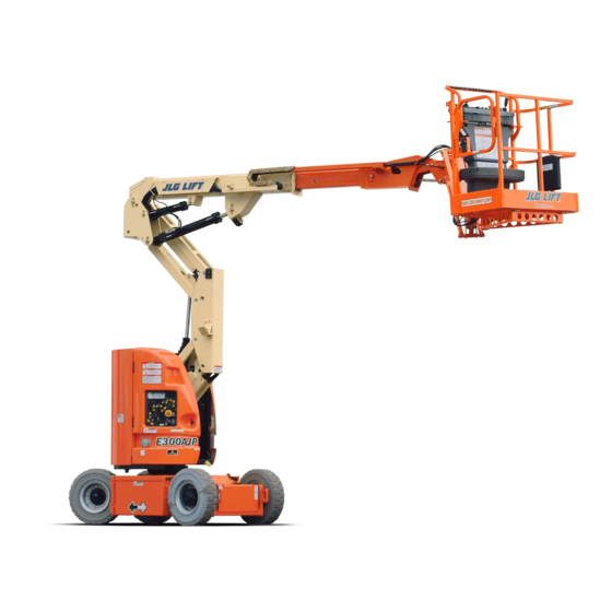
- Page 33 SECTION 2 - USER RESPONSIBILITIES, MACHINE PREPARATION, AND INSPECTION 9. Battery Box 1. Platform 10. Drive Hub 2. Platform Console 11. Ground Console 3. Jib Rotator (E300AJP Only) 12. Powertrack 4. Boom Fly Section 13. Jib 5. Main Boom 14. Platform Rotator 6.
-
Page 34: Pre-Start Inspection
SECTION 2 - USER RESPONSIBILITIES, MACHINE PREPARATION, AND INSPECTION Pre-Start Inspection 4. Operation and Safety Manuals – Make sure a copy of the Operator and Safety Manual, AEM Safety Manual (ANSI mar- The Pre-Start Inspection should include each of the following: kets only), and ANSI Manual of Responsibilities (ANSI mar- kets only) is enclosed in the weather resistant storage 1. -
Page 35: Daily Walk-Around Inspection
SECTION 2 - USER RESPONSIBILITIES, MACHINE PREPARATION, AND INSPECTION Daily Walk-Around Inspection 3121719... - Page 36 SECTION 2 - USER RESPONSIBILITIES, MACHINE PREPARATION, AND INSPECTION General 5. Wheel/Tire Assemblies - Properly secured, no missing lug nuts. Inspect for worn tread, cuts, tears or other discrepan- cies. Inspect wheels for damage and corrosion. Begin the "Walk-Around Inspection" at Item 1, as noted on the diagram.
-
Page 37: Function Check
SECTION 2 - USER RESPONSIBILITIES, MACHINE PREPARATION, AND INSPECTION Function Check 3. With the platform in the stowed position: a. Drive the machine on a grade, not to exceed the rated Perform the Function Check as follows: gradeability, and stop to ensure the brakes hold; 1. -
Page 38: Skyguard Function Test
SECTION 2 - USER RESPONSIBILITIES, MACHINE PREPARATION, AND INSPECTION SkyGuard Function Test 4. Disengage the SkyGuard sensor, release controls, then recy- cle the footswitch. Ensure normal operation is available. NOTE: Refer to Section 4.10 for additional information on SkyGuard NOTE: On machines equipped with SkyLine, reattach magnetic end of operation. - Page 39 TO PURCHASE THIS PRODUCT PLEASE CONTACT US Equipment Financing and Extended Warranties Available Discount-Equipment.com is your online resource for commercial and industrial quality parts and equipment sales. 561-964-4949 visit us on line @ www.discount-equipment.com Select an option below to find your Equipment We sell worldwide for the brands: Genie, Terex, JLG, MultiQuip, Mikasa, Essick, Whiteman, Mayco, Toro Stone, Diamond Products, Generac Magnum, Airman, Haulotte, Barreto, Power Blanket, Nifty Lift, Atlas Copco, Chicago Pneumatic, Allmand, Miller Curber, Skyjack, Lull,...
-
Page 40: Section 3 - Machine Controls And Indicators
SECTION 3 - MACHINE CONTROLS AND INDICATORS SECTION 3. MACHINE CONTROLS AND INDICATORS GENERAL NOTE: The indicator panels use different shaped symbols to alert the operator to different types of operational situations that could arise. The meaning of those symbols are explained below. Indicates a potentially hazardous situation, which if THE MANUFACTURER HAS NO DIRECT CONTROL OVER MACHINE APPLICATION AND not corrected, could result in serious injury or death. -
Page 41: Ground Control Station
SECTION 3 - MACHINE CONTROLS AND INDICATORS 1. Battery Charge Status Three LED lights indicate charge status of TO AVOID SERIOUS INJURY, DO NOT OPERATE MACHINE IF ANY CONTROL LEVERS OR battery. Green; indicates 100% charged. TOGGLE SWITCHES CONTROLLING PLATFORM MOVEMENT DO NOT RETURN TO THE Yellow;... - Page 42 SECTION 3 - MACHINE CONTROLS AND INDICATORS 1. Battery Charge Status 2. Function Enable 3. Main Boom Lift 4. Lower Boom Lift 5. Swing 6. Platform/Ground Select 7. Power/Emergency Stop 8. Telescope 9. Jib Lift 10. Not Used 11. Platform Level 12.
- Page 43 SECTION 3 - MACHINE CONTROLS AND INDICATORS 1. Battery Charge Status 2. Function Enable 3. Main Boom Lift 4. Lower Boom Lift 5. Swing 6. Platform/Ground Select 7. Power/Emergency Stop 8. Telescope 9. Jib Lift 10. Not Used 11. Platform Level 12.
- Page 44 SECTION 3 - MACHINE CONTROLS AND INDICATORS 1. Battery Charge Status 2. Function Enable 3. Main Lift 4. Lower Lift 5. Swing 6. Platform/Ground Select 7. Power/Emergency Stop 8. Telescope 9. Jib Lift 10. Jib Swing 11. Platform Level 12. Platform Rotate 13.
- Page 45 SECTION 3 - MACHINE CONTROLS AND INDICATORS 1. Battery Charge Status 2. Function Enable 3. Main Lift 4. Lower Lift 5. Swing 6. Platform/Ground Select 7. Power/Emergency Stop 8. Telescope 9. Jib Lift 10. Jib Swing 11. Platform Level 12. Platform Rotate 13.
- Page 46 SECTION 3 - MACHINE CONTROLS AND INDICATORS 4. Lower Boom Lift NOTE: When the Platform/Ground Select Switch is in the center posi- tion, power is shut off to the controls at both operating stations. Provides raising and lowering of the Remove the key to prevent the controls from being actuated.
- Page 47 SECTION 3 - MACHINE CONTROLS AND INDICATORS 9. Jib Lift Provides raising and lowering of the WHEN THE MACHINE IS SHUT DOWN THE POWER/EMERGENCY STOP SWITCH MUST BE jib. POSITIONED TO THE OFF POSITION TO PREVENT DRAINING THE BATTERIES. 7. Power/Emergency Stop Switch A two-position red mushroom shaped 10.
- Page 48 SECTION 3 - MACHINE CONTROLS AND INDICATORS 13. Platform Overload (If equipped) Indicates the platform has been over- ONLY USE THE PLATFORM LEVELING OVERRIDE FUNCTION FOR SLIGHT LEVELING OF loaded. THE PLATFORM. INCORRECT USE COULD CAUSE THE LOAD/OCCUPANTS TO SHIFT OR FALL.
-
Page 49: Platform Station
SECTION 3 - MACHINE CONTROLS AND INDICATORS Platform Station ONLY USE THE PLATFORM LEVELING OVERRIDE FUNCTION FOR SLIGHT LEVELING OF (See Figure 3-5., Platform Control Console) THE PLATFORM. INCORRECT USE COULD CAUSE THE LOAD/OCCUPANTS TO SHIFT OR FALL. FAILURE TO DO SO COULD RESULT IN DEATH OR SERIOUS INJURY. 2. - Page 50 SECTION 3 - MACHINE CONTROLS AND INDICATORS 1. Speed Mode 5. Drive Orientation Override 9. SkyGuard Override 13. Platform Rotate 2. Platform Leveling Override 6. Drive/Steer 10. Jib Swing 14. Function Speed 3. Horn 7. Telescope 11. Lower Boom Lift 15.
- Page 51 SECTION 3 - MACHINE CONTROLS AND INDICATORS 4. Power/Emergency Stop Switch NOTE: To operate the Drive joystick, pull up on the lock- ing ring below the handle. A two-position red mushroom shaped switch furnishes power to PLATFORM Con- NOTE: The Drive joystick is spring loaded and will auto- trols when pulled out (on).
- Page 52 SECTION 3 - MACHINE CONTROLS AND INDICATORS 8. Jib 12. SkyGuard Indicator (If Equipped) Provides for raising or lowering of the jib by Indicates the SkyGuard sensor has been activated. All con- positioning up/down. trols are cut out until the override button is pushed. Controls will then work normally.
- Page 53 SECTION 3 - MACHINE CONTROLS AND INDICATORS NOTE: To operate the Main Boom Lift/Swing joystick, pull up on the locking ring below the handle. NOTE: The Main Boom Lift/Swing joystick is spring loaded and will automatically return to neutral (off) position when released. 15.
-
Page 54: Platform Control Indicator Panel
SECTION 3 - MACHINE CONTROLS AND INDICATORS Platform Control Indicator Panel 2. Platform Overload (If equipped) Indicates the platform has been overloaded. (See Figure 3-6., Platform Control Indicator Panel) 1. Tilt Alarm Warning Light and Alarm Tilt Angle Market 3° CE &... - Page 55 SECTION 3 - MACHINE CONTROLS AND INDICATORS 1. Tilt 4. Drive Orientation 7. Low Battery 2. Platform Overload 5. Enable 8. SkyGuard 3. System Distress 6. Battery Charge 9. Creep Figure 3-6. Platform Control Indicator Panel 3-16 3121719...
- Page 56 SECTION 3 - MACHINE CONTROLS AND INDICATORS 3. System Distress Indicator flashes followed by a pause followed by another num- ber of flashes, and refer to the service manual. The system distress indicator lights to signify 4. Drive Orientation Indicator an electrical system fault.
- Page 57 SECTION 3 - MACHINE CONTROLS AND INDICATORS 5. Enable Indicator/Footswitch 6. Battery Charge Indicator To operate any function, the footswitch This indicator lights to show the state-of- must be depressed and the function charge of the battery pack.. selected within seven seconds. The enable indicator shows that the controls are enabled.
- Page 58 SECTION 3 - MACHINE CONTROLS AND INDICATORS 8. SkyGuard (If Equipped) 9. Creep Speed Indicator When illuminated indicates the SkyGuard When the Function Speed Control is sensor has been activated. All controls are turned to the creep position, the indicator cut out until the override button is pushed, acts as a reminder that all functions are set at which time controls will work normally.
- Page 59 TO PURCHASE THIS PRODUCT PLEASE CONTACT US Equipment Financing and Extended Warranties Available Discount-Equipment.com is your online resource for commercial and industrial quality parts and equipment sales. 561-964-4949 visit us on line @ www.discount-equipment.com Select an option below to find your Equipment We sell worldwide for the brands: Genie, Terex, JLG, MultiQuip, Mikasa, Essick, Whiteman, Mayco, Toro Stone, Diamond Products, Generac Magnum, Airman, Haulotte, Barreto, Power Blanket, Nifty Lift, Atlas Copco, Chicago Pneumatic, Allmand, Miller Curber, Skyjack, Lull,...
-
Page 60: Section 4. Machine Operation
SECTION 4 - MACHINE OPERATION SECTION 4. MACHINE OPERATION DESCRIPTION BOOM OPERATING CHARACTERISTICS AND LIMITATIONS This machine is a self-propelled hydraulic personnel lift equipped with a work platform on the end of an elevating and rotating Capacities boom. The primary operator control station is in the platform. From this Raising boom above horizontal with or without any load in plat- control station, the operator can drive and steer the machine in form, is based on the following criteria:... - Page 61 SECTION 4 - MACHINE OPERATION MAIN BOOM MAIN BOOM FULLY EXTENDED HORIZONTAL LOWER BOOM MACHINE WILL "TIP OVER" IN THIS FULLY ELEVATED DIRECTION IF OVERLOADED OR OPERATED ON AN OUT-OF-LEVEL SURFACE Figure 4-1. Position of Least Forward Stability 3121719...
- Page 62 SECTION 4 - MACHINE OPERATION MACHINE WILL "TIP OVER" IN THIS DIRECTION IF OVERLOADED OR OPERATED ON AN OUT-OF-LEVEL SURFACE MAIN BOOM FULLY ELEVATED AND FULLY RETRACTED LOWER BOOM FULLY ELEVATED Figure 4-2. Position of Least Backward Stability - E300AJ 3121719...
- Page 63 SECTION 4 - MACHINE OPERATION PLATFORM ROTATED 90 DEGREES MACHINE WILL "TIP OVER" IN THIS DIRECTION IF OVERLOADED OR OPERATED ON AN OUT-OF-LEVEL SURFACE MAIN BOOM FULLY ELEVATED AND FULLY RETRACTED LOWER BOOM FULLY ELEVATED Figure 4-3. Position of Least Backward Stability - E300AJP 3121719...
-
Page 64: Motor Operation
SECTION 4 - MACHINE OPERATION MOTOR OPERATION Motor Activation Power/Emergency Stop Switch FOOTSWITCH MUST BE DEPRESSED PRIOR TO ACTIVATING ANY FUNCTION, OTHER- This red, mushroom-shaped switch provides WISE FUNCTION WILL NOT OPERATE. battery power to the Platform/Ground Select switch, when pulled out (on), for all machine The motor becomes activated and operates the desired function functions. -
Page 65: Traveling (Driving)
SECTION 4 - MACHINE OPERATION TRAVELING (DRIVING) Traveling is limited by two factors: 1. Gradeability, which is the percent of grade of the incline the See Figure 4-4., Grade and Side Slopes machine can climb. NOTE: Refer to the Operating Specifications table for Gradeability and 2. - Page 66 SECTION 4 - MACHINE OPERATION S ID E S L O P E G R A D E LE V E L Figure 4-4. Grade and Side Slopes 3121719...
-
Page 67: Traveling Forward And Reverse
SECTION 4 - MACHINE OPERATION Traveling Forward and Reverse 1. Match the black and white direction arrows on both platform con- trol panel and the chas- FOOTSWITCH MUST BE DEPRESSED PRIOR TO ACTIVATING ANY FUNCTION, OTHER- sis to determine the WISE FUNCTION WILL NOT OPERATE. -
Page 68: Traveling On A Grade
SECTION 4 - MACHINE OPERATION Traveling on a Grade STEERING Position thumb switch on Drive/Steer controller to RIGHT for When traveling a grade, maximum braking and traction are obtained steering right, or to LEFT for steering left. with the boom stowed, in position over the rear (drive) axle, and in line with the direction of travel. -
Page 69: Boom
SECTION 4 - MACHINE OPERATION BOOM TO AVOID A COLLISION AND INJURY IF PLATFORM DOES NOT STOP WHEN A CONTROL SWITCH OR LEVER IS RELEASED, REMOVE FOOT FROM FOOTSWITCH OR USE EMER- GENCY STOP SWITCH TO STOP THE MACHINE. A RED TILT WARNING LIGHT IS LOCATED ON THE CONTROL CONSOLE WHICH LIGHTS WHEN THE CHASSIS IS ON AN EXCESSIVE SLOPE. -
Page 70: Machine Safety System Override (Msso)(Ce Only)
SECTION 4 - MACHINE OPERATION MACHINE SAFETY SYSTEM OVERRIDE (MSSO)(CE SkyGuard ONLY) The Machine Safety System Override (MSSO) is used to override function controls for Emergency Platform Retrieval only. Refer to Section 5.7, Machine Safety System Override (MSSO)(CE Only)for operating procedures. 4.10 SKYGUARD OPERATION SkyGuard provides enhanced control panel protection. -
Page 71: Skyguard - Skyeye
SECTION 4 - MACHINE OPERATION SkyGuard - SkyEye Reattach magnetic end of cable to bracket if it becomes discon- nected. Operator passes through path of sensor beam. SkyGuard Function Table Tower Boom Drive Drive Tower Boom Boom Boom Basket Basket Steer Swing Lift... -
Page 72: 4.11 Shut Down And Park
SECTION 4 - MACHINE OPERATION 4.11 SHUT DOWN AND PARK 4.12 LIFTING AND TIE DOWN NOTE: When parking battery powered units overnight, batteries should (See Figure 4-6.) be charged in accordance with instructions in Section 6 to Lifting ensure readiness for following workday. 1. - Page 73 SECTION 4 - MACHINE OPERATION E300AJ/AJP 41.4”/1.04m 44.0”/1.11m 1001112461B Figure 4-6. Lifting and Tie Down Chart 4-14 3121719...
- Page 74 SECTION 4 - MACHINE OPERATION CENTER VERTICALLY BOTH SIDES BOTH SIDES BOTH HYD TANK VIEW SIDES INSIDE HOOD Figure 4-7. ANSI Decal Location Sheet 1 of 5 3121719 4-15...
- Page 75 SECTION 4 - MACHINE OPERATION BOTH SIDES BOTH SIDES Figure 4-8. ANSI Decal Location Sheet 2 of 5 4-16 3121719...
- Page 76 SECTION 4 - MACHINE OPERATION Figure 4-9. ANSI Decal Location Sheet 3 of 5 3121719 4-17...
- Page 77 SECTION 4 - MACHINE OPERATION 34 42 BOTH SIDES OF PLATFORM Figure 4-10. ANSI Decal Location Sheet 4 of 5 4-18 3121719...
- Page 78 SECTION 4 - MACHINE OPERATION BOTH SIDES Figure 4-11. ANSI Decal Location Sheet 5 of 5 3121719 4-19...
- Page 79 SECTION 4 - MACHINE OPERATION Item # ANSI Item # ANSI 1001176388-D 1001176388-D 1703798 1703804 1703805 1703813 1701500 1701504 1704277 1701509 1704412 1701529 1701642 1706126 1701644 1001121801 1001121814 1702155 3251243 1702300 3251813 1702391 1702361 1001110196 1001196811 1001110389 1702868 1001112461 1703797 1001212200 4-20 3121719...
- Page 80 SECTION 4 - MACHINE OPERATION Item # ANSI 1001176388-D 1705351 3121719 4-21...
- Page 81 SECTION 4 - MACHINE OPERATION HYD TANK VIEW INSIDE HOOD BOTH SIDES BOTH BOTH SIDES SIDES Figure 4-12. CE/Australia Decal Location Sheet 1 of 5 4-22 3121719...
- Page 82 SECTION 4 - MACHINE OPERATION Figure 4-13. CE/Australia Decal Location Sheet 2 of 5 3121719 4-23...
- Page 83 SECTION 4 - MACHINE OPERATION Figure 4-14. CE/Australia Decal Location Sheet 3 of 5 4-24 3121719...
- Page 84 SECTION 4 - MACHINE OPERATION BOTH SIDES OF PLATFORM Figure 4-15. CE/Australia Decal Location Sheet 4 of 5 3121719 4-25...
- Page 85 SECTION 4 - MACHINE OPERATION Figure 4-16. CE/Australia Decal Location Sheet 5 of 5 4-26 3121719...
- Page 86 SECTION 4 - MACHINE OPERATION Item # CE/Australia Item # CE/Australia 1001176391-E 1001176391-E 1705822 1701518 1705961 1705670 1701500 1704277 1701504 1704412 1701509 1701529 1706126 1701642 1701644 1705978 1702155 1702300 1001110196 1701517 1001112461 1702631 1001212200 1705828 1001196811 1705921 3121719 4-27...
- Page 87 SECTION 4 - MACHINE OPERATION Item # CE/Australia 1001176391-E 4-28 3121719...
- Page 88 SECTION 4 - MACHINE OPERATION BOTH SIDES HYD TANK VIEW BOTH INSIDE HOOD SIDES BOTH SIDES Figure 4-17. Japan Decal Location Sheet 1 of 5 3121719 4-29...
- Page 89 SECTION 4 - MACHINE OPERATION Figure 4-18. Japan Decal Location Sheet 2 of 5 4-30 3121719...
- Page 90 SECTION 4 - MACHINE OPERATION Figure 4-19. Japan Decal Location Sheet 3 of 5 3121719 4-31...
- Page 91 SECTION 4 - MACHINE OPERATION BOTH SIDES OF PLATFORM Figure 4-20. Japan Decal Location Sheet 4 of 5 4-32 3121719...
- Page 92 SECTION 4 - MACHINE OPERATION BOTH SIDES Figure 4-21. Japan Decal Location Sheet 5 of 5 3121719 4-33...
- Page 93 SECTION 4 - MACHINE OPERATION Item # Japan Item # Japan 1001176390-F 1001176390-F 1703932 1703950 1703938 1704342 1701500 1704277 1701504 1704412 1701509 1701529 1706126 1701642 1701644 1001121821 1001121808 1702155 1702300 1001113166 1702631 1001110196 1001196811 1001110389 1001112461 1703926 1001212200 4-34 3121719...
- Page 94 SECTION 4 - MACHINE OPERATION Item # Japan 1001176390-F 1705426 1703980 3121719 4-35...
- Page 95 SECTION 4 - MACHINE OPERATION BOTH SIDES HYD TANK VIEW INSIDE HOOD SIDE BOTH SIDES Figure 4-22. Korea Decal Location Sheet 1 of 5 4-36 3121719...
- Page 96 SECTION 4 - MACHINE OPERATION Figure 4-23. Korea Decal Location Sheet 2 of 5 3121719 4-37...
- Page 97 SECTION 4 - MACHINE OPERATION Figure 4-24. Korea Decal Location Sheet 3 of 5 4-38 3121719...
- Page 98 SECTION 4 - MACHINE OPERATION 1 34 BOTH SIDES OF PLATFORM Figure 4-25. Korea Decal Location Sheet 4 of 5 3121719 4-39...
- Page 99 SECTION 4 - MACHINE OPERATION Figure 4-26. Korea Decal Location Sheet 5 of 5 4-40 3121719...
- Page 100 SECTION 4 - MACHINE OPERATION Item # Korea Item # Korea 1001176482-D 1001176482-D 1703927 1703933 1703951 1703939 1704343 1701500 1701504 1704277 1701509 1704412 1701529 1701642 1701644 1001121918 1001121921 1702155 1702300 1001113509 1702631 1001110196 1001196811 1001110389 1001112461 1705969 1001212200 3121719 4-41...
- Page 101 SECTION 4 - MACHINE OPERATION Item # Korea 1001176482-D 1705427 1703981 4-42 3121719...
- Page 102 SECTION 4 - MACHINE OPERATION BOTH SIDES HYD TANK VIEW BOTH INSIDE HOOD SIDES BOTH SIDES Figure 4-27. Spanish Decal Location Sheet 1 of 5 3121719 4-43...
- Page 103 SECTION 4 - MACHINE OPERATION Figure 4-28. Spanish Decal Location Sheet 2 of 5 4-44 3121719...
- Page 104 SECTION 4 - MACHINE OPERATION Figure 4-29. Spanish Decal Location Sheet 3 of 5 3121719 4-45...
- Page 105 SECTION 4 - MACHINE OPERATION 1 35 BOTH SIDES OF PLATFORM Figure 4-30. Spanish Decal Location Sheet 4 of 5 4-46 3121719...
- Page 106 SECTION 4 - MACHINE OPERATION Figure 4-31. Spanish Decal Location Sheet 5 of 5 3121719 4-47...
- Page 107 SECTION 4 - MACHINE OPERATION Item # Spanish Item # Spanish 1001176483-D 1001176483-D 1703923 1703929 1703947 1703935 1704339 1701500 1701504 1704277 1701509 1704412 1701529 1701642 1706126 1701644 1001121805 1001121818 1702155 1702300 1001113171 1702631 1001110196 1001196811 1001110389 1704001 1001112461 4-48 3121719...
- Page 108 SECTION 4 - MACHINE OPERATION Item # Spanish 1001176483-D 1001212200 1705910 1703983 3121719 4-49...
- Page 109 SECTION 4 - MACHINE OPERATION HYD TANK VIEW BOTH INSIDE HOOD SIDES BOTH SIDES BOTH SIDES Figure 4-32. French Decal Location Sheet 1 of 5 4-50 3121719...
- Page 110 SECTION 4 - MACHINE OPERATION Figure 4-33. French Decal Location Sheet 2 of 5 3121719 4-51...
- Page 111 SECTION 4 - MACHINE OPERATION Figure 4-34. French Decal Location Sheet 3 of 5 4-52 3121719...
- Page 112 SECTION 4 - MACHINE OPERATION 1 37 BOTH SIDES OF PLATFORM Figure 4-35. French Decal Location Sheet 4 of 5 3121719 4-53...
- Page 113 SECTION 4 - MACHINE OPERATION Figure 4-36. French Decal Location Sheet 5 of 5 4-54 3121719...
- Page 114 SECTION 4 - MACHINE OPERATION Item # French Item # French 1001176561-D 1001176561-D 1704000 1703924 1703930 1703948 1703936 1704340 1701500 1701504 1704277 1701509 1704412 1701529 1701642 1706126 1701644 1001121803 1001121816 1702155 3251243 1702300 3251813 1001113169 1702631 1001110196 1001196811 3121719 4-55...
- Page 115 SECTION 4 - MACHINE OPERATION Item # French 1001176561-D 1001110389 1001112461 1001212200 1705429 1703984 1705514 4-56 3121719...
- Page 116 SECTION 4 - MACHINE OPERATION BOTH SIDES HYD TANK VIEW INSIDE HOOD BOTH SIDES Figure 4-37. Chinese Decal Location Sheet 1 of 5 3121719 4-57...
- Page 117 SECTION 4 - MACHINE OPERATION Figure 4-38. Chinese Decal Location Sheet 2 of 5 4-58 3121719...
- Page 118 SECTION 4 - MACHINE OPERATION Figure 4-39. Chinese Decal Location Sheet 3 of 5 3121719 4-59...
- Page 119 SECTION 4 - MACHINE OPERATION 1 36 Figure 4-40. Chinese Decal Location Sheet 4 of 5 4-60 3121719...
- Page 120 SECTION 4 - MACHINE OPERATION Figure 4-41. Chinese Decal Location Sheet 5 of 5 3121719 4-61...
- Page 121 SECTION 4 - MACHINE OPERATION Item # Chinese Item # Chinese 1001176595-D 1001176595-D 1703925 1703931 1703949 1703937 1704344 1701500 1701504 1704277 1701509 1704412 1701529 1701642 1706126 1701644 1001121810 1001121823 1702155 3251243 1702300 3251813 1001113168 1702631 1001110196 1001196811 1705968 1001110389 4-62 3121719...
- Page 122 SECTION 4 - MACHINE OPERATION Item # Chinese 1001176595-D 1001112461 1001212200 1705430 1703982 3121719 4-63...
- Page 123 SECTION 4 - MACHINE OPERATION BOTH SIDES HYD TANK VIEW INSIDE HOOD BOTH SIDES BOTH SIDES Figure 4-42. Portuguese Decal Location Sheet 1 of 5 4-64 3121719...
- Page 124 SECTION 4 - MACHINE OPERATION Figure 4-43. Portuguese Decal Location Sheet 2 of 5 3121719 4-65...
- Page 125 SECTION 4 - MACHINE OPERATION Figure 4-44. Portuguese Decal Location Sheet 3 of 5 4-66 3121719...
- Page 126 SECTION 4 - MACHINE OPERATION 1 35 BOTH SIDES OF PLATFORM Figure 4-45. Portuguese Decal Location Sheet 4 of 5 3121719 4-67...
- Page 127 SECTION 4 - MACHINE OPERATION Figure 4-46. Portuguese Decal Location Sheet 5 of 5 4-68 3121719...
- Page 128 SECTION 4 - MACHINE OPERATION Item # Portuguese Item # Portuguese 1001176488-D 1001176488-D 1703928 1703934 1703952 1703940 1704341 1701500 1701504 1704277 1701509 1704412 1701529 1701642 1706126 1701644 1001121920 1001121923 1702155 3251813 1702300 1001113170 1702631 1001110196 1001196811 1001110389 1704002 1001112461 3121719 4-69...
- Page 129 SECTION 4 - MACHINE OPERATION Item # Portuguese 1001176488-D 1001212200 1001113680 1703985 4-70 3121719...
- Page 130 TO PURCHASE THIS PRODUCT PLEASE CONTACT US Equipment Financing and Extended Warranties Available Discount-Equipment.com is your online resource for commercial and industrial quality parts and equipment sales. 561-964-4949 visit us on line @ www.discount-equipment.com Select an option below to find your Equipment We sell worldwide for the brands: Genie, Terex, JLG, MultiQuip, Mikasa, Essick, Whiteman, Mayco, Toro Stone, Diamond Products, Generac Magnum, Airman, Haulotte, Barreto, Power Blanket, Nifty Lift, Atlas Copco, Chicago Pneumatic, Allmand, Miller Curber, Skyjack, Lull,...
-
Page 131: Section 5 - Emergency Procedures
SECTION 5 - EMERGENCY PROCEDURES SECTION 5. EMERGENCY PROCEDURES GENERAL FOLLOWING ANY INCIDENT, THOROUGHLY INSPECT THE MACHINE AND TEST ALL This section explains the steps to be taken in case of an emer- FUNCTIONS FIRST FROM THE GROUND CONTROLS, THEN FROM THE PLATFORM CON- gency situation while operating. -
Page 132: Platform Or Boom Caught Overhead
SECTION 5 - EMERGENCY PROCEDURES Platform or Boom Caught Overhead EMERGENCY TOWING PROCEDURES If the platform or boom becomes jammed or snagged in over- Towing this machine is prohibited. However, provisions for mov- head structures or equipment, do the following: ing the machine have been incorporated. -
Page 133: Manual Descent System
SECTION 5 - EMERGENCY PROCEDURES MANUAL DESCENT SYSTEM (See Figure 5-1., Manual Descent Location) The manual descent system is used, in the event of total power fail- ure or in case the key is not accessible to the ground personnel, to lower the upper and lower booms using gravity. - Page 134 SECTION 5 - EMERGENCY PROCEDURES MANUAL DESCENT KNOB SPLIT RING Figure 5-1. Manual Descent Location 3121719...
-
Page 135: Manual Swing Override
SECTION 5 - EMERGENCY PROCEDURES MANUAL SWING OVERRIDE NOTE: No functional checks of the MSSO system are necessary. The JLG Control system will set a Diagnostic Trouble Code if the control switch is faulty. The manual swing override is used to manually swing the boom and turntable assembly in the event of a total power failure when the To operate the MSSO: platform is positioned over a structure or obstacle. - Page 136 SECTION 5 - EMERGENCY PROCEDURES NOTES: 3121719...
-
Page 137: Section 6 - Accessories
SECTION 6 - ACCESSORIES SECTION 6. ACCESSORIES Table 6-1. Available Accessories Market Accessory ANSI ANSI Japan China (USA Only) Pipe Racks √ 3121719... -
Page 138: Pipe Racks
SECTION 6 - ACCESSORIES PIPE RACKS Safety Precautions REDUCE PLATFORM CAPACITY BY 100 LBS (45.5 KG) WHEN INSTALLED. WEIGHT IN RACKS PLUS WEIGHT IN PLATFORM MUST NOT EXCEED RATED CAPACITY. THE MAXIMUM LOAD IN THE RACKS IS 180 LBS (80 KG) EVENLY DISTRIBUTED BETWEEN THE TWO RACKS. -
Page 139: Preparation And Inspection
SECTION 6 - ACCESSORIES Preparation and Inspection Operation • Ensure racks are secured to the platform rails. 1. To prepare racks for loading, remove locking pins, rotate each rack 90 degrees from stowed to working position, then • Replace torn or frayed tie-down straps. secure with locking pins. - Page 140 TO PURCHASE THIS PRODUCT PLEASE CONTACT US Equipment Financing and Extended Warranties Available Discount-Equipment.com is your online resource for commercial and industrial quality parts and equipment sales. 561-964-4949 visit us on line @ www.discount-equipment.com Select an option below to find your Equipment We sell worldwide for the brands: Genie, Terex, JLG, MultiQuip, Mikasa, Essick, Whiteman, Mayco, Toro Stone, Diamond Products, Generac Magnum, Airman, Haulotte, Barreto, Power Blanket, Nifty Lift, Atlas Copco, Chicago Pneumatic, Allmand, Miller Curber, Skyjack, Lull,...
-
Page 141: Section 7. General Specifications & Operator Maintenance
SECTION 7 - GENERAL SPECIFICATIONS & OPERATOR MAINTENANCE SECTION 7. GENERAL SPECIFICATIONS & OPERATOR MAINTENANCE INTRODUCTION OPERATING SPECIFICATIONS AND PERFORMANCE DATA This section of the manual provides additional necessary infor- mation to the operator for proper operation and maintenance of Operating Specifications this machine. - Page 142 SECTION 7 - GENERAL SPECIFICATIONS & OPERATOR MAINTENANCE Table 7-1. Operating specifications - E300AJ Table 7-2. Operating specifications - E300AJP Maximum System Voltage 48V DC Drive Speed Maximum 4.5 mph (7.2 kph) Maximum Main Relief Hyd. Pressure 3000 psi (207 bar) Reduced 3 mph (4.8 kph) Elevated...
-
Page 143: Dimensional Data
SECTION 7 - GENERAL SPECIFICATIONS & OPERATOR MAINTENANCE Dimensional Data Table 7-4. Dimensional Data - E300AJP Table 7-3. Dimensional Data - E300AJ Turning Radius (Inside) 5 ft. (1.52 m) Turning Radius (Outside) 10ft. 2in. (3.1 m) Turning Radius (Inside) 5 ft. (1.52 m) Machine Height (stowed) 6ft. -
Page 144: Capacities
SECTION 7 - GENERAL SPECIFICATIONS & OPERATOR MAINTENANCE Capacities Hydraulic Oil Table 7-7. Hydraulic Oil Table 7-5. Capacities Hydraulic System Hydraulic Oil Tank 2.9 Gal. (11 L) S.A.E. Viscosity Operating 2.1 Gal. ( 8 L) to Full Mark Grade Temperature Range 25.5 oz. - Page 145 SECTION 7 - GENERAL SPECIFICATIONS & OPERATOR MAINTENANCE NOTE: Aside from JLG recommendations, it is not advisable to mix oils Table 7-9. DTE 10 Excel 15 Specs of different brands or types, as they may not contain the same required additives or be of comparable viscosities. If use of ISO Viscosity Grade hydraulic oil other than Mobil DTE 11M is desired, contact JLG Pour Point, Max...
- Page 146 SECTION 7 - GENERAL SPECIFICATIONS & OPERATOR MAINTENANCE Table 7-11. Mobil EAL 224H Specs Table 7-10. Mobilfluid 424 Specs SAE Grade 10W30 Type Biodegradable Vegetable Oil Gravity, API 29.0 ISO Viscosity Grade 32/46 Density, Lb/Gal. 60°F 7.35 Specific Gravity .922 Pour Point, Max -46°F (-43°C) Pour Point, Max...
- Page 147 SECTION 7 - GENERAL SPECIFICATIONS & OPERATOR MAINTENANCE Table 7-12. Mobil EAL Envirosyn H Specs Table 7-13. Quintolubric 888-46 Density Type Synthetic Biodegradable 0.92 g/cm ISO Viscosity Grade Pour Point <-30°C (<-22°F) Specific Gravity .950 Flash Point 300°C (572°F) Pour Point, Max -59°F (-51°C) Fire Point 360°C (680°F)
-
Page 148: Major Component Weights
SECTION 7 - GENERAL SPECIFICATIONS & OPERATOR MAINTENANCE Major Component Weights DO NOT REPLACE ITEMS CRITICAL TO STABILITY WITH ITEMS OF DIFFERENT WEIGHT OR SPECIFICATION (FOR EXAMPLE: BATTERIES, FILLED TIRES, PLATFORM) DO NOT MODIFY UNIT IN ANY WAY TO AFFECT STABILITY. Table 7-14. - Page 149 SECTION 7 - GENERAL SPECIFICATIONS & OPERATOR MAINTENANCE Figure 7-1. Operator Maintenance and Lubrication Diagram 3121719...
-
Page 150: Operator Maintenance
SECTION 7 - GENERAL SPECIFICATIONS & OPERATOR MAINTENANCE OPERATOR MAINTENANCE 1. Swing Bearing NOTE: The following numbers correspond to those in Figure 7-1., Oper- ator Maintenance and Lubrication Diagram. Table 7-15. Lubrication Specifications. SPECIFICATIONS Multipurpose Grease having a minimum dripping point of 350 degrees F. Excellent water resistance and adhesive qualities;... - Page 151 SECTION 7 - GENERAL SPECIFICATIONS & OPERATOR MAINTENANCE 2. Swing Bearing/Worm Gear Teeth Lube Point(s) - Grease Fitting Lube Point(s) - Grease Fitting Capacity - A/R Capacity - A/R Lube - Mobile SHC 007 Lube - BG Interval - A/R Interval - A/R DO NOT OVERGREASE BEARINGS.
- Page 152 SECTION 7 - GENERAL SPECIFICATIONS & OPERATOR MAINTENANCE 3. Hydraulic Tank 4. Hydraulic Return Filter Lube Point(s) - Fill Cap Interval - Change after first 50 hrs. and every 6 months or 300 Capacity - 2.9 Gal. (11 L), 2.1 Gal. ( 8 L) to Full Mark hrs.
- Page 153 SECTION 7 - GENERAL SPECIFICATIONS & OPERATOR MAINTENANCE 5. Wheel Drive Hub 6. Wheel Bearings O IL LE V E L C H E C K A N D F ILL Lube Point(s) - Repack Lube Point(s) - Level/Fill Plug Capacity - A/R Capacity - 25.5 oz.
-
Page 154: Battery Maintenance And Charging
SECTION 7 - GENERAL SPECIFICATIONS & OPERATOR MAINTENANCE BATTERY MAINTENANCE AND CHARGING 2. Remove all vent caps and inspect electrolyte level of each cell. Electrolyte level should be to the ring approximately one inch from top of battery. Fill batteries with distilled water only. -
Page 155: Battery Charging, Daily
SECTION 7 - GENERAL SPECIFICATIONS & OPERATOR MAINTENANCE Battery Charging, Daily c. Allow batteries to charge until 100% LED is illuminated. NOTE: When batteries are completely charged, disconnect charging NOTE: To avoid excessive battery charging time, do not allow batteries harness cable from receptacle. -
Page 156: Tires & Wheels
SECTION 7 - GENERAL SPECIFICATIONS & OPERATOR MAINTENANCE TIRES & WHEELS Wheel and Tire Replacement Tire Replacement The rims installed on each product model have been designed for stability requirements which consist of track width, tire pressure, and load capacity. Size changes such as rim width, center piece location, JLG recommends a replacement tire be the same size, ply and brand larger or smaller diameter, etc., without written factory recommen- as originally installed on the machine. -
Page 157: Supplemental Information
SECTION 7 - GENERAL SPECIFICATIONS & OPERATOR MAINTENANCE 1. Start all nuts by hand to prevent cross threading. DO NOT 4. Wheel nuts should be torqued after first 50 hours of opera- use a lubricant on threads or nuts. tion and after each wheel removal. Check the torque after the first 10 miles, 25 miles, and again at 50 miles. - Page 158 SECTION 7 - GENERAL SPECIFICATIONS & OPERATOR MAINTENANCE NOTES: 7-18 3121719...
-
Page 159: Section 8 - Inspection And Repair Log
SECTION 8 - INSPECTION AND REPAIR LOG SECTION 8. INSPECTION AND REPAIR LOG Machine Serial Number _______________________________________ Table 8-1. Inspection and Repair Log Date Comments 3121719... - Page 160 TO PURCHASE THIS PRODUCT PLEASE CONTACT US Equipment Financing and Extended Warranties Available Discount-Equipment.com is your online resource for commercial and industrial quality parts and equipment sales. 561-964-4949 visit us on line @ www.discount-equipment.com Select an option below to find your Equipment We sell worldwide for the brands: Genie, Terex, JLG, MultiQuip, Mikasa, Essick, Whiteman, Mayco, Toro Stone, Diamond Products, Generac Magnum, Airman, Haulotte, Barreto, Power Blanket, Nifty Lift, Atlas Copco, Chicago Pneumatic, Allmand, Miller Curber, Skyjack, Lull,...
Need help?
Do you have a question about the JLG E300AJ and is the answer not in the manual?
Questions and answers