Table of Contents
Advertisement
Quick Links
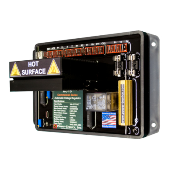
XC14
Commercial Series
Automatic Voltage Regulator
(From Serial # 624893)
The Power-Tronics XC14 voltage regulator is a
self-contained, highly integrated, heavy-duty
voltage regulator designed for demanding
applications and extremely flexible installations.
Continuous output is rated at 32/63VDC @
12ADC with forcing output up to 52/105VDC @
20ADC!
The modern generator service technician is often
presented with a variety of generator applications,
all of which require different voltage regulators,
features, or buildup considerations. The XC14 is
explicitly designed with the service technician in
mind, packing an impressive collection of features
in a compact and reliable package with simple
installation and setup instructions!
Standard integrated features of the XC14 include
onboard fusing, heavy duty rectifier section,
integrated 0-10V at 4-20mA control interface, built
in paralleling provisions, and a durable voltage
regulator.
Over 30 years of design refinement makes the
XC14 a durable design, utilizing high-reliability
components and a simple layout. Our products
are designed to provide a lifetime of service and
is specifically built to minimize failures and
potential downtime!
The XC14 are capable of parallel operation with
other generators or with a utility buss. The
integrated 0-10VDC or 4-20mA interface allows a
wide variety of VAR, PF, or other PLC controls to
remotely control the unit for extreme accuracy
and unattended installations.
A heavy duty rectifier section, oversized heatsink
and flexible hookup design makes the XC14 an
ideal aftermarket replacement AVR for
applications such as Caterpillar, Leroy Somer,
General Electric, EM BeMac, Onan Magnaciter,
SDMO, Marelli, Mecc-Alte and many others!
© 2020 Power-Tronics, Inc.
Specifications
Input/Sensing Voltage:
Frequency:
Voltage Regulation:
Parallel Operation
Continuous Rated Output Voltage:
Maximum Forcing Output Voltage
Rated Continuous Output Amps:
Minimum Field Resistance:
Min Residual Build up Voltage:
Under Frequency Protection:
Physical Size:
Weight:
Internal Protection:
Fuse Type:
External Voltage Adjustment:
System Operating Indicator:
Integrated 0-10VDC / 4-20mA Interface:
100 - 277vac
50 or 60 Hz
± .5% From NL to FL
Yes
32vdc @ 120vac input
63vdc @ 240vac input
52vdc @ 120vac input
105vdc @ 240vac input
12adc
2.5Ω @ 120vac input
5Ω @ 240vac input
3.5vac
Yes, VPH reduction
7.25 x 4.75 x 3.5 in.
1.5 lb.
Fuses, cartridge type
Main: 3AG 20A @ 250V
Yes
Yes
Yes
Advertisement
Table of Contents

Related Manuals for Power-Tronics Commercial Series


Summary of Contents for Power-Tronics Commercial Series
- Page 1 XC14 Commercial Series Automatic Voltage Regulator (From Serial # 624893) The Power-Tronics XC14 voltage regulator is a self-contained, highly integrated, heavy-duty voltage regulator designed for demanding applications and extremely flexible installations. Continuous output is rated at 32/63VDC @ 12ADC with forcing output up to 52/105VDC @...
-
Page 2: Table Of Contents
277V Input Power & Field Connection Diagram (Line-Neutral):.......10 Current Transformer Wiring Diagram (Paralleled Generators):.......11 Fully Automatic Remote Adjustment Wiring Diagram:..........12 Automatic / Manual Selectable Remote Adjustment Wiring Diagram:....13 Initial Setup and Commissioning:................14 Application Troubleshooting:..................15 Bench Check Procedures:...................16 Installation Warranty Form:..................17 Product Warranty Certificate:..................18 © 2020 Power-Tronics, Inc. -
Page 3: Introduction And Functional Description
The XC14 is a time and field-proven design, based upon the Power-Tronics XR8 and SEM250A, and is engineered to greatly simplify setup while offering extreme reliability. When properly installed, the XC14 Voltage regulator is designed to provide a lifetime of service. -
Page 4: Determining Application Sizing
OIL CONTAMINATION ON BRUSHES OR SLIP RINGS • DULL, ROUGH, STRIPED, PITTED, OR METALLIC APPEARANCE OF BRUSH FACES • FIELD RESISTANCE MEASURED BETWEEN SLIP RING BRASS AND FIELD RESISTANCE MEASURED BETWEEN FIELD LEADS EXCEEDS 1-2% DIFFERENCE © 2020 Power-Tronics, Inc. - Page 5 R is your measured field resistance. Using the values you just measured and calculated, see the specifications on the previous page to determine whether the XC14 is the correct product for your application. © 2020 Power-Tronics, Inc.
-
Page 6: Common 12-Lead Generator Terminal Diagrams
Voltage L1/L2-N: 120V Preferred Single-Phase Connection. Voltage L3 – N: 208V Don’t Use Zig-Zag if Possible. NOTE: L3-N is a “High Leg” NOTE: Derate generator by 1/3 rated 208V instead of 120V! capacity when using this connection! © 2020 Power-Tronics, Inc. -
Page 7: Iso Standard" 12-Lead Generator Terminal Diagrams
Voltage U/W-N: 120V Preferred Single-Phase Connection. Voltage V – N: 208V Don’t Use Zig-Zag if Possible. NOTE: V-N is a “High Leg” NOTE: Derate generator by 1/3 rated 208V instead of 120V! capacity when using this connection! © 2020 Power-Tronics, Inc. -
Page 8: 120V Input Power & Field Connection Diagram
R1 and R2 if not NOTE: paralleled! using the Remote Use switch rated: Voltage Adjustment! 20A @ 250VAC See Page 11 for Paralleling Wire Diagram See Pages 12-13 for External Control Wiring Diagrams © 2020 Power-Tronics, Inc. -
Page 9: 240V Input Power & Field Connection Diagram
R1 and R2 if not NOTE: paralleled! using the Remote Use switch rated: Voltage Adjustment! 20A @ 250VAC See Page 11 for Paralleling Wire Diagram See Pages 12-13 for External Control Wiring Diagrams © 2020 Power-Tronics, Inc. -
Page 10: 277V Input Power & Field Connection Diagram (Line-Neutral)
R1 and R2 if not NOTE: paralleled! using the Remote Use switch rated: Voltage Adjustment! 20A @ 480VAC See Page 11 for Paralleling Wire Diagram See Pages 12-13 for External Control Wiring Diagrams © 2020 Power-Tronics, Inc. -
Page 11: Current Transformer Wiring Diagram (Paralleled Generators)
NOTE: Power-Tronics products parallel using the Reactive Droop compensation method. This allows our products to parallel with existing systems easily while also allowing islanded operation with the flip of a switch. When initially installing the droop resistor, set it for approximately 7Ω before final adjustment later. -
Page 12: Fully Automatic Remote Adjustment Wiring Diagram
This wiring diagram shows ONLY the control wiring configuration for fully-automatic Remote Control of the XC14. Power wiring is shown on Pages 8-10. 0-10VDC NOTE: Colored Wires are for ease of identification in 4-20mA this drawing only, they Control Signal are not required © 2020 Power-Tronics, Inc. -
Page 13: Automatic / Manual Selectable Remote Adjustment Wiring Diagram
Remote Control of the XC14. Power wiring is shown on Pages 8-10. Switch Position: Automatic é 100KΩ @ 2w Manual ê NOTE: Colored Wires are for ease of identification in this drawing only, they are not required 0-10VDC 4-20mA Control Signal DPDT Switch or Relay © 2020 Power-Tronics, Inc. -
Page 14: Initial Setup And Commissioning
The unit will recognize 0-10V control signals and will ignore any negative control signals. Observe voltage regulation during no-load and full-load conditions. Once the voltage is set and regulating characteristics are satisfactory the installation procedure is complete. © 2020 Power-Tronics, Inc. -
Page 15: Application Troubleshooting
22. Damaged, pitted, or grooved slip ring surface. 23. Current transformer has reversed polarity or is not shorted during non-parallel operation. 24. Input to regulator is from an auxiliary winding and not the generator main stator. © 2020 Power-Tronics, Inc. -
Page 16: Bench Check Procedures
If you were able to successfully perform all of these tests, the XC14 is good. 120V 50-150W 120-240VAC Incandescent Fused @ 5A Jumper Fuse Replacement Information: XC14 Main: Rating: 20A @ 250VAC Qty: 1 PTI Part # 5R3-628 Littelfuse Part # 0314020.MXP © 2020 Power-Tronics, Inc. -
Page 17: Installation Warranty Form
It is very important that you fill out this form completely when installing a voltage regulator. This form serves as a history record on the application. This form also contains the information needed by Power-Tronics, Inc., for repair and troubleshooting of any product you may be having problems with. -
Page 18: Product Warranty Certificate
These problems should be protected with external devices provided by the customer such as fuses, surge suppressors, over/under voltage and frequency controls. Power-Tronics, Inc., warranties only parts and workmanship of this product for a period of 1 year from the original date of purchase from Power-Tronics, Inc. Under warranty, Power- Tronics, Inc.
Need help?
Do you have a question about the Commercial Series and is the answer not in the manual?
Questions and answers