Table of Contents
Advertisement
Quick Links
Specifications
Input Voltage:
Frequency:
Voltage Regulation:
Parallel Operation
Maximum Output Voltage:
Continuous Output Voltage:
Maximum Continuous Output:
Minimum Field Resistance:
Min Residual Build up Voltage:
Under Frequency Protection:
Physical Size:
Weight:
Repairable:
Internal Protection:
External Voltage Adjustment:
System Operating Indicator:
Optional Static Exciter Modules:
Optional External Controls:
Cartridge Fuse Type:
Optional External Potentiometer:
External Adjustment Range:
120 / 208 or 240vac
50 or 60hz
± .25% From NL to FL
Yes
52vdc @ 120vac input
105vdc @ 240vac input
210vdc @ 240vac input
32vdc @ 120vac input
63vdc @ 240vac input
125vdc @ 240vac input
8adc
6.5Ω @ 32vdc output
13Ω @ 63vdc output
26Ω @ 125vdc output
3.5vac
Yes, VPH reduction
4.75 x 6 x 1 in.
7 oz
Yes
Fuses, cartridge type
Yes
Yes
Yes
Yes
3AG 10A @ 250V Fast-Blow
100KΩ @ 2W
±10% of Terminal Voltage
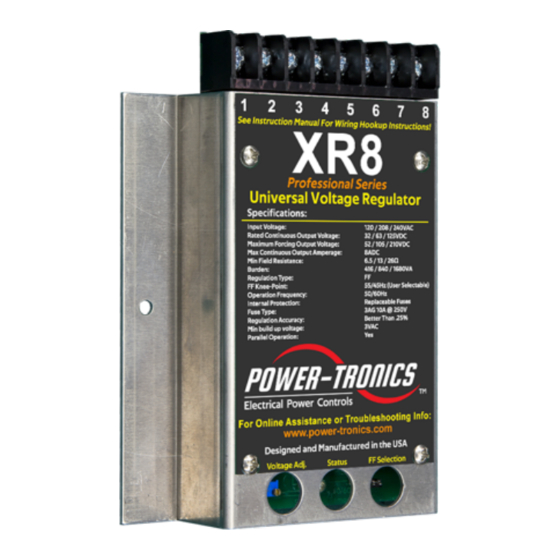
XR8
Professional Series
Universal Voltage Regulator
REVISION A (or later)
The Power-Tronics XR8 Universal Voltage
Regulator is the latest upgrade for all UVR and
XR series voltage regulators and features an
upgraded regulation system and a higher
amperage rectifier section capable of 8 amps!
The XR8 is also capable of replacing other
manufacturers' voltage regulators and has
optional Static Exciter Modules to boost its
capacity to 30 amps DC!
The XR8 is designed specifically for Professional
Electrical Generator Service Technicians and
the Electrical Generator Repair Industry. It
incorporates an easily selectable frequency
range for voltage roll-off during under-frequency
operation and offers precise voltage regulation
regardless of the connected load and ambient
temperature. The XR8 is a ruggedized design
and is engineered to provide a lifetime of
trouble-free, reliable operation.
Manual stability matching is a thing of the past,
the XR8 contains patented electronic circuitry
that automatically matches the regulator's
response time to the generator exciter. This
greatly speeds installation and eliminates
guesswork.
PLC and automated Genset control is possible
with the XR8 by simply adding an optional,
inexpensive digital interface module. This
capability makes the XR8 suitable for automated
or unattended installations, or large-scale
parallel operations.
Like our previous models, the XR8 is fully
repairable! All major electronic components are
not encapsulated to facilitate repair while all
sensitive components are encapsulated to
protect them from contamination and moisture.
The XR8 is compatible with all previous and
current optional modules available for use with
Power-Tronics voltage regulators making it
extremely simple to upgrade an existing voltage
regulator installation.
© 2020 Power-Tronics, Inc.
Advertisement
Table of Contents

Related Manuals for Power-Tronics Professional Series


Summary of Contents for Power-Tronics Professional Series
- Page 1 Professional Series Universal Voltage Regulator REVISION A (or later) The Power-Tronics XR8 Universal Voltage Regulator is the latest upgrade for all UVR and XR series voltage regulators and features an upgraded regulation system and a higher amperage rectifier section capable of 8 amps!
-
Page 2: Table Of Contents
Hookup Connection B:....................10 Parallel Configuration for Connection B:..............11 Hookup Connection C:....................12 Parallel Configuration for Connection C:..............13 Initial Setup and Commissioning:................14 Optional Power-Tronics Add-On Modules:..............15 Conversion From Shunt-Wound to Solid-State Regulation:........16 Internal Fuse Replacement:..................17 Application Troubleshooting:..................18 Bench Check Procedures:...................19 Installation Warranty Form:..................20... -
Page 3: Introduction And Functional Description
Introduction and Functional Description Caution: Read This Installation Manual Carefully and Entirely! Warning: Do not use digital equipment to read voltage, Hz, or amperage during this installation. Use only Analog sensing equipment! Failure to do so may result in damage to equipment or in personal injury! ALWAYS perform all setup procedures off-line ALWAYS wear eye protection... -
Page 4: Determining Which Hookup Configuration To Use
Determining Which Hookup Configuration to Use STOP! If you are using an optional SEM250A/B or SE350/450 Static Exciter Module, DO NOT use these instructions for hookup! See the instructions that came with your module instead! The XR8 Universal Voltage Regulator is configurable for 3 different output ranges suitable for use on the vast majority of generators available on the market from past and present. - Page 5 If you do not have any of the specifications of your generator’s exciter, or if you don’t know where to start when trying to determine your exciter specs, please see the section below for instructions on measuring and calculating your exciter specifications.
-
Page 6: Common 12-Lead Generator Wiring Diagrams
Common 12-Lead Generator Wiring Diagrams Parallel Wye (208/240V 3ø) Series Wye (416/480V 3ø) Voltage L-L: 208/240V Voltage L-L: 416/480V Voltage L-N: 120/139V Voltage L-N: 240/277V NOTE: 208V is Standard Voltage Voltage CT – N: 120/139V Double-Delta (120/240V 1ø) Series Delta (240V 3ø) Voltage L-L: 240V Voltage L-L: 240V Voltage L-N: 120V... -
Page 7: Use With Pmgs, Dpe, Aux, And Harmonic Winding Generators
PMG, DPE Winding, Auxiliary Winding, and Harmonic/Resonant Winding Use The XR8 Universal Voltage Regulator is compatible with some of these types of generators but not others. It is necessary to determine which type of generator you have before proceeding since some styles will connect differently than others while the XR8 cannot be used with some of these generators at all. -
Page 8: Hookup Connection A
240V @ 10A NOTE: It is not necessary to jumper terminals 7 and 8 if not using XR8 Professional Series the Remote Voltage Universal Voltage Regulator Adjustment! NOTE: If the generator is to be operated below 50/60 Hz, a disconnect or switch should be installed in series with the incoming power to terminals #1 and #2 on the XR8. -
Page 9: Parallel Configuration For Connection A
Connection A. NOTE: Power-Tronics products parallel using the Reactive Droop compensation method. This allows our products to parallel with existing systems easily while also allowing islanded operation with the flip of a switch. When initially installing the droop resistor, set it for approximately 7Ω before final adjustment later. If the droop is excessive when load testing, reduce the resistance a bit at a time until satisfactory droop is achieved. -
Page 10: Hookup Connection B
240V @ 10A NOTE: It is not necessary to jumper terminals 7 and 8 if not using XR8 Professional Series the Remote Voltage Universal Voltage Regulator Adjustment! NOTE: If the generator is to be operated below 50/60 Hz, a disconnect or switch should be installed in series with the incoming power to terminals #1 and #2 on the XR8. -
Page 11: Parallel Configuration For Connection B
Connection B. NOTE: Power-Tronics products parallel using the Reactive Droop compensation method. This allows our products to parallel with existing systems easily while also allowing islanded operation with the flip of a switch. When initially installing the droop resistor, set it for approximately 7Ω before final adjustment later. If the droop is excessive when load testing, reduce the resistance a bit at a time until satisfactory droop is achieved. -
Page 12: Hookup Connection C
240V @ 10A NOTE: It is not necessary to jumper terminals 7 and 8 if not using XR8 Professional Series the Remote Voltage Universal Voltage Regulator Adjustment! NOTE: If the generator is to be operated below 50/60 Hz, a disconnect or switch should be installed in series with the incoming power to terminals #1 and #2 on the XR8. -
Page 13: Parallel Configuration For Connection C
Connection C. NOTE: Power-Tronics products parallel using the Reactive Droop compensation method. This allows our products to parallel with existing systems easily while also allowing islanded operation with the flip of a switch. When initially installing the droop resistor, set it for approximately 7Ω before final adjustment later. If the droop is excessive when load testing, reduce the resistance a bit at a time until satisfactory droop is achieved. -
Page 14: Initial Setup And Commissioning
Initial Setup and Commissioning 1. Install the regulator and wire according to the correct wiring diagram (Connection A, B, or C). 2. If installing the XR8 on a brush-type generator, verify that the brushes and brush riggings are isolated, ungrounded, and connected ONLY to the XR8. -
Page 15: Optional Power-Tronics Add-On Modules
Optional Power-Tronics Add-On Modules Power-Tronics offers a wide array of optional add-on modules for the XR series voltage regulators from static exciter modules to digital interface cards. For more information on any of the modules below, visit our online catalog at: www.power-tronics.com... -
Page 16: Conversion From Shunt-Wound To Solid-State Regulation
Conversion From Older Shunt-Wound Voltage Regulation to Modern Solid-State Voltage Regulation It is possible to use the XR8 Universal Voltage regulator with older Shunt-Wound exciters that originally had manual, mechanical, or series solid-state voltage regulators by converting the wiring as in the diagrams below. -
Page 17: Internal Fuse Replacement
To replace the fuses, follow the instructions below. Fuse size is 32mm x 6.3mm rated at 10A at 250VAC. Power-Tronics Part Number: 5R3-626 (Comes as a package of 10 fuses) Cooper-Bussmann Part Number: BK/ABC-10 or BK/ABC-10R Littelfuse Part Number: 0314010.MXP or 0314010.HXP... -
Page 18: Application Troubleshooting
Application Troubleshooting Problem: Possible Cause No Voltage 1 3 5 7 9 11 13 15 20 Pulsating Voltage 4 5 6 12 16 Flickering Voltage 4 6 7 14 High Voltage 6 7 8 9 12 13 17 18 20 Voltage Drop on Load 5 8 10 12 16 Low Voltage... -
Page 19: Bench Check Procedures
Bench Check Procedures 1. Wire the regulator as shown in Figure A below. 2. Connect a 120 volt 50 to 150 watt light bulb as shown. 3. Adjust the internal voltage pot fully CCW (25 turns) or until a click is heard. 4. -
Page 20: Installation Warranty Form
This form also contains the information needed by Power-Tronics, Inc., for repair and troubleshooting of any product you may be having problems with. Failure to fill out this form during installation will result in a cancellation of your warranty... -
Page 21: Product Warranty Certificate
These problems should be protected with external devices provided by the customer such as fuses, surge suppressors, over/under voltage and frequency controls. Power-Tronics, Inc., warranties only parts and workmanship of this product for a period of 3 years from the original date of purchase from Power-Tronics, Inc. Under warranty, Power- Tronics, Inc.
Need help?
Do you have a question about the Professional Series and is the answer not in the manual?
Questions and answers