Table of Contents
Advertisement
Quick Links
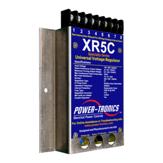
Specifications
Input Voltage:
Frequency:
Voltage Regulation:
Parallel Operation
Maximum Output Voltage:
Continuous Output Voltage:
Maximum Continuous Output:
Minimum Field Resistance:
Min Residual Build up Voltage:
Under Frequency Protection:
Physical Size:
Weight:
Repairable:
Internal Protection:
External Voltage Adjustment:
System Operating Indicator:
Optional Static Exciter Modules
Optional External Controls
Cartridge Fuse Type:
Optional External Potentiometer:
External Adjustment Range:
120 / 208 or 240vac
50 or 60hz
± 1% From NL to FL
Yes
52vdc @ 120vac input
105vdc @ 240vac input
210vdc @ 240vac input
32vdc @ 120vac input
63vdc @ 240vac input
125vdc @ 240vac input
5adc
10.5Ω @ 52vdc output
21Ω @ 105vdc output
42Ω @ 210vdc output
3.5vac
Yes, VPH reduction
4.75 x 6 x 1 in.
7 oz
Yes
Fuses, cartridge type
Yes
Yes
Yes
Yes
GDB 5A @ 250V Fast-Blow
100KΩ @ 2W
±10% of Terminal Voltage
XR5C
Specialty Series
Universal Voltage Regulator
The Power-Tronics XR5C Universal Voltage
Regulator is the latest upgrade to the XR500C
product line and features a strengthened
regulation system and a redesigned rectifier
section to match that of the XR8! The XR5C is
also capable of replacing other manufacturers'
voltage regulators and has optional Static Exciter
Modules to boost its capacity to 30 amps DC!
The XR5C is designed for legacy installations and
specialty applications where tolerance to extreme
waveform distortion is required or installations
where manual tuning of stability is preferred.
Manual stability matching is sometimes required
on applications with severe waveform distortion
due to VFDs, solid-state drives, motor soft-start
systems, UPS loading, or generators with
extremely slow or non-linear magnetic
characteristics. Because the stability is matched
manually, the technician can tune the regulator to
the generating system, allowing the XR5C to
regulate loads that other types of automatic
voltage regulators cannot.
Like the XR500C, the XR5C incorporates an
easily selectable frequency range for voltage roll-
off during under-frequency operation and offers
precise voltage regulation regardless of the
connected load and ambient temperature. All
major electronic components are not
encapsulated to facilitate repair while all sensitive
components are encapsulated to protect them
from contamination and moisture.
PLC and automated Genset control is possible
with the XR5C by simply adding an optional,
inexpensive digital interface module. This
capability makes the XR5C suitable for automated
or unattended installations, or large-scale parallel
operations. The XR5C is compatible with all
previous and current optional modules available
for use with Power-Tronics voltage regulators
making it extremely simple to upgrade an existing
voltage regulator installation.
© 2020 Power-Tronics, Inc.
Advertisement
Table of Contents

Related Manuals for Power-Tronics XR5C Series


Summary of Contents for Power-Tronics XR5C Series
- Page 1 Cartridge Fuse Type: GDB 5A @ 250V Fast-Blow Optional External Potentiometer: 100KΩ @ 2W for use with Power-Tronics voltage regulators External Adjustment Range: ±10% of Terminal Voltage making it extremely simple to upgrade an existing voltage regulator installation.
-
Page 2: Table Of Contents
Hookup Connection B:....................10 Parallel Configuration for Connection B:..............11 Hookup Connection C:....................12 Parallel Configuration for Connection C:..............13 Initial Setup and Commissioning:................14 Optional Power-Tronics Add-On Modules:..............15 Conversion From Shunt-Wound to Solid-State Regulation:........16 Internal Fuse Replacement:..................17 Application Troubleshooting:..................18 Bench Check Procedures:...................19 Installation Warranty Form:..................20 Product Warranty Certificate:..................21... -
Page 3: Introduction And Functional Description
Due to its extreme simplicity, the XR5C Universal Voltage Regulator is uncommonly reliable and offers features and regulation accuracy usually only offered by much more complicated and often much more expensive regulators. For Technical Support: Visit our website at: www.power-tronics.com Call Us at: (830) 895-4700... -
Page 4: Determining Which Hookup Configuration To Use
Tuner cleaner to dress or clean slip rings. They will make a bad problem much, much worse! Only use Garnet or Flint sandpaper and clean with a clean rag soaked with Acetone for best results! For Technical Support: Visit our website at: www.power-tronics.com Call Us at: (830) 895-4700... - Page 5 Generator Configuration: 480V Wye 12V applied to the field yields 189VAC L1-L3. ∗ 2 = 60.95 $%& Exc. = 60.95VDC (Full-Load Voltage) Exc. This generator would use Connection B. For Technical Support: Visit our website at: www.power-tronics.com Call Us at: (830) 895-4700...
-
Page 6: Common 12-Lead Generator Wiring Diagrams
Voltage L3 – N: 208V Don’t Use Zig-Zag if Possible. NOTE: L3-N is a “High Leg” NOTE: Derate generator by 1/3 rated 208V instead of 120V! capacity when using this connection! For Technical Support: Visit our website at: www.power-tronics.com Call Us at: (830) 895-4700... -
Page 7: Use With Pmgs, Dpe, Aux, And Harmonic Winding Generators
AC waveform, they do not operate like a typical brushless exciter. Because these generators rely on AC waveform phasing for their voltage regulation, the XR5C cannot be used with this type of generator. For Technical Support: Visit our website at: www.power-tronics.com Call Us at: (830) 895-4700... -
Page 8: Hookup Connection A
NEVER install a switch or breaker on the DC or Exciter side of the voltage regulator! Only install a switch or disconnect on the AC Side of the regulator! For Technical Support: Visit our website at: www.power-tronics.com Call Us at: (830) 895-4700... -
Page 9: Parallel Configuration For Connection A
XR5C configured for Connection A. NOTE: Power-Tronics products parallel using the Reactive Droop compensation method. This allows our products to parallel with existing systems easily while also allowing islanded operation with the flip of a switch. When initially installing the droop resistor, set it for approximately 2Ω before final adjustment later. -
Page 10: Hookup Connection B
NEVER install a switch or breaker on the DC or Exciter side of the voltage regulator! Only install a switch or disconnect on the AC Side of the regulator! For Technical Support: Visit our website at: www.power-tronics.com Call Us at: (830) 895-4700... -
Page 11: Parallel Configuration For Connection B
XR5C configured for Connection B. NOTE: Power-Tronics products parallel using the Reactive Droop compensation method. This allows our products to parallel with existing systems easily while also allowing islanded operation with the flip of a switch. When initially installing the droop resistor, set it for approximately 2Ω before final adjustment later. -
Page 12: Hookup Connection C
NEVER install a switch or breaker on the DC or Exciter side of the voltage regulator! Only install a switch or disconnect on the AC Side of the regulator! For Technical Support: Visit our website at: www.power-tronics.com Call Us at: (830) 895-4700... -
Page 13: Parallel Configuration For Connection C
XR5C configured for Connection C. NOTE: Power-Tronics products parallel using the Reactive Droop compensation method. This allows our products to parallel with existing systems easily while also allowing islanded operation with the flip of a switch. When initially installing the droop resistor, set it for approximately 2Ω before final adjustment later. -
Page 14: Initial Setup And Commissioning
CT leads and try again. Observe voltage regulation during no-load and full-load conditions. Once the voltage is set and regulating characteristics are satisfactory the installation procedure is complete. For Technical Support: Visit our website at: www.power-tronics.com Call Us at: (830) 895-4700... -
Page 15: Optional Power-Tronics Add-On Modules
Optional Power-Tronics Add-On Modules Power-Tronics offers a wide array of optional add-on modules for the XR series voltage regulators from static exciter modules to digital interface cards. For more information on any of the modules below, visit our online catalog at: www.power-tronics.com... -
Page 16: Conversion From Shunt-Wound To Solid-State Regulation
F+ and F- leads at the regulator and try starting up again. NOTE: Armature brushes MUST BE ISOLATED from the field leads for proper operation! For Technical Support: Visit our website at: www.power-tronics.com Call Us at: (830) 895-4700... -
Page 17: Internal Fuse Replacement
To replace the fuses, follow the instructions below. Fuse size is 20mm x 5mm rated at 5A at 250VAC. Power-Tronics Part Number: 5R3-403 (Comes as a package of 10 fuses) Cooper-Bussmann Part Number: BK/GDB-5A Fuse Locations... -
Page 18: Application Troubleshooting
18. Exciter fields are not isolated from other circuits. 19. Input and field circuit are being fed by a common cable or conduit. 20. Incorrect hookup or wiring. For Technical Support: Visit our website at: www.power-tronics.com Call Us at: (830) 895-4700... -
Page 19: Bench Check Procedures
If you were able to successfully perform all of these tests, the regulator is good. IF ANY SINGLE STEP FAILED, THE REGULATOR IS DEFECTIVE! 120V 50-150W 120V 50-150W Incandescent Incandescent 120VAC 120VAC Fused Fused @ 5A @ 5A Figure A Figure B For Technical Support: Visit our website at: www.power-tronics.com Call Us at: (830) 895-4700... -
Page 20: Installation Warranty Form
This form also contains the information needed by Power-Tronics, Inc., for repair and troubleshooting of any product you may be having problems with. Failure to fill out this form during installation will result in a cancellation of your warranty... -
Page 21: Product Warranty Certificate
These problems should be protected with external devices provided by the customer such as fuses, surge suppressors, over/under voltage and frequency controls. Power-Tronics, Inc., warranties only parts and workmanship of this product for a period of 3 years from the original date of purchase from Power-Tronics, Inc. Under warranty, Power- Tronics, Inc.
Need help?
Do you have a question about the XR5C Series and is the answer not in the manual?
Questions and answers