Advertisement
Quick Links
Advertisement

Related Manuals for Fayat Group DYNAPAC F1250CS


Summary of Contents for Fayat Group DYNAPAC F1250CS
- Page 1 OPERATION & MAINTENANCE Paver Finisher F1250CS Type 458 01-1019 4812076240...
- Page 2 www.dynapac.com...
- Page 3 Table of contents Preface General safety instructions ................ 2 Laws, guidelines, accident prevention regulations ........2 Safety signs, signal words ................. 3 "Danger"! ....................3 "Warning" ! ..................... 3 "Caution" ! ....................3 "Note" ! ....................3 Other supplementary information ............... 3 Warnings ....................
- Page 4 Warning signs ...................18 Information signs ..................20 CE marking ....................22 Instructive symbols, prohibitive symbols, warning symbols .....23 Identification label for the paver finisher (41) ........24 Explanation of 17-digit PIN serial number ..........25 Engine type plate ..................26 EN standards ....................27 Continuous sound pressure level .............27 Vibration acting on the entire body ............28 Vibrations acting on hands and arms ............28 Electromagnetic compatibility (EMC) ............28...
- Page 5 D10 12 perati Safety regulations ..................1 Controls ...................... 3 Operating panel ..................3 Electric heating element (o) ..............42 Gas heating element (o) ..............44 Remote control ..................46 Radio remote control ................52 Safety switch (tilt sensor) ................. 54 Safety switch-off with radio interruption ...........
- Page 6 D30 12 de f perati Control elements on the paver finisher ............1 Control elements on the operator's control station ........1 Control platform ..................2 Control platform, transportation position, ....................3 Running board extension ...............4 Fuse box ....................5 Batteries ....................6 Main battery switch ................6 Hopper transport safeguard ..............7 Crossbeam lock, mechanical ..............7 Paving thickness indicator -...
- Page 7 Separator fluid ..................16 Screed heater ..................16 Direction marks ..................17 Loading/conveying material ..............19 Filling function ..................19 Starting for paving ..................21 Checks during paving ................22 Paver function ..................22 Quality of the layer ................22 Interrupting/terminating operation ............
- Page 8 F4 12 ai te a ce auger asse b y Maintenance - auger assembly ..............1 Maintenance intervals ................3 Maintenance points ..................4 Auger drive chains (1) ................4 Auger box (2) ..................6 Seals and sealing rings (3) ..............7 Auger segments (4) ................8 F5 12 ai te a ce e gi e asse b y Maintenance - engine assembly ..............1...
- Page 9 F8 12 ai te a ce e ectrica syste Maintenance - electrical system ..............1 Maintenance intervals ................3 Maintenance points ..................4 Batteries (1) ................... 4 Recharging the batteries ................ 5 Alternator (2) ..................6 Cleaning the alternator ................8 Check belts ....................
- Page 10 F100 Chec i g shutd w Tests, checks, cleaning, shutdown and disposal ........1 Maintenance intervals ................2 General visual inspection ................3 Check that the bolts and nuts fit firmly ............3 Inspection by an expert ................4 Cleaning .....................5 Cleaning the hopper ...................6 Cleaning the conveyor and auger ..............6 Cleaning optical or acoustic sensors ............7 Preserving the paver finisher ..............8...
- Page 11 V Preface Translation of the original operating instructions. If the vehicle is to be operated safely, the information provided in these operating in- structions will be required. The information is provided in a concise, clearly structured form. The individual chapters are arranged in alphabetical order. and every chapter starts with page 1.
- Page 12 Ge era safety i structi aws guide i es accide t preve ti regu ati The locally applicable laws, guidelines and accident prevention regulations must al- ways be observed, even if these are not expressly named here. The user himself/herself is responsible for compliance with the resulting regulations and measures! The following warnings, prohibitive symbols and instructive symbols indicate dangers for persons, the vehicle and the environment due to residual risks when operating the...
- Page 13 Safety sig s sig a w rds In the safety instructions, the signal words "Danger", "Warning", "Caution", "Note" are positioned in the coloured title block. They follow a certain hierarchy; in combination with the warning symbol, they indicate the severity of the danger or the type of note. "Da ger"! DANGER Danger of personal injury.
- Page 14 War i gs Warning on a dangerous area or hazard! Failure to observe the warnings can result in life-threatening inju- ries! Warning on danger of being pulled in! In this working area/on this element there is a danger of being pulled in by rotating or conveying elements! Only carry out activities with elements switched off! Warning on dangerous electrical voltage!
- Page 15 Warning on danger of falling! Warning on dangers posed by batteries! Warning on hazardous or irritating substances! Warning on substances which constitute a fire hazard! Warning on gas bottles!
- Page 16 Pr hibitive sy b s Opening/walking on/reaching in/carrying out/setting up are prohibit- ed during operation or while the drive engine is running! Do not start engine/drive! Maintenance and repair work may only be carried out with the diesel engine shut down! Spraying with water is prohibited! Extinguishing with water is prohibited! Unauthorised maintenance is prohibited!
- Page 17 Pr tective equip e t Locally applicable regulations may require the wearing of various safety equipment! Always observe these regulations! Wear safety goggles to protect your eyes! Wear suitable head protection! Wear suitable hearing protection to protect your hearing! Wear suitable safety gloves to protect your hands! Wear safety shoes to protect your feet! Always wear close-fitting work clothing! Wear a warning vest to be seen in time to avoid accidents!
- Page 18 E vir e ta pr tecti The locally applicable laws, guidelines and accident prevention regulations for the proper recycling and disposal of waste must always be observed, even if these are not expressly named here. Water-endangering substances like: - Lubricants (oil, grease) - Hydraulic oil - Diesel fuel - Coolant...
- Page 19 Additi a i f r ati Also observe the manufacturer's documentation and additional doc- umentation! For example, the maintenance instructions of the engine manufac- turer Description / depiction applicable when equipped with gas heater! Description / depiction applicable when equipped with electric heat- t Used to indicate standard equipment.
- Page 20 CE ide tificati a d Dec arati f r ity (only applies to machines sold in the EU/EEC) This machine has CE identification. This identification says that the machine fulfils the basic health and safety requirements pursuant to the Machinery Directive 2006/42/ EC together with all other valid regulations.
- Page 21 Residua ris s These are risks that remain even if all possible measures and safety precautions have been taken to help minimise dangers (risks) or to reduce their probability and scope to zero. Residua ris s i the f r Da ger t ife a d i b f pers s at the...
- Page 22 Se sib y predictab e i c rrect usage Every kind of sensibly predictable incorrect usage of the machine constitutes misuse. Incorrect usage makes the manufacturer's warranty null and void: the operator bears sole responsibility. Sensibly predictable incorrect usage of the machine includes: - presence in the danger zone of the machine - transporting persons - leaving the operator's platform while the machine is operating...
- Page 23 A C rrect use a d app icati The "Guidelines for the Correct Use and Application of Paver Finishers" compiled by Dynapac are included in the scope of delivery for the present machine. The guidelines are part of the present operating instructions and must always be heeded. National regulations are fully applicable.
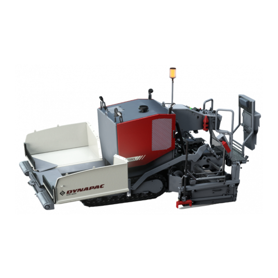
- Page 25 B Vehicle description App icati The DYNAPAC F1250CS paver finisher is a paver finisher with a caterpillar drive which is used for laying bituminous mixed material, roll-down or lean-mixed concrete and unbound mineral aggregates for foundations for paving.
- Page 26 Descripti f asse b ies a d fu cti Item Designation Material compartment (hopper) Truck push rollers Tube for sensor rod (direction indicator) holder Caterpillar drive Levelling cylinder for paving thickness Paving thickness indicator Crossbeam Travel drive of the caterpillar drive Conveyor Auger Screed...
- Page 27 Vehic e structi The paver finisher has a welded steel frame on which the individual components are mounted. The caterpillar drives are part of the frame structure; the suspension of the attached screed additionally helps to attain high paving precision. The continuously adjustable hydrostatic travel drive allows the speed of the paver fin- isher to be matched to all work conditions.
- Page 28 Hydrau ic syste The diesel engine drives the hydraulic pumps for all main paver finisher drives via the attached distribution gear and its auxiliary drive shafts. Trave drive The continuously adjustable travel drive pumps are connected to the travel drive engines by means of high pressure hydraulic hoses. These hydraulic motors drive the caterpillar chains via planetary gears that are mounted directly inside the drive units of the caterpillar chains.
- Page 29 eve i g s pe c syste The standard paver finisher is prepared electrically and hydraulically to fit an automatic levelling system. The levelling system monitors the paving thickness and corrects any deviations from the nominal level automatically. The system consists of optional combinations of: - Height controllers - Slope controller - Digital controllers...
- Page 30 Da ger WARNING Da ger f r pers s i the da ger Persons in the danger zone can suffer severe to fatal inju- ries from movements and functions of the vehicle! - Remaining in the vehicle's danger zone during operation is prohibited! - During operation, only the vehicle operator and the screed personnel are allowed on the vehicle or in...
- Page 31 Safety devices...
- Page 32 Item Designation Hopper transport safeguard Screed transport safeguard Main switch Travel drive safety switch Emergency stop button Horn Ignition key Lights Rotary beacon Screed warning light Covers, lateral flaps, coverings Located on both sides of the vehicle Safe operation is only possible when all operating and control elements are function- ing correctly and when all safety devices are in position.
- Page 33 Tech ica data sta dard c figurati Di e si s (a di e si 1605 1465 1380 1390 4140 4760 2675 1432 2818 3915...
- Page 34 Per issib e appr ach a g e max. 14° max. 12.8° B 10...
- Page 35 Weights F1250CS (all weights in t) Paver finisher without screed Approx. 5.71 Paver finisher with screed: Approx. 6.94 - V2400TV Approx. 6.94 - V2400TV-E With filled hopper approx. 5.0 additionally max. For the weights of the screed and the screed attachments, see the operating instruc- tions for the screed.
- Page 36 Trave drive tracti u it Drive Hydrostatic drive, continuously controllable Two separately driven caterpillar drives Drive unit with rubber grouser chains Turning capacity Turning on the spot Speed See above E gi e EU 3A Tier 3 Make/type Deutz TD 2.9 L4 Version 4-cylinder diesel engine Performance...
- Page 37 ateria c part e t (h pper) Volume Approx. 2.3 m = approx. 5.0 t Input height 570 mm 5 10 ateria tra sfer Type Simple conveyor belt Width 620 mm Conveyor operation Automatic by means of mechanical limit switches 5 11 ateria distributi Augers...
- Page 38 5 14 Radi re te c Transponder voltage 3.6V Transponder frequency range 2400- 2483.5Mhz Transmitter frequency band Transmitter frequency range 2400- 2483.5Mhz Number of transmitter channels Transmitter power consumption 30mA Receiver frequency range 2400- 2483.5Mhz Rechargeable battery voltage 3.6V Rechargeable battery capacity Battery charger 10-30V DC B 14...
- Page 39 Ide tificati p i ts CAUTION Da ger due t issi g r isu derst d vehic e sig s Missing or misunderstood vehicle signs pose a danger of injuries! - Never remove any warnings or information signs from the vehicle. - Damaged or lost warning or information signs must be replaced immediately.
- Page 40 B 16...
- Page 41 xxxxxxxxxxxxxxxxx B 17...
- Page 42 War i g sig s Pictogram Meaning War i g perati g i structi Danger due to improper operation. The machine personnel must have read and understood the safety, operating and maintenance instructions for the machine before the machine is put into operation! Failure to comply with the op- erating and warning instructions can cause severe to fatal injuries.
- Page 43 Pictogram Meaning War i g Spri g aded part! Performing work incorrectly can cause severe to fatal injuries. Always observe the maintenance instructions! Cauti Da ger fr i c rrect t wi g! Vehicle movements can cause severe to fatal injuries. The traction system brake must be released before towing.
- Page 44 I f r ati sig s Pictogram Meaning perati g I structi Position of the storage compartment. Diese fue Position of the filling point. - Diese fue su phur eve 15 pp Position of the filling point, specification. ifti g p i t Lifting the machine is only permitted at these lifting points! ai battery switch...
- Page 45 No. Pictogram Meaning E gi e i Position of the filling and control point. E gi e i drai age p i t Position of the drainage point. Gear i drai age p i t Position of the drainage point. Gearb x i Position of the filling and control point.
- Page 46 ar i g No. Pictogram Meaning CE, sound output level B 22...
- Page 47 I structive sy b s pr hibitive sy b s war i g sy b s No. Pictogram Meaning Wear ear protectors Warning on dangers posed by batteries! Do not spray the area or component with water! B 23...
- Page 48 Ide tificati abe f r the paver fi isher (41) Pos. Description Vehicle designation Designation type Year of construction Serial number (product identification number (PIN)) Operating weight, incl. all extension parts, in kg Maximum permitted total weight in kg Maximum permitted axle load kg - axle 1 Maximum permitted axle load kg - axle 2 Maximum permitted axle load kg - axle 3 Rated performance in kW...
- Page 49 Explanation of 17-digit PIN serial number >10002014JHG002076< - Manufacturer - Family/Model - Code letter - Serial number B 25...
- Page 50 E gi e type p ate The engine type plate (1) is affixed on top of the engine. The type plate states the engine type, serial number and engine data. Please state the engine number of the engine when ordering spare parts. See also operating instructions for the engine.
- Page 51 E sta dards ti u us s u d pressure eve The operator always must use ear protection. The emission value at the ear of the driver varies depending on the materials used for paving and may even rise above 85 dB(A). If no ear protectors are used, hearing can be impaired. The noise emission level of the paver finisher was measured under free-field condi- tions according to the EN 500-6 draft dated March 1997, and ISO 4872.
- Page 52 Vibrati acti g the e tire b dy When the vehicle is used properly, the weighted effective acceleration values at the driver’s seat of a = 0.5 m/s according to DIN EN 1032 are not exceeded. Vibrati s acti g ha ds a d ar s When the vehicle is used properly, the weighted effective acceleration values at the driver’s seat of a...
- Page 53 C 10 12 Tra sp rtati Safety regu ati s f r tra sp rtati Accidents can happen when the paver finisher and the screed are not properly pre- pared for transportation or when transportation is carried out improperly! Reduce both the paver finisher and the screed to their basic widths. Remove all pro- truding parts (such as the automatic levelling system, auger limit switches, side shields, etc.).
- Page 54 Directi g f the vehic e WARNING Da ger due t i c rrect directi g f the vehic e A banksman must be used when visibility is impaired on roads or transport roads and when loading the vehicle. Incorrectly implemented or misunderstood directions given by the banksman can cause severe to fatal injuries! The banksmen assigned for directing vehicles may only consist of personnel...
- Page 55 Tra sp rtati w bed trai ers WARNING Da ger due t vehic e adi g Loading or unloading the vehicle onto or from another vehi- cle poses a potential risk of accident. Vehicles can tip over on driving onto the low-bed trailer and cause severe to fatal injuries! - The transportation vehicle must always meet the requirements for transportation and be designed for this.
- Page 56 Preparati - Prepare the paver finisher for transportation (see chapter D). - Remove all overlaying or loose parts from finisher and screed (see also operating instructions for the screed) and store securely. These include: - Rotary beacon - Direction of travel indicator - All parts of the levelling system - Close open electrical connections with the related screw caps.
- Page 57 Operation Switch Close the hopper lids. Insert hopper transport safeguards. Lift the screed. Insert the transportation safeguards of the screed. Fully extend the levelling cylinder. Retract the screed parts until the screed matches the basic width of the paver finisher. C 10.12 5...
- Page 58 Securi g the The following instructions for securing the load on the low-bed trailer consist merely in examples of how to secure the load correctly. Always comply with the local regulations for securing the load and for correct use of load securing equipment.
- Page 59 Prepare the w bed trai er The floor of the loading space must always be undamaged, free of oil and mud, dry (residual moisture is permitted without accumulations of water) and swept clean! C 10.12 7...
- Page 60 Drivi g t the w bed trai er Make sure that there are no persons in the danger area during loading. - Use the work gear and low engine speeds to drive onto the low-bed trailer. C 10.12 8...
- Page 61 ashi g equip e t Use the load securing equipment, lashing straps and chains belonging to the vehicle. Additional shackles, eyebolts, edge guards and non-slip mats may be needed de- pending on the type of load securing equipment. Always comply with the stated values for permitted lashing force and load rating! Always tighten the lashing chains and straps hand-tight (100-150 daN).
- Page 62 ashi g equip e t tact surfaces swept c ea a d free f fr st ice a d s Lashing chain permissible lashing force LC 2,000 daN Lashing straps permissible lashing force LC 2,000 daN Non-slip mats C 10.12 10...
- Page 63 adi g Pay attention to load distribution during loading! In some vehicles, the kingpin load is too low so that the load has to be positioned fur- ther to the back of the vehicle (A). Always heed the details regarding load distribution stipulated for the vehicle together with the centre of gravity of the paver finisher (B).
- Page 64 Prepari g the vehic e After the vehicle has been positioned on the low-bed trailer, the following prepara- tions must be carried out: - Position the non-slip mats under the screed across the whole width of the vehicle (1) and lower the screed. - Switch off the paver finisher.
- Page 65 Securi g the Securi g i directi f trave Diagonal lashing secures the paver finisher at the front using the lashing points on the paver finisher and on the low-load trailer. The lashing equipment must be installed as shown. C 10.12 13...
- Page 66 ashi g a g e Contact surfaces swept clean and free of frost, ice and snow: The lashing angles should be: "ß" between 15° - 30° and "a" between 9° - 50°! Contact surfaces not swept clean and not free of frost, ice and snow: The lashing angles should be: "ß"...
- Page 67 Securi g pp site directi f trave Diagonal lashing secures the paver finisher at the front using the lashing points on the paver finisher and on the low-load trailer. The lashing equipment must be installed as shown. C 10.12 15...
- Page 68 ashi g a g e Contact surfaces swept clean and free of frost, ice and snow: The lashing angles should be: "ß" between 20° - 55° and "a" between 5° - 65°! Contact surfaces not swept clean and not free of frost, ice and snow: The lashing angles should be: "ß"...
- Page 69 After tra sp rtati - Remove the attachment devices. - Start engine. - Lift the screed to the transportation position. - Drive from the trailer at a low engine revs/speed. - Park the paver finisher in a secure spot, lower the screed and switch off the engine. - Remove the key and/or cover the operating panel with the protective hood and se- cure it.
- Page 70 Tra sp rtati Reduce the paver finisher and the screed to their basic widths; also remove any attached side shields. Preparati - Prepare the paver finisher for transportation (see chapter D). - Remove all overlaying or loose parts from finisher and screed (see also operating instructions for the screed).
- Page 71 Operation Switch Close the hopper lids. Insert hopper transport safeguards. Lift the screed. Insert the transportation safeguards of the screed. Fully extend the levelling cylinder. Retract the screed parts until the screed matches the basic width of the paver finisher. C 10.12 19...
- Page 72 Drivi g Operation Switch Set the fast/slow switch to "Hare" if necessary. Turn the preselector to "zero". Press the safety switch The safety switch must always be pressed when the drive lever is moved out of the neutral position. Otherwise the travel drive is blocked! Swivel the drive lever to maximum.
- Page 73 adi g by cra e WARNING Da ger fr suspe ded Crane and/or lifted vehicle can tip when lifted and cause injuries! - The vehicle may only be raised at the marked lifting points. - Heed the operating weight of the vehicle. - Do not enter the danger zone.
- Page 74 Example: Four lifting eyes (1, 2) are provided for loading the vehicle with a crane. Depending on the type of screed which is used, the paver finisher's centre of gravity, with the screed mounted, is located in area (3) of the vehicle. - Secure vehicle wherever it is parked up.
- Page 75 T wi g Heed all regulations and apply all safety measures applicable for towing heavy con- struction machines. The towing vehicle must be capable of securing the paver finisher, even on slopes. Use only approved tow bars! If necessary, remove any attachments and accessories from the paver finisher and the screed until the basic width has been attained.
- Page 76 Two high-pressure cartridges (6) are lo- cated on both of the travel drive pumps (5). The following activities must be carried out to activate the towing function: - Loosen lock nut (7) half a turn. - Screw in the bolt (8) until increased re- sistance occurs.
- Page 77 Safe y par i g the vehic e When the paver finisher is parked at a lo- cation accessible to the public, it must be secured in such a way that unauthorised persons or playing children cannot dam- age the vehicle. - Pull off the ignition key and the main switch (1) and take it with you –...
- Page 78 ifti g the vehic e with hydrau ic ifts ifti g p i ts The hydraulic lift must be rated for at least 8t. Always choose a horizontal surface with adequate load rating as installation surface for the hydraulic lift! Make sure that the hydraulic lift is securely and correctly positioned! The hydraulic lift is only intended to lift a load and not as a support.
- Page 79 Chocks or supporting beams positioned so that they cannot be shifted or tilted must be adequately dimensioned and be able to take the corresponding weight. There must not be anyone on the vehicle while it is being lifted. All raising and lowering work must be carried out uniformly with all hydraulic lifts in use! Always check and observe horizontal alignment of the load! Always carry out raising and lowering work with several people together, with an ad- ditional person monitoring progress!
- Page 80 C 10.12 28...
- Page 81 D 10 12 perati Safety regu ati Starting the engine, the travel drive, the conveyor, the auger, the screed or the lifting devices can cause injuries or even the death of persons. Make sure before starting any of these devices that no-one is working at, in or be- neath the paver finisher or within its danger area! - Do not start the engine or do not actuate any controls when this is expressly forbidden! Unless otherwise specified, the controls may only be actuated when the engine...
- Page 82 Da ger due t i pr per perati DANGER Improper operation of the vehicles can cause severe to fatal injuries! - The vehicle may only be used in the proper manner for its intended purpose. - The vehicle may only be operated by trained staff. - The vehicle operators must have made themselves famil- iar with the contents of the operating instructions.
- Page 83 tr s perati g pa e All detent switch functions that can pose a hazard when the diesel engine starts up (conveying function of auger and conveyor) prevent the engine from starting when set to "MANUAL". To be able to use the functions in the "MANUAL operating mode, they must be switched off and then to "MANUAL"...
- Page 84 D 10.12 4...
- Page 85 Item Designation Brief description Lights up instrument panel A/B when the parking light is Lights switched on Press in an emergency (danger to persons, impending colli- sion, etc.)! Pressing the emergency stop button switches off the en- gine, the drives and the steering system. Making way, lifting the screed or other actions are then no Emergency stop longer possible! Danger of accident!
- Page 86 D 10.12 6...
- Page 87 Item Designation Brief description For switching on the paver finisher functions and for continu- ously regulating the road speed – forward or reverse. Centre position: Engine in neutral; no travel drive; - To swivel the drive lever out, release by pulling the handle (16) up.
- Page 88 D 10.12 8...
- Page 89 Item Designation Brief description For setting the maximum speed that can be reached when the drive lever is at its stop. The scale roughly matches the speed in m/min (during paving). Travel drive preselector The vehicle speed cannot be reduced to "0" with the preselector.
- Page 90 D 10.12 10...
- Page 91 Item Designation Brief description Pushbutton function: - Upper switch position: Close left hopper lid. Open / close - Lower switch position: left hopper Open left hopper lid. On actuation, heed danger zones of moving parts of the vehicle! Pushbutton function: - Upper switch position: Close right hopper lid.
- Page 92 D 10.12 12...
- Page 93 Item Designation Brief description Pushbutton function: - Left switch position: Extend left half of screed. Retract / extend - Right switch position: left screed Retract left half of screed. On actuation, heed danger zones of moving parts of the vehicle! Pushbutton function: - Left switch position: Retract right half of screed.
- Page 94 D 10.12 14...
- Page 95 Item Designation Brief description Detent switch function: -Operating mode "AUTO": The conveying func- tion of the left half of the auger is switched on when the drive lever is swivelled out and is con- tinuously controlled via the material limit switches. Left auger - -Operating mode "OFF": The conveying func- Operating mode...
- Page 96 D 10.12 16...
- Page 97 Item Designation Brief description Pushbutton function: - Right switch position: The conveying direction of the left half of the auger can be reversed in order to slightly reverse paving Reversing switch material for example. Left auger The function can be triggered in all modes of the auger. On actuation, heed danger zones of moving parts of the vehicle! Pushbutton function:...
- Page 98 D 10.12 18...
- Page 99 Item Designation Brief description Joint, continual adjustment of the auger and conveyor speed. Transfer amount The transfer amount must be matched to the existing controller paving situation. Auger, conveyor Adjustment is possible during operation. D 10.12 19...
- Page 100 D 10.12 20...
- Page 101 Item Designation Brief description Detent switch function: -Operating mode "AUTO": The conveying func- tion of the conveyor is switched on when the drive lever is swivelled out and is switched off via the material limit switches. Conveyor -Operating mode "OFF": The conveying func- Operating mode tion of the conveyor is switched off.
- Page 102 D 10.12 22...
- Page 103 Item Designation Brief description Detent switch function: - Filling function for the paving process. The conveying functions set to "automatic" (conveyor and auger) are switched on. The engaged function is shown in the display of the ve- hicle as "activated". Fill vehicle for Once the set material height is reached at the limit paving process...
- Page 104 D 10.12 24...
- Page 105 Item Designation Brief description Pushbutton/detent switch function: - Upper switch position: Lift the screed. - Switch position, central: Screed stop (floating position OFF): Screed is hy- draulically blocked in position. - Lower switch position: Raise / lower Lower screed + floating position: Screed is lowered screed and released in the floating position when the drive le- Screed stop...
- Page 106 D 10.12 26...
- Page 107 Item Designation Brief description Detent switch function: -Operating mode "AUTO": The screed tamper is Tamper - switched on when the drive lever is swivelled out. Operating mode "AUTO" / -Operating mode "OFF": The screed tamper is "OFF" / switched off. "MANUAL"...
- Page 108 D 10.12 28...
- Page 109 Item Designation Brief description Detent switch function: -Operating mode "AUTO": Screed vibration is Vibration - switched on when the drive lever is swivelled out. Operating mode "AUTO" / -Operating mode "OFF": Screed vibration is "OFF" / switched off. "MANUAL" -Operating mode "MANUAL": Screed vibration is switched on constantly.
- Page 110 D 10.12 30...
- Page 111 Item Designation Brief description Detent switch function: -Operating mode "OFF": The automatic level- Levelling ling function is switched off. Operating mode "AUTO" / -Operating mode "AUTO": height adjustment is "OFF" carried out automatically via the connected grade control system. Pushbutton function: - Upper switch position: Retract left levelling cylinder.
- Page 112 D 10.12 32...
- Page 113 Item Designation Brief description Detent / pushbutton function: -Upper switch position: Preselection of the speed level - transportation speed (fast). -Switch position, central: Preselection of the speed level - operating speed (slow). -Lower switch position: Turning on the spot - The paver finisher turns on the spot (the cater- pillar chains run in opposite directions), when the steering potentiometer is turned.
- Page 114 D 10.12 34...
- Page 115 Item Designation Brief description Detent switch function: - Upper switch position: Separator fluid Spray system "ON" spray system ON / OFF (o) - Lower switch position: Spray system "OFF" Detent switch function: - Lower switch position: Vehicle control takes place on the paver finisher op- erator's platform - Upper switch position: Vehicle control takes place on the radio remote control.
- Page 116 D 10.12 36...
- Page 117 Item Designation Brief description Pushbutton function: - Upper switch position: Release Release travel drive for 2 seconds. travel drive The drive lever must be operated in this period of time, otherwise the travel drive is blocked. D 10.12 37...
- Page 118 D 10.12 38...
- Page 119 Item Designation Brief description Detent switch function: - Upper switch position: Screed heater system "ON“. - Lower switch position: Screed heater system "OFF". Heating ON/OFF The automatic temperature control of the screed heater system is carried out with activation. Gas heating (o): This opens the non-return valves for the gas supply to the burners and activates the electron- ic ignition system and the flame monitoring system D 10.12 39...
- Page 120 D 10.12 40...
- Page 121 Item Designation Brief description Input and display terminal for showing various vehicle param- eters, activation of functions, etc. Display To operate the display, see the corresponding part of this manual. D 10.12 41...
- Page 122 E ectric heati g e e e t (o) D 10.12 42...
- Page 123 Item Designation Brief description See the section "Insulation monitoring" in the screed op- Reset key erating instructions. for insulation monitoring The indicator lamp shows that the alternator is switched Indicator lamp Alternator on by the activated screed heating system. The indicator lamp is active as soon as the screed heat- Indicator lamp ing system is switched on by the automatic control sys- Heating...
- Page 124 Gas heati g e e e t (o) D 10.12 44...
- Page 125 Item Designation Brief description Malfunction display Left middle section malfunction display, red Malfunction display Left extendable part malfunction display, red Malfunction display Right middle section malfunction display, red Malfunction display Right extendable part malfunction display, red Via the temperature sensor and flame monitoring system, the electronics monitor gas heater operation.
- Page 126 te c Depending on the side of the machine (left/right), the function switches only control the corresponding function on the particular side of the machine. D 10.12 46...
- Page 127 Item Designation Brief description - For controlling paving-relevant paver and screed Left remote functions on the left side of the vehicle. control - For controlling paving-relevant paver and screed Right remote functions on the right side of the vehicle. control - For connecting the external levelling system to the left Socket of the vehicle.
- Page 128 D 10.12 48...
- Page 129 Item Designation Brief description Press in an emergency (danger to persons, impending colli- sion, etc.)! Pressing the emergency stop button switches off the en- gine, the drives and the steering system. Making way, lifting the screed or other actions are then no Emergency stop longer possible! Danger of accident! button...
- Page 130 D 10.12 50...
- Page 131 Item Designation Brief description Pushbutton function: - Switch position in the corresponding direction: Retract / extend extend or retract left / right screed half. left / right screed On actuation, heed danger zones of moving parts of the vehicle! D 10.12 51...
- Page 132 Radi re te c Da ger due t i pr per perati WARNING radi re te c Improper operation of the vehicles with the radio remote con- trol can cause severe to fatal injuries! - The vehicle may only be used in the stipulated manner for its intended purpose.
- Page 133 All other functions stored on the radio remote control, main operating panel or remote control can be carried out by all control units! A radio link must be established before beginning work for operation with the radio remove control. See the section "Establish radio link". D 10.12 53...
- Page 134 Safety switch (ti t se s r) The radio remote control is equipped with a tilt sensor as a safety measure! An acoustic warning signal is output at an angle of > 45° (all axles). Another 3 sec- onds later, the travel drive and the operating functions of the vehicle are switched off! The switch-off is signalled as an error message in the vehicle display and with an LED (111).
- Page 135 Safety switch ff with radi i terrupti As a safety measure, the travel drive is switched off when the radio link fails. The cause of the radio link failure can be too great a distance between the radio re- mote control and the paver finisher. An acoustic warning signal is output for 5 seconds prior to switch-off.
- Page 136 Estab ish radi D 10.12 56...
- Page 137 The drive engine need not be started to establish the radio link. - Insert the ignition key of the vehicle (14) in position "0" and turn it to Position "I" (Ignition On). - On the main operating panel, set the "Operating mode radio remote control/opera- tor's platform"...
- Page 138 Rechargeab e battery f radi re te c The rechargeable battery of the radio remote control is charged in an external battery charger (accessory). Charging time of rechargeable battery: approx. 1.5 hours. Operating time of the remote control with a battery charge: approx. 8 hours. Charge rechargeab e battery i exter a battery charger - Slide the lock (1) on the power supply unit forward and pull the plug (2) up-...
- Page 139 Cha ge i sert rechargeab e battery If the rechargeable battery is removed during an active radio link and with the vehicle running, the vehicle will be switched off! - Turn the On/Off switch (1) to Posi- tion "0" and pull it out. - Press in the rechargeable battery (2) toward the front and remove it down- ward out of the battery compartment.
- Page 140 e e e ts f radi re te c D 10.12 60...
- Page 141 Item Designation Brief description The radio remote control is switched on and off and the radio link to the vehicle is established with the key switch. - Turn the key switch Position "I" to switch on the radio remote control and establish the radio link. - Radio link established: short beep Key switch The LED indicator lamp (110) signals the established...
- Page 142 D 10.12 62...
- Page 143 Item Designation Brief description The steering wheel movement is transferred electrohydraulically. Steering For precise adjustments (position "0" = straight-ahead), potentiometer see the straight-ahead travel synchronisation (main operating panel). For switching on the paver finisher functions and for continu- ously regulating the road speed – forward or reverse. Centre position: Engine in neutral;...
- Page 144 D 10.12 64...
- Page 145 Item Designation Brief description Press in an emergency (danger to persons, impending colli- sion, etc.)! The engine, drives and steering system are switched off when the emergency stop button is pressed. Making way, lifting the screed or other actions are then no Emergency stop longer possible! Danger of accidents! button...
- Page 146 D 10.12 66...
- Page 147 Item Designation Brief description Confirms the switched-on radio remote control and indi- cates the charging state of the rechargeable battery: LED indicator lamp - LED green: Radio remote control connected, "Radio remote battery charged. control ON"/ - LED red-green: Radio remote control connected, "Battery voltage battery weak.
- Page 148 D 10.12 68...
- Page 149 Item Designation Brief description Pushbutton function: - To lock all functions relevant to paving. Despite "Auto" settings in the individual functions, these are not activated when the drive lever is swivelled out or when the drive lever is swivelled out and stopped. Main function - The tamper, vibration and levelling functions are not switch...
- Page 150 D 10.12 70...
- Page 151 Item Designation Brief description Pushbutton function: - Upper switch position: Operating mode "MANUAL": The conveying function of the left half of the auger is connected with the full conveying rate; no material control is carried out via the limit switches. The "Auto function"...
- Page 152 D 10.12 72...
- Page 153 Item Designation Brief description Pushbutton function: - Upper switch position: Operating mode "MANUAL": The conveying function of the right half of the auger is connected with the full conveying rate; no material control is carried out via the limit switches. The "Auto function"...
- Page 154 D 10.12 74...
- Page 155 Item Designation Brief description Pushbutton function: - Upper switch position: Operating mode "MANUAL": The conveying function of the conveyor is connected with the full conveying rate; no material control is carried out via the limit switches. The "Auto function" connected on the main operating panel is overridden.
- Page 156 D 10.12 76...
- Page 157 Item Designation Brief description Pushbutton function: - Filling function for the paving process. The conveying functions set to "automatic" (conveyor and auger) are connected without deflecting the drive lever. Fill vehicle for paving process Once the set material height is reached at the limit switches, the conveying functions are switched off.
- Page 158 D 10.12 78...
- Page 159 Item Designation Brief description Pushbutton function: - Upper switch position: Retract left levelling cylinder. - Lower switch position: Extend left levelling cylinder. Retract / extend left levelling The "AUTO" and "OFF" operating modes switched on cylinder the main operating panel or remote control are overrid- den when operated.
- Page 160 D 10.12 80...
- Page 161 Item Designation Brief description Pushbutton function: - Left switch position: Extend left half of screed. Retract / extend - Right switch position: left screed Retract left half of screed. On actuation, heed danger zones of moving parts of the vehicle! Pushbutton function: - Left switch position: Retract right half of screed.
- Page 162 a fu cti s i radi re te c Malfunction Possible Cause Remedy - Have checked by and, if necessary, - Antenna defective renewed by an expert - Receiver is not con- - Check plug connector from receiver nected or is connected to vehicle incorrectly - Receiver and radio...
- Page 163 D 10.12 83...
- Page 164 D 10.12 84...
- Page 165 D 24 12 perati g the disp ay D 24.12 1...
- Page 166 perati f the i put a d disp ay ter i a Butt ay ut the disp ay - (A) Function buttons: - To select the menus assigned in the display area (A1). For orientation, the corresponding symbol shows an opened menu in the status line (B). To confirm an active/opened menu, the colour of the cor- responding symbol changes from pale to dark grey! - (B) Display area for status, warning and error messages:...
- Page 167 The colour of the symbol indicates whether it is a status, warning or error message. Colour code Explanation RED - error message - Reports a serious fault that must be checked and rec- tified immediately. YELLOW - warning message - Reports a current condition that needs to be observed or rectified at short notice to ensure correct working.
- Page 168 Disp ay f activated fu cti Pressing the corresponding function button activates or deactivates the functions that can be switched on and off. The function is activated when the corresponding symbol (1) appears blue. Some functions switched on with the operating panel are shown for confirmation in the display area (A).
- Page 169 e u perati pr cedure f r ad usti g para eters Example: Adjusting the screed temperature - The "Home" menu is open in the display. - Press button (A) to open the "screed heater" menu. - Press the plus / minus button (B) / (C) to activate the selected parameter to be adjusted. A blue frame appears around the temperature parameter.
- Page 170 Se ecti g a d cha gi g a ad ust e t para eter i a - Press button (A) to activate the selected parameter to be adjusted. A blue frame appears in the area which is activated for the adjustment. - Press button (A) until the blue frame is around the required adjustment parameter - Press button (B) to activate the selected parameter to be adjusted.
- Page 171 e u structure e u f the "H e" disp ays Displays: - (1) Speed: - Paving (tortoise) - Driving (hare) - (2) Fuel gauge - (3) Actual temperature of the screen heater (°C) / (°F) The display shows the average temperature of all screed sections. - (4) Actual diesel engine speed (n/min) - (5) Time of day (hh:mm) (AM/PM) D 24.12 7...
- Page 172 "H e" fu cti s "Quic Setti gs" Menu for directly activating various functions. Pressing the corresponding function button activates or deactivates the functions. The function is activated when the corresponding symbol appears blue. - (1) "Conveyor switch-off" function With the function activated, the conveyor switch-off is only carried out with when both conveyor switches are operated simultaneously.
- Page 173 "Particu ate Fi ter Rege erati " e u (o) E gi e easured va ue disp ay Menu for triggering requested active filter regeneration, for disabling automatic filter regeneration and for checking various measured values of the engine. The menu for filter regeneration is only displayed for vehicles with corresponding ex- haust gas aftertreatment.
- Page 174 Da ger fr particu ate fi ter rege erati DANGER Improper particulate filter regeneration can cause severe to fatal injuries! - Keep the outlet of the exhaust pipe out of the reach of peo- ple and of objects that can burn, melt or explode! - There may not be any people or objects within a radius of 0.6 m of the exhaust outlet! - There may not be any objects or substances that can burn,...
- Page 175 Drive e gi e easured va ue disp ay The menu for filter regeneration is only displayed for vehicles with corresponding ex- haust gas aftertreatment. - (3) Engine coolant temperature (°C) / (°F) - (4) Engine operating hours (h) - (5) On-board voltage (V) Call up the following menus: - (6) "Home"...
- Page 176 "Screed Heater" ad ust e t a d disp ay Menu for adjusting the nominal screed heater temperature and for checking the actu- al temperatures. - (1) Nominal screed heater temperature display and adjustment parameters. - (2) Average actual temperature of all screed sections (°C) / (°F) Direct adjustment of the nominal temperature by pressing the plus / minus buttons (3) / (4).
- Page 177 "Err r ry" Menu for retrieving existing error messages. - (1) Number of error messages with travel drive stop. - Open detailed display "Error Messages With Travel Drive Stop": (1.1). - (2) Number of vehicle warning messages. - Open detailed display "Vehicle Warning Messages": (2.1). - (3) Number of engine error messages.
- Page 178 Detai ed disp ay "Err r essages With Trave Drive St p" Display of existing error messages in a table. - (1) Error code. - (2) Error description. - (3) Parameters (see Bodas error list). If present, the following page of the list is shown after a few seconds in each case. Call up the following menus: - (4) "Vehicle Warning Messages"...
- Page 179 Detai ed disp ay "Vehic e War i g essages" Display of existing error messages in a table. - (1) Error code. - (2) Error description. - (3) Parameters (see Bodas error list). If present, the following page of the list is shown after a few seconds in each case. Call up the following menus: - (4) "Error Messages With Travel Drive Stop"...
- Page 180 Detai ed disp ay "E gi e Err r essages" Display of existing error messages in a table. - (1) SPN code. - (2) FMI code. - (3) OC error frequency. All error messages can be identified in the section "Drive engine error codes". If present, the following page of the list is shown after a few seconds in each case.
- Page 181 "I f " Menu for calling up various vehicle information and sub-menus for various settings. Display of the following information: - (1) Software version of the vehicle - (2) Software version of the display If consultation with Technical Support is required for your vehicle, always specify the software version! Call up the following menus: - (4) "Error Messages With Travel Drive Stop"...
- Page 182 "Disp ay" set up Menu for setting up basic display settings. - "Time" display and adjustment parameters - (1.1) h/h : min/min - (1.2) 24hrs / PM/AM - (2) Selection "System Language" - English / German - (3) Selection "Units of measurement" - Metric / Imperial (US) - Monitor brightness display and adjustment parameters - (4.1): Daytime light (%)
- Page 183 Ter i a err r essages Status war i g a d err r essages sy b s Command Symbol in the display Driving release (for 2 seconds), display only at standstill Particulate filter indicator lamp. Particulate filter regeneration is necessary. - Indicator lamp on permanently: Urgent mainte- nance, level I.
- Page 184 Command Symbol in the display Indicator lamp automatic particulate filter re- generation - deactivated Particulate filter regeneration is deactivated. Automatic regeneration should only be deacti- vated if the operating status of the paver finish- er does not permit any automatic function. Warning - high exhaust gas temperature! (HEST) The indicator lamp indicates a high exhaust...
- Page 185 Command Symbol in the display Indicator lamp fuel reserve The fuel is down to the reserve level in the tank. Approx. 10% remains Urgent need to refuel! Pre-heating indicator (yellow) Pre-heating is started with the ignition starter by switching the ignition on. (ignition key in position 1).
- Page 186 Command Symbol in the display - Error message "Serious error" There is a serious error in the engine. Switch off the drive engine immediately! Error details can be viewed in the "Error Memory" display menu. Lights up for a few seconds once the ignition has been switched on for checking purposes.
- Page 187 Command Symbol in the display Engine stop: Display for all error messages with machine stop. Travel drive blocked - release switch not operated. Engine oil pressure The oil pressure is insufficient. Switch off the engine immediately! For other possible errors, see engine's oper- ating instructions.
- Page 188 Drive e gi e err r c des If a fault is detected on the engine, this is shown by the corresponding indication (1) in the display. D 24.12 24...
- Page 189 The error message that can be viewed in the corresponding menu contains several numerical codes, which clearly define the fault after decoding. If present, the following page of the list is shown after a few seconds in each case. It may be possible to continue operating the vehicle, depending on the severity of the error.
- Page 190 Example: D 24.12 26...
- Page 191 Explanation: Warning light and display signal a serious fault on the drive engine with automatic or necessary engine shut-down. Display: SPN: FMI: Cause: Cable break on sensor for rail pressure. Effect: Engine shut-down. Freque cy: Fault occurs for the 1st time. Notify customer service of the error number displayed on your paver finisher;...
- Page 192 e u structure f the setti g a d disp ay e us The following illustration shows the menu structure and serves to simplify operation and the procedure in the case of various settings and displays. D 24.12 28...
- Page 193 D 30 12 de f perati e e e ts the paver fi isher e e e ts the perat r's c stati WARNING Da ger f fa i g fr the vehic e Entering and leaving the vehicle and the driver's seat dur- ing operation poses a risk of falling from the vehicle, which can cause severe to fatal injuries! - The operator must be at the intended driver's seat...
- Page 194 p atf r The control platform is designed for op- erating standing up. - After work has been completed, place the vandalism protection facility (1) on the operating panel and secure with the corresponding lock. - The vandalism protection facility can be kept in bracket (2) during op- eration.
- Page 195 p atf r tra sp rtati p siti The control platform can be folded up to reduce the transportation length. - Unscrew the stop screws (1) and re- move the handrail (2). - Unscrew the detent pin (3) on the un- derside of the running board.
- Page 196 Da ger fr da aged r issi g WARNING perati g i structi Failure to comply with the operating instructions can cause severe to fatal injuries! - Familiarise yourself with the contents of the operating instructions. - Always keep the operating instructions in the intended place on the vehicle.
- Page 197 Fuse b x The terminal box, which contains all fus- es and relays, etc. is located beneath the operating panel. An assignment plan for fuses and relays can be found in chapter F8. D 30.12 5...
- Page 198 Batteries The batteries (1) of the 24 V system are located under the operating panel of the vehicle. For the specifications, refer to chapter B, "Technical data". For maintenance, see chapter "F". External starting only according to the in- structions (see section "Starting the paver finisher, external starting (starting aid)") ai battery switch The main battery switch separates the...
- Page 199 H pper tra sp rt safeguard Before parking or transporting the paver finisher, the hopper lids must be swung upwards and the transport safeguards for the hopper must be inserted. - Insert snap hook (A) in the corre- sponding shackle of the opposite hop- per lid.
- Page 200 Pavi g thic ess i dicat r at b tt Two scales (A), on which the currently set paving thickness can be read off, are located on the left and right sides of the vehicle. - Pointer (B) shows the paving thickness. In normal paving situations, the same paving thickness should be set on both sides of the vehicle!
- Page 201 Head ight f r auger c part e t (o) Two swivelling working lights (1) are provided to illuminate the auger compartment. They are engaged together with the working lights. ED w r i g ight (o) There are two LED spotlights (2) at the front and rear of the vehicle.
- Page 202 Auger height ad ust e t ratchet (o) For mechanical adjustment of the auger height - Set the ratchet direction lever (1) to the clockwise or anti-clockwise direction. Turning anti-clockwise lowers the au- ger, turning clockwise lifts the auger. - Actuate the ratchet lever (2) - Set the desired height by alternatingly actuating the left and right ratchets.
- Page 203 Se s r r d se s r r d exte si The sensor rod acts as an orientation aid for the vehicle driver during paving. Along the defined paving route, the vehicle driver can use the sensor rod to follow a tensioned reference wire or another marking.
- Page 204 - After releasing the wing nuts (4), the end section of the sensor rod (5) can be set to the desired length; the angle can additionally be changed by swivelling on the joint (6). The chain (7) can be used as a guide. Tighten all assembly parts properly after setting up! D 30.12 12...
- Page 205 a ua separat r f uid spray (o) Used to spray the parts coming into contact with asphalt with a separator emulsion. Only use approved separator emulsion in the spray (1)! - Build up pressure by actuating the pump lever (2). - The pressure is indicated on the ma- nometer (3).
- Page 206 Separat r f uid sprayi g syste Used to spray the parts coming into contact with asphalt with a separator emulsion. Only switch on the spraying system when the diesel engine is running; other- wise, the battery will be discharged. Switch off after use.
- Page 207 vey r i it switches The conveyor is switched "ON" and "OFF" using the paddles (1) and (2). - To set the deactivation point: - Loosen the screw (3) and move the paddle (4) until the required switch- ing point is reached. Retighten screw (3) properly.
- Page 208 Auger i it switches The augers are controlled by sensors. Mounting the sensors: Fasten the sensors to the side shield (1 sensor for each auger) in the provided clamp bracket (1) on the holding tube (2). Always mount the sensors (3) to ensure that they are not damaged on extending and retracting the screed.
- Page 209 24 v t s c ets (o) There is one socket (1) on each side of the operating panel console. Additional working lights can be con- nected here, for example. - 24V socket Voltage is present when the main switch is switched on.
- Page 210 Fire exti guisher (o) The paver finisher personnel must be fa- miliarised with operation of the fire extin- guisher (2). Observe the inspection interval for the fire extinguisher! First aid it (o) Any dressings that have been used must be replaced immediately! Heed the expiry date of the first-aid kit! D 30.12 18...
- Page 211 R tary beac The function of the rotary beacon must be checked daily before starting work. - Place the rotary beacon onto the plug- in contact and secure with a clamping bolt (1). - Extend the rotary beacon with tube (2) to the desired height and secure with the clamping bolt (3).
- Page 212 D 30.12 20...
- Page 213 D 40 12 de f perati Prepari g f r perati Required devices a d aids To avoid delays on site, check before starting work whether or not the following de- vices and aids are present: - Wheel loader for transporting heavy extension parts - Diesel fuel - Engine oil and hydraulic oil, lubricants - Separator fluids (emulsion) and manual injector...
- Page 214 CAUTION Da ger due t restricted visi Restricted vision poses a risk of injury! - Before starting work, arrange the intended driver's seat to ensure adequate vision. - Signalmen must be used when vision is restricted, also to the sides and when reversing. - Only reliable persons may be used as signalmen who must have been received instructions about their task before taking up their activity.
- Page 215 Bef re starti g w r (in the morning or when starting paving) - Heed the safety instructions. - Check the personal protective equipment. - Take an inspection walk around the paver finisher and check for leaks and damages. - Install parts removed for transportation or for the night. - When screed is operated with the optional gas heating system, open the closing valves and the main shut-off valve.
- Page 216 Check! How? When the screed is lifted, it must be Screed transport safeguard possible to push out both retaining pins and the crossbeams. When the hopper is closed, it must be Hopper transport safeguard possible to insert the safety chain between the two hopper lids.
- Page 217 D 40.12 5...
- Page 218 Starti g the paver fi isher Bef re starti g the paver fi isher Before starting the diesel engine and beginning operation, the following steps must be performed: - Daily maintenance of the paver finisher (see chapter F). Check the operating hour counter to determine whether or not additional mainte- nance work (e.g.
- Page 219 D 40.12 7...
- Page 220 Exter a starti g (starti g aid) The engine can be started with the help of an external power source if the batteries are empty and the starter no longer turns. Suitable power sources are: - Other vehicles with a 24V system - Additional 24V battery - Start device that is suitable for external starting (24 V/90 A).
- Page 221 - Turn ignition key (3) to position 1 and wait for the preheat check (8) to go off. - Press the starting button (9) to start the engine. Do not let the starter run permanently for more than 20 seconds, then allow for a break of one minute! If the engine does not start and the Error message (6) indicator lamp flashes, then the electronic engine control system has activated the start inhibit.
- Page 222 D 40.12 10...
- Page 223 After starti g Let the paver finisher warm up for approx. 5 minutes if the engine is cold. bserve i dicat r a ps The following indicator lamps must be observed under all circumstances: For other possible errors, see engine's operating instructions. Battery charge i dicat r (1) Must go out after starting.
- Page 224 D 40.12 12...
- Page 225 Preparati f r tra sp rtati - Use switch (1) to close the hopper. - Insert hopper transport safeguards. - Lift the screed completely using switch (2), insert screed transport safeguard. - Turn the travel drive preselector (3) to zero. - Fully extend the levelling cylinders with the switch (4).
- Page 226 D 40.12 14...
- Page 227 Drivi g a d st ppi g the paver fi isher - Set the travel drive to the desired speed level, fast/slow (1). - Upper switch position: transport speed (hare) - Switch position, central: operating speed (tortoise) - Turn the travel drive preselector (2) to medium speed. - Press the safety switch (3).
- Page 228 Preparati s f r pavi g Separat r f uid Spray the parts coming into contact with asphalt (hopper, screed, auger, push roller) with a separator fluid. Do not use diesel fuel as it dissolves the bitumen (prohibited in Germany!). Screed heater Switch on the screed heater approx.
- Page 229 Directi ar s To ensure straight paving, a direction mark must be present or established (road edge, chalk lines or similar). - Pull direction indicator of the bumper (arrow) and adjust it accordingly. D 40.12 17...
- Page 230 D 40.12 18...
- Page 231 adi g c veyi g ateria - Use switch (1) to open the hopper. Instruct the truck driver to dump the material. - Set the switches for the auger (2) and the conveyor (3) to "AUTO". The conveying function starts by deflecting the drive lever. Check that the material is transferred properly.
- Page 232 D 40.12 20...
- Page 233 Starti g f r pavi g Set the switches, levers and controls listed below to the specified positions when the screed has reached its operating temperature and a sufficient amount of material lies in front of the screed Item Switch Position Drive lever Centre position...
- Page 234 Chec s duri g pavi g The following points must be constantly observed during paving: Paver fu cti - Screed heater - Tamper and vibration - Engine oil and hydraulic oil temperature - The screed parts must be retracted and extended in time when obstacles are in the way - Uniform material transport and distribution or supply to the screed;...
- Page 235 D 40.12 23...
- Page 236 I terrupti g ter i ati g perati Duri g brea s i pavi g (e.g. delay due to material trucks) - Determine the approximate duration. - When cooling down of the material below the minimum paving temperature must be expected, run the paver finisher empty and create an edge like the end of a layer.
- Page 237 D 40.12 25...
- Page 238 Whe w r is fi ished - Run the paver finisher empty and stop it. - Move the drive lever (1) to the central position, set preselector (2) to "0" and set the speed adjuster (3) to minimum. - Switch the auger (4), conveyor (5), tamper (6), vibration (7) and levelling (8) func- tions to "OFF".
- Page 239 Problems during paving Problem Cause - change in the material temperature, demixing - wrong material composition - incorrect operation of the roller - incorrectly prepared foundation - long standstill times between loads - grade control reference line is not suitable - grade control jumps to the reference line - grade control toggles between up and down Wavy surface...
- Page 240 Problem Cause - material temperature Cracks in the layer - cold screed (centre strip) - bottom plates are worn or warped - wrong crowning - material temperature - screed extendable parts are incorrectly installed Cracks in the layer - limit switch is not correctly set (outer strip) - cold screed - bottom plates are worn or warped...
- Page 241 Malfunctions on the paver finisher or screed Malfunction Cause Remedy See operating instructions for At the diesel engine Various the engine See "External starting" Batteries empty Diesel engine (start assistance) does not start Various see "Towing" Tamper is obstructed Properly heat the screed by cold bitumen Hydraulic oil level in Top up oil...
- Page 242 Malfunction Cause Remedy Engine speed is too low Increase the speed Hydraulic oil level is too low Top up oil Leak in the suction line Tighten the connections Flow rate regulator Replace Hopper cannot be defective swung open Leaking seals of the Replace hydraulic cylinder Control valve is defective...
- Page 243 Malfunction Cause Remedy Control valve is defective Replace Hoppers lowers Leaking hydraulic cylinder inadvertently Replace sleeves Oil pressure too low Increase the oil pressure Screed cannot Leaking seal Replace be lifted Check fuse and cables; Power supply is interrupted replace if necessary Switch on the remote con- Set the switch to "Manual"...
- Page 244 Malfunction Cause Remedy Replace (fuse strip on the oper- Travel drive fuse defective ating panel) Check potentiometer, cables, Power supply is interrupted connectors; replace if necessary Travel drive monitoring Replace (type-specific) defective Traction does Electro-hydraulic servo unit Replace the servo unit not work of the pump defective Check and adjust if necessary...
- Page 245 E 10.12 Set-up and modification Specia safety i structi Danger to personnel by inadvertent starting of the engine, travel drive, conveyor, au- ger, screed or screed lifting devices. Unless otherwise specified, work may only be performed when the engine is at a standstill! - To protect the paver finisher against inadvertent starting: Move drive lever into centre position and turn preselector controller to zero, remove ignition key and battery main switch.
- Page 246 DANGER Da ger due t cha ges at the vehic e Structural chances to the vehicle make the operating licence null and void and can cause severe to fatal injuries! - Only use original spare parts and approved accessories. - After maintenance and repair work, ensure that any dis- mantled protective and safety devices are all completely fitted again.
- Page 247 Distributi auger Height ad ust e t Depending on the material, the height of the auger (1) – measured from its lower edge – should be at least 50 mm (2 inches) above the height of the material layer. Example: Paving thickness 10 cm Adjustment: 15 cm from the ground An incorrect height setting can result in the following problems during paving: - Auger too high:...
- Page 248 Auger width exte si ateria shaft with pr tective c ver ( pti a equip e t) To fit auger extensions, an additional auger segment (1) is fitted to the auger shaft. Assembly: - Remove outermost screw connection (2) from the basic auger. - Remove plug (3).
- Page 249 Material shaft, protective cover Suspend the material shaft (4) in the provided bracket on the basic unit and secure with the rod (5) and the corresponding splint pin. For larger paving widths: - Remove original shaft (4) - Fit extension shaft (6) - Secure original shaft (4) to extension shaft (6).
- Page 250 Push r er cr ssbar ad ustab e For adaptation to various truck design types, the push roller crossbar (1) can be shift- ed to two positions. The adjustment travel is 60 mm. - Hopper without front hopper flap: Open hopper halves and remove cover plate (2). - Hopper with front flap: Close hopper halves and remove cover (3).
- Page 251 ecti g the aut atic eve i g syste The paver finisher has two control circuits for levelling. One for the right side of the vehicle and one for the left side. The automatic levelling system can be suspended in the opened vandalism protec- tion facility in guide (1).
- Page 252 ecti g the s pe c height c The slope controller (3) and height con- troller (4) are connected to either the left or right automatic levelling system. Connect the coiled cables of the control- lers with the corresponding sockets (5) of the automatic levelling system.
- Page 253 i it switch I sta auger i it switches ( eft a d right) The auger's ultrasonic limit switch is mounted on both sides on the side board's handrail. - Position the sensor bracket (1) on the bracket at the side board of the screen, align and tighten with a wing bolt (2).
- Page 254 E 10.12 10...
- Page 255 F 10 ai te a ce tes regardi g safety DANGER Da ger due t cha ges at the vehic e Structural chances to the vehicle make the operating licence null and void and can cause severe to fatal injuries! - Only use original spare parts and approved accessories.
- Page 256 CAUTION H t surfaces! Surfaces including those behind covering parts, together with combustion fuels from the engine or screed heater can be very hot and cause injuries! - Wear your personal safety gear. - Do not touch hot parts of the vehicle. - Only perform maintenance and repair work after the vehicle has cooled down.
- Page 257 F 2 12 ai te a ce verview ai te a ce verview 8.12 11.12 5.12 6.12 3.12 4.12 7.12 F 2.12 1...
- Page 258 ai te a ce ecessary after perati g h urs Asse b y Chapter Conveyor F3.12 Auger F4.12 Engine F5.12 q q q q q q q q q q Hydraulic system F6.12 q q q q q q Drive units F7.12 Electrical system F8.12...
- Page 259 F 3 12 ai te a ce c vey r ai te a ce c vey r F 3.12 1...
- Page 260 Da ger f bei g pu ed i by r tati g r c veyi g WARNING vehic e parts Rotating or conveying vehicle parts can cause severe to fatal injuries! - Do not enter the danger zone. - Do not reach into rotating or conveying parts. - Only wear close-fitting clothing.
- Page 261 ai te a ce i terva s I terva ai te a ce p i t - Conveyor chain - Check tension - Conveyor chain - Adjust tension - Conveyor chain - Replace chain - Replace conveyor / conveyor drive - wear parts Maintenance Maintenance during the running-in period F 3.12 3...
- Page 262 ai te a ce p i ts Chai te si vey r (1) Chec chai te si To check and adjust the chain tension, the paver finisher must be located over a pit, on ramps or on a platform. The underside of the first crossmember (A) of the vehicle frame serves as a reference.
- Page 263 Ad ust e t f chai te si The adjusting screws (B) are located at the front of the vehicle on the cross- beam. - Dismantle the locking plates (C) of the adjusting screws. - Adjust the chain tension using the adjusting screw (B).
- Page 264 Chec rep ace chai The conveyor chain must be replaced at the latest when: - the conveyor webs (A) are worn or - the chain has lengthened to such an extent that it can no longer be retightened. Chain links must not be removed to shorten the chain! Incorrectly dividing the chains would lead to destruction of the drive wheels!
- Page 265 Rep ace c vey r vey r drive wear parts (2) Check the following wear parts in the material tunnel and replace if necessary: - Drive chain cover (A) - Bottom plate (B): - Wear plates (C): These must be replaced if the system is no longer sealed or there are holes in the parts.
- Page 266 F 3.12 8...
- Page 267 F 4 12 ai te a ce auger asse b y ai te a ce auger asse b y F 4.12 1...
- Page 268 Da ger f bei g pu ed i by r tati g r c veyi g WARNING vehic e parts Rotating or conveying vehicle parts can cause severe to fatal injuries! - Do not enter the danger zone. - Do not reach into rotating or conveying parts. - Only wear close-fitting clothing.
- Page 269 ai te a ce i terva s I terva ai te a ce p i t Auger drive chains - Check tension Auger drive chains - Adjust tension Auger drive chains - Replace chains and chain sprockets Auger box - Check grease fill Auger box - Top up grease...
- Page 270 ai te a ce p i ts Auger drive chai s (1) To chec the chai te si - Manually turn both augers to the right and left. In this case, movement clear- ance (C) at the augers' outer circumference should be 3-4 mm. Risk of injury due to sharp-edged parts! To re te si the chains...
- Page 271 Chec rep ace chai The drive chains (A) must be replaced at the latest when: - The sprockets (B) on the auger shaft or drive are worn. - The chains (A) have lengthened to such an extent that they can no longer be retightened.
- Page 272 Auger b x (2) Chec grease fi To chec the grease fill: - Remove side cover (A) No reduction in the quality and quantity of the grease fill is normally expected. However, the grease fill must always be replaced if there is a considerable change colour lumps...
- Page 273 Sea s a d sea i g ri gs (3) After reaching operating temperature, check the gearbox for leaks. In case of visible leaks, e.g. between the flange surfaces (A) of the drive, auger shaft (B) or at the side cover (C), re- placement of the seals and sealing rings is necessary.
- Page 274 Auger seg e ts (4) If the surface of the auger blade (A) be- comes sharp-edged, the diameter of the auger is reduced and the blades (B) have to be replaced. Remove the bolts (C), washers (D), nuts (E) and auger blade (B) Risk of injury due to sharp-edged parts! Auger blades must be installed play-free;...
- Page 275 F 5 12 ai te a ce e gi e asse b y ai te a ce e gi e asse b y As well as this maintenance manual, always also pay close attention to the mainte- nance manual provided by the engine manufacturer. All maintenance work and serv- ice intervals itemised here are binding in nature.
- Page 276 Da ger f bei g pu ed i by r tati g r c veyi g WARNING vehic e parts Rotating or conveying vehicle parts can cause severe to fatal injuries! - Do not enter the danger zone. - Do not reach into rotating or conveying parts. - Only wear close-fitting clothing.
- Page 277 ai te a ce i terva s I terva ai te a ce p i t - Fuel tank Check filling level - Fuel tank Refill with fuel - Fuel tank Clean the tank and system - Engine lube oil system Check oil level - Engine lube oil system Top up oil...
- Page 278 I terva ai te a ce p i t - Engine air filter Check air filter - Engine air filter Empty dust collector - Engine air filter Exchange air filter insert - Engine cooling system Check radiator fins - Engine cooling system Clean radiator fins - Engine cooling system Check level of the coolant...
- Page 279 I terva ai te a ce p i t - Engine drive belt Check drive belt - Engine drive belt Tighten drive belt - Engine drive belt Replace drive belt Maintenance Maintenance during the running-in period F 5.12 5...
- Page 280 ai te a ce p i ts E gi e fue ta - Check the fi i g eve on the gauge on the operating panel. Fill the fuel tank each time before start- ing work so that the fuel system cannot "run dry"...
- Page 281 E gi e ube i syste Chec i eve In case of correct oil level, the oil is be- tween the two notches of the dipstick (A). Only check the oil level when the finisher is in a horizontal position! The dipstick is located at the front end of the engine.
- Page 282 i cha ge The oil should be changed when at operating temperature. - Place the end of the oil drain port hose (C) in the collection container. - Remove the screw cap with a wrench and allow the oil to drain completely. - Replace the screw cap and tighten properly.
- Page 283 E gi e fue syste The fuel filter system consists of two filters: - Prefilter (A) with water separator - Main filter (B) Prefi ter drai i g f water Drain the collecting vessel at regular in- tervals, or in response to an error mes- sage from the engine control unit.
- Page 284 Cha gi g the prefi ter - Put a suitable drip pan underneath. - Disconnect the electrical connection/cable connection. - Loosen drain plug (C) and drain off liquid. - Untighten the filter cartridge (A) using a pair of oil filter tongs or oil filter strap and unscrew it.
- Page 285 E gi e air fi ter (4) E pty dust c ect r - Empty the dust removal valve (B) on the air cleaner housing (A) by pressing the discharge port in the direction of the arrow. - Remove any baked on dust by press- ing together the upper valve section.
- Page 286 E gi e c i g syste Chec i g t ppi g up c The cooling water level must be checked when the system is cold. Make sure that sufficient anti-freeze and anti-corrosion agent is available (-25°C). When hot, the system is under pressure. When it is opened, there is danger of scalding! - The fluid level must be up to the centre...
- Page 287 Cha ge c When hot, the system is under pressure. When it is opened, there is danger of scalding! Use only approved coolants! Observe the instructions in the chapter entitled "Operating substances"! - Remove the drain screw (A) on the radiator and coolant drain completely.
- Page 288 Chec i g a d c ea i g the radiat r fi s - If necessary, remove leaves, dust or sand from the radiator. Observe engine's operating instructions! Chec c a t c ce trati - Check the concentration using a suitable tester (hydrometer). - Adjust the concentration if necessary.
- Page 289 E gi e drive be t (6) Chec drive be t - Check the drive belt for damage. Small transverse cracks in the belt are acceptable. In the event of longitudinal cracks which intersect with transverse cracks and damaged material surfaces, belt re- placement is necessary.
- Page 290 F 5.12 16...
- Page 291 F 6 12 ai te a ce hydrau ic syste ai te a ce hydrau ic syste F 6.12 1...
- Page 292 WARNING Da ger fr hydrau ic i Hydraulic oil under high pressure can cause severe to fatal injuries! - Only competent staff should work on the hydraulic system! - Any hydraulic hoses that are cracked or soaked through must be replaced immediately. - Depressurise the hydraulic system.
- Page 293 ai te a ce i terva s I terva ai te a ce p i t - Hydraulic oil tank - Check filling level - Hydraulic oil tank - Top up with oil - Hydraulic oil tank - Change oil and clean - Hydraulic oil tank - Change ventilation filter (dipstick)
- Page 294 I terva ai te a ce p i t - Pump distribution gear - Check oil level - Pump distribution gear - Top up oil - Pump distribution gear - Change oil - Pump distribution gear - Check bleeder - Pump distribution gear - Clean bleeder - Hydraulic hoses - Visual inspection...
- Page 295 ai te a ce p i ts Hydrau ic i ta - Chec i eve on dipstick (A). The paver finisher must be positioned horizontally with all hydraulic cylinders retracted. If all the cylinders are extended, the level can fall below the dipstick marking. The dipstick (A) should be coated with oil up to the upper marking.
- Page 296 When changing the hydraulic oil also change the filter. Ve ti ati fi ter The ventilation filter is integrated in the dipstick. The dipstick must be replaced according to the maintenance interval. F 6.12 6...
- Page 297 Sucti retur f w hydrau ic fi ter (2) Replace the filter element when the service i dicat r (A) turns red at a hy- draulic oil temperature of more than 80° or the interval has been reached. - Place an oil collecting vessel under the filter housing (B), unscrew the drain plug (C) and let the oil drain out.
- Page 298 High pressure fi ter (3) The filter (B) is in the engine compart- ment on the left of the vehicle. During the run-in time, the filter element can be cleaned with cleaning solvent, later it will have to be changed. - Loosen the fittings (C) and remove the filter housing (B).
- Page 299 Pu p distributi gear (4) - Chec eve at the sight glass (A) side gear housing). The oil level must be up to the centre of the sight glass. For fi i g i the oil: - Unscrew the filler screw (B). - Fill oil in through the filling port until the required filling level is achieved at the sight glass (A).
- Page 300 B eeder - The functioning of the bleeder (A) must be ensured. If soiling has occurred, the bleeder should be cleaned. F 6.12 10...
- Page 301 Hydrau ic h ses (5) - Specifically check the condition of the hydraulic hoses. - Immediately replace any damaged hoses. Replace hydraulic hoses if the following criteria are found on inspection: - damage of the outer layer to the inlay (e.g.
- Page 302 Always comply with the following instructions when installing and removing hydraulic hoses: - Always only use original Dynapac hydraulic hoses! - Always observe high standards of cleanliness! - Hydraulic hoses must always be fitted to ensure that in all operating statuses, - there is no tensile load apart from dead weight.
- Page 303 ar i g hydrau ic h ses st rage peri d peri d f use A number stamped onto the screwed connection provides information about the date of manufacture (A) (month / year) and the maximum pressure per- mitted for this hose (B). Never install hoses on top of one anoth- er and always ensure that they are at the correct pressure.
- Page 304 Auxi iary f w fi ter (6) The hydraulic oil change is omitted on use of an auxiliary flow filter! The quality of the oil must be checked regularly. The oil level must be topped up if necessary! Rep ace fi ter e e e t - Release the threaded cover connection (A) then open the non-return valve briefly to lower the oil level in the filter, then close the non-return valve again.
- Page 305 F 7 12 ai te a ce drive u it ai te a ce drive u it F 7.12 1...
- Page 306 Da ger f bei g pu ed i by r tati g r c veyi g WARNING vehic e parts Rotating or conveying vehicle parts can cause severe to fatal injuries! - Do not enter the danger zone. - Do not reach into rotating or conveying parts. - Only wear close-fitting clothing.
- Page 307 ai te a ce i terva s I terva ai te a ce p i t - Chain tension - Check - Chain tension - Adjust - Chains - Relieve - Bottom plates - Check wear - Bottom plates - Replace - Rollers - Check for leaks...
- Page 308 I terva ai te a ce p i t - Planetary gear - Check oil level - Planetary gear - Top up oil - Planetary gear - Change oil - Planetary gear - Check oil quality Maintenance Maintenance during the running-in period F 7.12 4...
- Page 309 WARNING Da ger fr prete si ed spri gs Incorrectly performed maintenance and repair work can cause severe to fatal injuries! - Always observe the maintenance instructions. - Do not perform any unauthorised maintenance or repair work to pretensioned springs. - Comply with all further information in these instructions and in the safety manual.
- Page 310 ai te a ce p i ts Chai te si If the chains are not tensioned sufficient- ly, they can slip out of their guide formed by rollers, drive gear and idler wheel, thereby increasing wear levels. If the chains are tensioned too tightly, this increases wear on the idler wheel and drive unit mounting, and also increases wear on track bolts and bushes.
- Page 311 - To check the chain tension, carry out the following steps: - Lift vehicle: See the section "Lifting the vehicle with hydraulic lifts, lifting points". - Measure the sag of the chain under the 3rd rollers from behind. - The sag (B) between the drive surface of the roller and the drive surface of the chain must be 20 mm.
- Page 312 B tt p ates (2) Always use new bolts and nuts when in- stalling new bottom plates! - After removing the worn bottom plates, the adhesions must be cleaned from the contact surfaces of the chain links and the nut seats. - Place the bottom plate with the front edge (A) over the chain links' bolt eye (B).
- Page 313 ers (3) Rollers with damaged surfaces or which are leaking should be replaced immediately! - Relieving the caterpillar chain: - Raise the track chassis using suitable lifting equipment remove adhering dirt. Observe the safety measures when rais- ing and securing loads! - Remove the defective roller.
- Page 314 P a etary gear (4) - Turn the conveyor chain sprocket so that the drain plug (B) is located at the bottom. - For i eve chec unscrew and re- move the inspection bolt (A). When oil level is correct, the oil comes up to the lower edge of the inspection bore or a small amount of oil escapes through the aperture.
- Page 315 F 8 12 ai te a ce e ectrica syste ai te a ce e ectrica syste F 8.12 1...
- Page 316 Da ger f bei g pu ed i by r tati g r c veyi g WARNING vehic e parts Rotating or conveying vehicle parts can cause severe to fatal injuries! - Do not enter the danger zone. - Do not reach into rotating or conveying parts. - Only wear close-fitting clothing.
- Page 317 ai te a ce i terva s I terva ai te a ce p i t q Check batteries q Apply grease to battery terminals - Alternator Insulation monitoring, check elec- tric system is functioning - Alternator Visual check for pollution or damage - Check the cooling air openings for pollution or clogging, clean...
- Page 318 ai te a ce p i ts Batteries (1) Chec batteries The maintenance-free batteries are in the factory with the correct quantity of acid. There is no need to top up water or acid! Keep the battery surfaces clean and dry, use only a damp or antistatic cloth for cleaning.
- Page 319 When removing the batteries, always first remove the negative terminal, ensuring that the battery terminals cannot be short circuited. Rechargi g the batteries Both batteries must be recharged individually and must be dismantled from the vehi- cle for this purpose. Always keep batteries upright during transport! Before and after recharging a battery, always check the electrolyte level in every cell;...
- Page 320 A ter at r (2) E ectrica syste i su ati it ri g The function of the protective insulation monitoring measure must be checked every day before starting work. This check only checks the function of the insulation monitor, not whether an insula- tion error has occurred on the heating sections or consumers.
- Page 321 Da ger due t e ectrica v tage adhere ce t the safety precauti s a d safety regu ati perati g the e ectric screed heati g syste eads t a ris f e ectric sh c Da ger t ai te a ce a d repair w r the screed's e ectrica syste ay be car...
- Page 322 C ea i g the a ter at r alternator must regularly checked for excessive dirt and must be cleaned if necessary. - The air intake (1) must be kept free of dirt. Cleaning with a high-pressure cleaner is not permissible! F 8.12 8...
- Page 323 Chec be ts Replace belts if there are clear signs of cracking on the ribbed side or any other signs of damage. Chec i g be t te si The tension of both belts must be inspected with a tension measuring instrument. New belt Used belt 679 N...
- Page 324 Ad usti g be t te si - Unscrew the lock nuts of the clamping lock (A). - Turn the clamping lock (A) until the correct tension is adjusted on the belt. - Properly tighten the lock nuts of the clamping lock (A).
- Page 325 E ectrica fuses ai fuses (1) ai fuses (A) Main fuse Main fuse Preheating ignition system F 8.12 11...
- Page 326 Fuses i ai ter i a b x ( perati g pa e ) Fuses ( ai b ard) (B) Screed Screed Front hopper, hopper, emulsion spraying system Engine start / stop Asymmetrical hopper Raise / lower screed Travel drive, steering, engine speed, horn Spare Engine control unit A2 Auger...
- Page 327 Spare Engine control unit A2 GPS module Diesel pump Ignition Control unit A1 Rear working light, auger lighting, operating panel lighting Front working lights Diagnosis for engine control unit A2 Diagnosis for control unit A1 F 8.12 13...
- Page 328 Re ays Starter Ignition Engine start / stop Screed heater Control unit A1 Levelling Engine start / stop Horn Preheating ignition system Diesel pump Conveyor Left auger Right auger Pre-heating Fuel pump Neutral shifting F 8.12 14...
- Page 329 F 11 12 ubrica ts a d perati g substa ces ubrica ts a d perati g substa ces Use only the lubricants listed below or comparable qualities of well-known brands. Use only clean containers (inside and outside) for pouring oil or fuel in. Note capacities (see section "Capacities").
- Page 330 F 11.12 2...
- Page 331 Capacities Operating substance Volume Diesel engine Engine oil litres (with oil filter change) Engine cooling system Cooling liquid 14.0 litres Fuel tank Diesel fuel 50.0 litres Hydraulic oil reservoir Hydraulic oil 70.0 litres Pump distribution gear Gearbox oil litres Planetary gear approx.
- Page 332 perati g substa ce specificati diese fue Danger of explosion! Never mix diesel fuel with ethanol, petrol or alcohol! Diesel fuel contaminated with water or dirt can cause serious damage to the fuel sys- tem! Keep fuel and fuel system free of water and impurities! Observe the instructions for fuel recommendations and the specification in the main- tenance instructions of the engine manufacturer! Drive e gi e TIER III (o) fue specificati...
- Page 333 E gi e ubricati g i Esso / Dy apac Aral Fuchs Mobil Shell Exxon E gi e i (* ) = recommended Observe the instructions for lubricant recommendations and the specification in the maintenance instructions of the engine manufacturer! i g syste Dy apac Petronas...
- Page 334 Auger b x Esso / Dy apac Aral Fuchs Mobil Shell Exxon Auger -Gadus Grease V142W 00 (*) = recommended 2 10 Grease Esso / Dy apac Aral Fuchs Mobil Shell Chevron Exxon Paver -High -Gadus S5 Grease Temp T460 1.5 Premium2 (*) = recommended 2 11...
- Page 335 2 12 Hydrau ic i Preferred hydraulic oils: a) Synthetic hydraulic liquids based on ester, HEES a ufacturer visc sity c ass VG 46 Dynapac Hydraulic 120 (*) Shell Naturelle HF-E46 Panolin HLP SYNTH 46 Esso Univis HEES 46 Total Total Biohydran SE 46 Aral Vitam EHF 46...
- Page 336 F 11.12 8...
- Page 337 F 100 Chec i g shutd w Tests chec s c ea i g shutd w a d disp sa F 100 1...
- Page 338 ai te a ce i terva s I terva ai te a ce p i t - General visual inspection - Check that the bolts regularly and nuts fit firmly q - Inspection by an expert q - Cleaning - Cleaning sensors q - Preserving the paver finisher Maintenance Maintenance during the running-in period...
- Page 339 Ge era visua i specti The daily routine should comprise a visual inspection around the entire paver finisher. The following items must be checked: - Are components or controls damaged? - Are there leaks on the engine, the hydraulics, the gearbox, etc.? - Are all fastening points (conveyor, auger, screed, etc.) in order? - Are the warnings affixed to the vehicle complete and legible? - Are the non-slip surfaces at ladders, steps, etc.
- Page 340 I specti by a expert Finisher, screed and optional gas or electric system must be checked by a trained specialist - when required (according to the operating conditions and the nature of application), - however, at least once a year, check that they are all in good operational condition. F 100 4...
- Page 341 C ea i g - Clean all parts coming into contact with paving material. - Spray contaminated parts with the separator fluid spraying system (o). Bef re cleaning work with the high pressure cleaner, grease all lube points acc. to specification. - Clean the vehicle with water after laying mineral aggregates, lean-mixed concrete, etc.
- Page 342 Da ger f bei g pu ed i by r tati g WARNING veyi g vehic e parts Rotating or conveying vehicle parts can cause severe to fatal injuries! - Do not enter the danger zone. - Do not reach into rotating or conveying parts. - Only wear close-fitting clothing.
- Page 343 C ea i g ptica r ac ustic se s rs Heavily soiled sensors can have a negative effect on measuring results or functions. Daily cleaning with a dry, lint-free cloth. F 100 7...
- Page 344 Preservi g the paver fi isher Shutd w s f r up t 6 - Park the vehicle in a place where it is protected from great exposure to direct sun- light, wind, humidity and frost. - Grease all lube points in accordance with specifications. Allow optional central lu- bricating unit to run if necessary.
- Page 345 E vir e ta pr tecti disp sa E vir e ta pr tecti Packaging materials, used operating substances, cleaning agents and vehicle acces- sories must be correctly recycled. Always observe the local regulations! Disp sa Correctly sorted disposal must be carried out after replacing wear and spare parts and after the vehicle has been withdrawn from service (scrapped).
- Page 346 B ts t rques Sta dard etric threads stre gth c ass 8 8 10 9 12 9 dry/lightly oiled Molykote ® 10.9 10.9 12.9 12.9 10.9 10.9 12.9 12.9 1020 1206 1410 1067 1281 1200 1622 1948 1049 1475 1770 1581 2224...
- Page 347 Fi e etric threads stre gth c ass 8 8 10 9 12 9 dry / lightly oiled Molykote ® 10.9 10.9 12.9 12.9 10.9 10.9 12.9 12.9 M3x0.35 M4x0.5 M5x0.5 M6x0.75 12.9 15.5 11.6 13.9 M8x1 21.7 30.6 36.7 19.5 27.4 32.8...
- Page 348 F 100 12...
- Page 350 www.dynapac.com...
Need help?
Do you have a question about the DYNAPAC F1250CS and is the answer not in the manual?
Questions and answers