
Related Manuals for Festo ERMS


Summary of Contents for Festo ERMS
- Page 1 ERMS Rotary drive unit Instructions | Operat- 8103921 8103921 2019-07 [8103923]...
- Page 2 Translation of the original instructions ® IO-Link is a registered trademark of its respective trademark holder in certain countries. Festo — ERMS — 2019-07...
-
Page 3: Table Of Contents
Dimension reference system..................14 10.3 Display and operating components (HMI)..............15 10.4 Homing..........................16 10.5 End-to-end operation....................17 Maintenance........................ 18 11.1 Disassembly......................... 18 11.2 Cleaning........................18 Malfunctions....................... 19 12.1 Fault clearance......................21 12.2 Repair..........................21 Disposal........................21 Technical data......................22 Festo — ERMS — 2019-07... -
Page 4: About This Document
Observe tightening torques. Unless otherwise specified, the tolerance is ± 20 %. Intended use The rotary drive unit ERMS is used as intended for the rotary movement of payloads. Training of qualified personnel Installation, commissioning, maintenance and disassembly should only be conducted by qualified per- sonnel. -
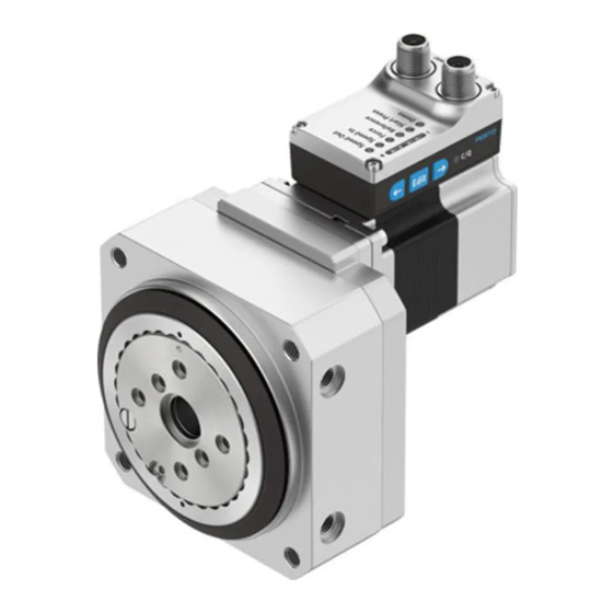
Page 5: Product Overview
The following components are included in the scope of delivery: – Rotary drive unit ERMS – Instruction manual for the rotary drive unit ERMS – Adapter for IO-Link operation (optional accessory) è www.festo.com/catalogue Function The rotation of the motor is transferred to the rotary table by a helical gear unit. -
Page 6: Product Design
8 Pushbutton actuator (left arrow) Fig. 3 Electrical connections, display and operating components (HMI) Transport NOTICE! Unexpected and unbraked movement of components • Secure moving components for transport. • Take product weight into account è 14 Technical data. Festo — ERMS — 2019-07... -
Page 7: Assembly
Mount the drive. – Tighten screws evenly. – Observe the maximum screw-in depth and tightening torque è Tab. 2. Size Screw Tightening torque [Nm] Centring [mm] 12H7 Æ Æ Max. screw-in depth (side mounting) [mm] Tab. 2 Festo — ERMS — 2019-07... - Page 8 Assembly Side mounting of drive 1 Screw 2 Centring sleeve 3 Mounting hole 4 Rotary drive unit ERMS Fig. 4 Side mounting of drive Front/rear mounting of drive 1 Screw 2 Mounting hole 3 Rotary drive unit ERMS Fig. 5 Front/rear mounting of drive...
-
Page 9: Mounting Attachment Component
– Tighten screws evenly. – Observe the maximum screw-in depth and tightening torque è Tab. 3. 1 Rotary drive unit ERMS 2 Mounting hole 3 Central drill hole 4 Central drill hole for centring sleeve 5 Mounting hole for centring sleeve 6 Screw Fig. - Page 10 Fig. 7 Wiring diagram: DIO operation (digital I/O) Wiring diagram: IO-Link operation 1 PELV fixed power supply unit for power sup- 2 IO-Link master with IO-Link interface ply 24 V DC 3 EMCS-ST Fig. 8 Wiring diagram: IO-Link operation Festo — ERMS — 2019-07...
-
Page 11: Commissioning
Severe, irreversible injuries from accidental movements of the connected actuator technology. Unintentional movements of the connected actuator technology can result from exchanging the con- necting cables of a servo drive or between servo drives. • Before commissioning: All cables must be correctly assigned and connected. Festo — ERMS — 2019-07... -
Page 12: Commissioning "Dio Operation (Digital I/O)
With the first motion task and after each restart, the position of the reference end position "Ref" is re- initialised (drive first moves to the reference end position "Ref" before the actual motion task is executed), LED "C/Q" lights green. Festo — ERMS — 2019-07... -
Page 13: Commissioning "Io-Link Operation
1. Check the assembly of the drive unit. 2. Check the wiring of the power supplies [Power] and the IO-Link interface [Logic]. 3. Install the application software. 4. Open IODD file in the application software è www.festo.com/sp. Processing 1. Switch on power voltage. -
Page 14: Dimension Reference System
(default) – right – /Lim : end positions – Mech /Mech : mechanical stops – : current position – : Start Press Position Start Press Tab. 4 Dimension reference system for rotary drive systems Festo — ERMS — 2019-07... -
Page 15: Display And Operating Components (Hmi)
– Start Press Run (Start/Stop) and Start Press Position Pos Save press. Start Press – Execute Demo Run (Start/Stop) – Lock pushbuttons (Lock HMI), 3 s press or 15 s no pushbutton entry Fig. 10 HMI menu Festo — ERMS — 2019-07... -
Page 16: Homing
– right: 0x0103.0, reference = true Control homing HMI: IO-Link (acyclic device data): – Start : menu, reference – Start 10.3 Display and operating components 0x0104.0, Execute Mov = true è (HMI) Tab. 5 Parameterise and control homing Festo — ERMS — 2019-07... -
Page 17: End-To-End Operation
Force/Torque: 0x0102.0, Force – Start Press Position Pos : 0x0105.0, Position Start Press [mm] 3)4) Start Press – End position Lim : 0x0106.0, end position Out [mm] Control end-to-end operation DIO: IO-Link (cyclic process data): Festo — ERMS — 2019-07... -
Page 18: Maintenance
Safeguard the power supply from being switched on again unintentionally. 11.1 Disassembly • Remove motor cables and retaining screws. Observe transport information è 6 Transport. 11.2 Cleaning • Clean the outside of the product with a soft cloth. Do not use aggressive cleaning agents. Festo — ERMS — 2019-07... -
Page 19: Malfunctions
Errors can be reset as follows: – DIO mode è reset of logic voltage – IO-Link operatingè parameter "Quit Error" (0x0029.3 or 0x0107.0) The first error that occurred is always displayed. Fig. 11 Display of diagnostic messages (example) Festo — ERMS — 2019-07... - Page 20 Load voltage oversupply 0x1801 (39) 0x0031 Device undertemperature 0x4000 (49) 0x0033 Device overtemperature (51) 0x012F IO-Link connection lost (303) 1) This error can only be acknowledged by a restart. Tab. 7 Diagnostic messages "Warnings and Errors" Festo — ERMS — 2019-07...
-
Page 21: Fault Clearance
Tab. 8 Fault clearance 12.2 Repair Send the product to the Festo repair service for repair. Disposal Dispose of the product and packaging at the end of its useful life through environmentally friendly recycling in accordance with applicable regulations. -
Page 22: Technical Data
In the case of low set force levels, the influence of friction in the system on the running behaviour and the actual force on the rotary drive must also be taken into account. 4) derating 5) Distance (MechIn –LimIn or MechOut –LimOut) Tab. 9 Technical data ERMS Festo — ERMS — 2019-07... - Page 23 200 160 200 … … Shock load Acceleration [m/s Duration [ms] Shocks per direction ± ± Continuous shock load Acceleration [m/s Duration [ms] Shocks per direction 1000 ± Tab. 10 Features of severity level (SL) Festo — ERMS — 2019-07...
- Page 24 Copyright: Festo AG & Co. KG Ruiter Straße 82 73734 Esslingen Germany Reproduction, distribution or sale of this document or communic- Phone: ation of its contents to others without express authorization is +49 711 347-0 prohibited. Offenders will be liable for damages. All rights...
Need help?
Do you have a question about the ERMS and is the answer not in the manual?
Questions and answers