Table of Contents
Advertisement
Quick Links
Advertisement
Table of Contents

Related Manuals for Omega TRCN443


Summary of Contents for Omega TRCN443
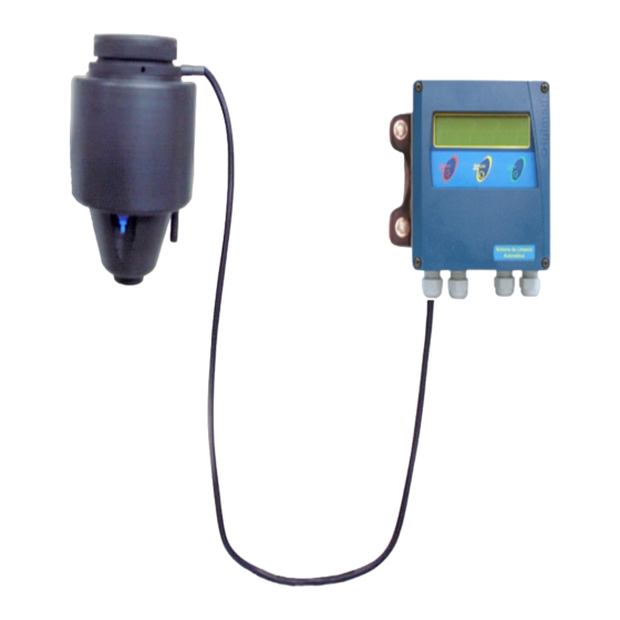
- Page 1 TRCN443 Low Turbidity Analyzer...
-
Page 3: Table Of Contents
Instruction Manual Low Turbidity Meter TRCN443 Index Specifications ..........3 Machanical Description . -
Page 4: Specifications
2. Specifications APPLICATION Analyzer / Transmiter / Turbidity Controller ANALYZER Display Alphanumeric 2 lines x 16 characters Range 0.0001 to 10 NTU Resolution 0.0001 (0.0001 thru 5NTU) / 0.001 (5.001 thru 10NTU) Relative Precision 0.01% (full scale) Analytical Method Nephelometric Wavelength 660 nm GENERAL... -
Page 5: Machanical Description
3. Mechanical Description The equipment is offered in a compact cast aluminum case, SAE-323 with lower oxidation power, treated against corrosion, finished with epoxy-electrostatic paint and expanded polypropylene panels (PU). With reduced dimensions and very light weight, is build under IP-67 protection. Under the same case, user will find: Local Indicator, Analyzer, Transmitter and Controller of ease operation. -
Page 6: Turbidity Measurement Principle
This can cause the measurement to be skewed. The OMEGA Turbidity Meter LED light source emits at a range close to infrared. In this range absorption is minimized, and turbidity measurements are more accurate. - Page 7 4. Turbidity Measurement Principles (cont.) Vial Transmitted 90° Light Light Emitting near “ IR” Reflected Light @ 90° Detector As detection involves the difference between the light reaching the vial and transmitted by the sample placed at the cuvette, it is convenient to minimize the effects that diminish the light intensity transmitted, among those the most important, it is the absorption caused by the samples color.
-
Page 8: Dimensional
5. Dimensional Below you will find panel dimensional for installation in flat surface and distances between support holes. Seleção Entra Escape Electrical Power Cable Length Dimensions in Millimeters ITEM DESCRIPTION Hose ½” Drainage Bubble Trapper (remove bubbles) in Black PP PU Hose - Diam. -
Page 9: Equipment Installation
3.1.4. Do not cut or try to attach the connection cable. In case you need to change it s length, Contact OMEGA Customer Service. RF Shield Meas. Sensor Cable Yellow Green Electr. Shield 3.1.5. -
Page 10: Interconnection Barr
7. Interconnection Barr CN2 - Connector 2 Slots Connection 1 and 2 Electrical Power for 90/240 Vac 50/60Hz connection Ground 4 and 5 SP2 - Set-Point 2 for alarm or control 6 and 7 SP1 - Set-Point 1 for alarm or control 8 and 9 Digital Transmission Output 4 to 20 mA 10 and 11... -
Page 11: Electrical Schematic
8. Electrical Schematic Shie Gre. Yellow Colorless RF Shield... -
Page 12: Lens & Bubble Trap Cleaning
9. Lens and Bubble Trap Cleaning Sensor Unit Lens and Bubble Trapper Cleaning LENS CLEANING OF SENSOR UNIT Remove the Sensor/Turbidity Detector (5) by turning it clockwise (45degrees) and pull it up. Using a soft sponge and neutral soap, wash the Led and the photocell Lenses. After this, dry it using a soft Absorbent paper, a type that will not leave residues. - Page 13 9. Bubble Trap Cleaning (cont.) Remove the Bubble Trapper by pulling it up. Bubble Trapper Body Totally remove the Bubble Trapper from the body. Wash it using neutral soap and a small brush, using circular movements, clean the openings. Rinse using plenty of water and dry it using a soft absorbent paper, a type that will not leave residues.
-
Page 14: Calibration Information
10. Calibration Information 1) Prepare the calibration standards need for your application (see page 14 for instructions on how to formulate standards). 2) Close the process Sample Inlet. 3) Un-thread the Drainage Lid, in order to remove the sample located inside the Bubble Trapper. 4) Remove the Sensor Unit from the Bubble Trapper and insert the calibration cup, as shown below. -
Page 15: Turbidity Standards
11. Turbidity Standard Instructions on how to prepare Calibration Solutions 1. Standard Zero In order to obtain a turbidity close to Zero, use a good quality deionized or distilled water and filter it twice in a roll, using a 0.2 µm filter and teorically you will obtain a water with 0.12NTU, that can be considered Zero (Blank). -
Page 16: Equipment Operation
12. Equipment Operation Set Up Procedures The equipment offers a non-volatil memory (E2PROM), in order to store operations functions (resolution, reading, Calibration and more). Even when turned off from power, all functions chosen during set up will remain stored. Before starting any work with the equipment, it is recommended to verify the SET UP parameters, to certify that you have chosen the correct options for the operation . -
Page 17: Equipment Operation - Turning On
At every touch the screen will move back one step back. While in Reading Mode, <E SCAPE> key must be pressed and hold for about 6 seconds to exit this mode and return to main menu. OMEGA MOD:TRCN443 V1.0 DISPLAY TEST »»»»»»»»»»»»»»»» »»»»»»»»»»»»»»»» Interpreting the Read menu. The Set Points will be S1:» S2:»... -
Page 18: Equipment Opeartion - Set Up
12. Equipment Operation - Set Up TURBIDIMETER Press <SEL> until Set Up flashes then press <ENT> key. READ/SET UP A Password is required in order to access the PASSWORD . Press in sequence <SEL> <ENT> <ESC> In order to select the desired language, press LANG.: PORT./ <SEL>... - Page 19 12. Equipment Operation - Set Up (cont.) From Page 17 DISPLAY CONFIG.? User can program the display to show information like Barr graph, Clock and more. User can choose if desire to have Barr graph shown BARGRAPH? above the Reading screen. When Bar Graph is displayed, the information about Sensibility and Sample Temperature will not be displayed! User can now adjust the Minimum and Maximum...
- Page 20 12. Equipment Operation - Set Up (cont.) User can adjust the value for SP 2. Refer to Page 16 (Note A) for instruction on how to adjust SET POINT S2: this value. Resolution will depend upon the Resolution 20.0000 NTU <>...
- Page 21 12. Equipment Operation - Set Up (cont.) User will have the option to configure digital output RS-485 RS-485 CONFIG.? for Proprietary or Modbus Protocol. Press <SELECT> to choose the desired option then press <ENTER> key to confirm . User will be able to define the instrument identification COMMUNICATION-ID number within the network, up to 32 instruments.
-
Page 22: Equipment Operation - Calibration
12. Equipment Operation - Calibration Before initiating the Calibrtion Procedure, preapre the Standard Solutions and have the deionized water ready. Also clean the Calibration Reservoir using deionized waterat every change of Standard Solution. TURBIDIMETER Press <SEL> until Read flashes then press <ENT>... -
Page 23: Equipment Opearation - Read
12. Equipment Operation - Read Find below instructions on how to perform a Turbidity Reading. Before starting, verify if the bubble trapper is clean, if the drain hose is connected and “open” and if the sample is flowing correctly. Finally insert the sensor unit at the bubble trapper and lock it by turning it counter clockwise (45degrres). -
Page 24: Communication Protocol
13. Proprietary Communication Protocol Communication Protocol (TRCN-443): 1) Proprietary: Order: 0x1B 0x50 0x0D 0x0A Hexadecimal The ID is configured at the instrument from 1 to 32. Answer: L > > V V V V V V N T U C C C C C C m A Example of answer for an un-stable value (for low turbidity 0 –... - Page 26 M-4513/0908...
Need help?
Do you have a question about the TRCN443 and is the answer not in the manual?
Questions and answers