Table of Contents
Advertisement
Advertisement
Table of Contents

Subscribe to Our Youtube Channel
Related Manuals for Omega FLR 1000


Summary of Contents for Omega FLR 1000
- Page 1 FLR 1000/1000BR/1000ST Series Flow Sensors & Meters For Liquids...
-
Page 3: Table Of Contents
READ THIS MANUAL COMPLETELY BEFORE ATTEMPTING TO CONNECT OR OPERATE YOUR FLOW SENSOR. FAILURE TO DO SO MAY RESULT IN INJURY TO YOU OR DAMAGE TO THE FLOW SENSOR. T A B L E C O N T E N T S Introduction ...................4 1. -
Page 4: Introduction
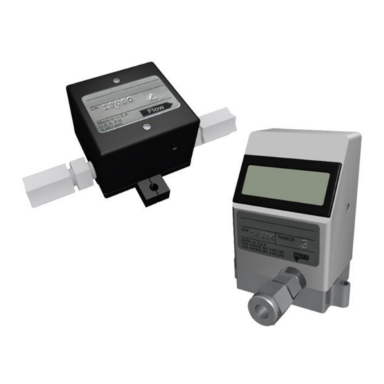
Omega Engineering to resolve the problem. Typical Contents of Box: Sensor, Calibration Certificate & Instruction Manual (Model FLR 1000 shown, other models similar). FLR 3100/3100BR/3100ST Series & M... -
Page 5: Product Overview And Principle Of Operation
Product Overview and Principle of Operation The FLR 1000 series of flow meters and sensors for liquids from Omega Engineering are capable of measuring flows as low as 13-100 ml/min or as high as 1.0-10.0 l/min. Highly repeatable results are achieved using a patented Pelton Turbine Wheel flow sensor design. -
Page 6: Installation
Do not exceed the pressure, temperature or power operating ranges detailed in the SPECIFICATIONS section of this manual. Omega Engineering shall not be liable for any damage or injury caused by incorrect operation of their products. -
Page 7: Mounting The Flow Sensor Or Flow Meter
(see section C2 for details of how to remove entrapped air or gas). Mounting the Flow Sensor or Flow Meter. The Omega Engineering FLR 1000 Series units have no particular installation requirements so may be mounted in any convenient position. -
Page 8: Tubing Connections
Only use the fittings factory installed on the unit. If the fittings are removed the calibration of the unit may be effected and leaking may occur. If different fittings are required please contact the Omega Engineering Service Department for assistance. -
Page 9: Electrical Connections
Overview The FLR 1000 series of flow sensors and flow meters provide a 0-5VDC, or 4-20mA, or 0-5VDC and pulse output proportional to the flow rate. This output may be connected to a display, data acquisition system or voltmeter / current meter. -
Page 10: B) Connecting A Cable Assembly
The FLR 1000-D, 1000-ST-D and 1000-BR-D series feature an integral display that provides a local flow reading. These units also have a 0-5VDC analog output available. If required, this may be connected to another display, data acquisition system or voltmeter. -
Page 11: C) Electrical Connections - Voltage Output Units
Electrical Connections – Voltage Output Units The cable assembly should be connected to the sensor as detailed in section 5(b) above. Power should not be applied to the sensor until all the connections have been made and checked. Electrical connections should be made as follows: Wiring Schematic For Voltage Output Units. -
Page 12: D) Electrical Connections - Units With Both Voltage & Pulse Outputs
Electrical Connections –Units with Both Voltage and Pulse Outputs The cable assembly should be connected to the sensor as detailed in section 5(b) above. Power should not be applied to the sensor until all the connections have been made and checked. Electrical connections should be made as follows: Wiring Schematic For Voltage and Pulse Output. -
Page 13: E) Electrical Connections - Current Output Units ("I" Suffix)
Electrical Connections – Current Output Units (“I” Suffix) The FLR 1000–ST-I provides a 4-20mA active current output proportional to the flow rate. The cable assembly should be connected to the sensor as detailed in section 5(b) above. Power should not be applied to the sensor until all the connections have been made and checked. -
Page 14: F) Using A 0-5Vdc Output Power Adapter Package
Using a 0-5VDC Output Power Adapter Package. An optional 0-5VDC Output Power Adapter Package is available for use with the FLR 1000 series (not the FLR 1000-ST-I). This consists of a power source (115VAC or 230VAC) and cable assembly with pig-tail (soldered wire) ends for the signal output. -
Page 15: Operation
Flow Readings The FLR 1000 Series provide a 0-5VDC, or 4-20mA (I suffix), or 0-5VDC and pulse output (P suffix) proportional to the flow rate. The type of output signal is detailed by the part number reference and on the calibration certificate. -
Page 16: A) 0-5Vdc Analog Outputs
0-5VDC Analog Outputs By monitoring the voltage output signal it is possible to determine the flow rate of the liquid. Units are configured so that an output signal of 5.0VDC is provided when the maximum flow (i.e. Full Scale flow) is passing through the unit. -
Page 17: D) Units With An Integral Display
200 ÷ (20-4) × 9 = 112.5ml/min Units With an Integral Display The FLR 1000-D, FLR 1000-BR-D and FLR 1000-ST-D series features an integral 3 ½ digit LCD display. This is configured to read in ml/min for flow ranges up to 50-500 ml/min and in l/min for flow ranges of 0.1 – 1.0 L/min. -
Page 18: A) Flows Above The Maximum Rated Flow
These methods should only be used to gain an indication of a sensor’s performance. Please contact the Omega Engineering Service Department if accurate, certified recalibration is required. A typical empirical calibration check may be carried out as follows: Carefully adjust the flow rate so that the maximum output signal is obtained. - Page 19 If there is a big difference in the percentage errors then the flow signal is no longer linear and the unit may be damaged (consult the Omega Engineering Service Department).
-
Page 20: Calibrating Units For Different Liquids
Corrected flow rate = Uncorrected flow rate + error = 1.4 + 5% = 1.47 l/min Calibrating Units for Different Liquids The FLR 1000 Series will operate with most translucent liquids subject to compatibility of the wetted parts. Best results are obtained with low viscosity (less than 10 centistokes) liquids. For information regarding higher viscosity liquids, contact the Omega Engineering Service Department. -
Page 21: Maintenance And Product Care
If the unit appears to be malfunctioning please contact the Omega Engineering Service Department. The FLR 1000 Series of flow meters and sensors require no periodic maintenance if used within the recommended specifications. The next recommended recalibration date is stated on the calibration certificate supplied with the unit. -
Page 22: Specifications
Specifications For Liquid Units FLR 1000 FLR 1000-BR FLR 1000-ST FLR 1000-ST-I Analog Signal Accuracy ±1.0% Full Scale (including linearity) Repeatability ±0.2% Full Scale Pressure Rating 100 psig 500 psig (6.8 bar) (34.5 bar) Temperature Rating Operating Range: 5 to 55ºC Storage Range: 0 to 70ºC... - Page 23 FLR 1000-D FLR 1000-BR-D FLR 1000-ST-D Display 3.5 Digit Non Backlit LCD, 0.39” (10mm) high digits Accuracy ±1.0% Full Scale (including linearity) Repeatability ±0.2% Full Scale Pressure Rating 100 psig 500 psig (6.8 bar) (34.5 bar) Temperature Rating Operating Range: 5 to 55ºC Storage Range: 0 to 70ºC...
-
Page 24: Dimensions
Dimensions ALL DIMENSIONS IN INCHES (MILLIMETERS IN BRACKETS) FLR 1000 For Liquids 1/4” Acetal Fittings Shown pg. 24 of 33... - Page 25 FLR 1000-BR & FLR 1000-ST For Liquids 1/4” Compression Fittings Shown pg. 25 of 33...
- Page 26 FLR 1000-ST-I For Liquids 1/4” Fittings Shown pg. 26 of 33...
- Page 27 FLR 1000-D For Liquids 1/4” Acetal Fittings Shown pg. 27 of 33...
- Page 28 FLR 1000-BR-D & FLR 1000-ST-D For Liquids 1/4” Compression Fittings Shown pg. 28 of 33...
-
Page 29: Connector Pin And Wire Color Cross Reference
Connector Pin And Wire Color Cross Reference End On View of Connector Socket and Connector Standard Units: Cable Wire Unit Output Color Voltage Voltage & Current Pulse Black Signal & Power Signal & Power Signal & Power Negative Negative Negative (Ground) (Ground) (Ground) -
Page 30: Troubleshooting Guide
Allow unit to dry out in a electronics dry environment. Output circuitry damaged Unit must be returned for repair (see Section D3) Liquid not translucent Contact the Omega enough. Engineering Service Department for assistance. Attempting to measure Use higher flow rates. - Page 31 Liquid is too viscous Best results are obtained with liquids that have a viscosity of 10cS or less. Contact the Omega Engineering Service Department for further information Entrapped air or gas Remove entrapped air...
- Page 32 pg. 32 of 33...
- Page 33 M4574/0807 pg. 33 of 33...
Need help?
Do you have a question about the FLR 1000 and is the answer not in the manual?
Questions and answers