Table of Contents
Advertisement
Quick Links
Advertisement
Table of Contents

Related Manuals for KTM 890 ADVENTURE 2022


Summary of Contents for KTM 890 ADVENTURE 2022
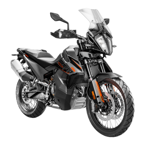
- Page 1 OWNER'S MANUAL 2022 890 ADVENTURE 890 ADVENTURE L Art. no. 3214534en...
- Page 3 KTM accepts no liability for delivery options, deviations from fig- ures and descriptions, misprints, and other errors. The models portrayed partly contain special equipment that does not belong to the regular scope of supply.
-
Page 4: Table Of Contents
TABLE OF CONTENTS Switches on the right side of the TABLE OF CONTENTS MEANS OF REPRESENTATION ...... 6 handlebar........19 Symbols used ........6 6.5.1 Start button/emergency OFF Formats used........6 switch......... 19 Ignition and steering lock....20 SAFETY ADVICE..........7 Locking the steering ...... - Page 5 7.25 Navigation display......38 Setting the front rider's seat....61 7.26 Menu..........39 Handlebar position......61 7.26.1 KTM MY RIDE ......39 Adjusting the handlebar position ..61 7.26.2 Audio ......... 39 Adjusting the windshield ....62 7.26.3 Navigation........40 Adjusting the basic position of the 7.26.4...
- Page 6 TABLE OF CONTENTS 13.4 Taking the motorcycle off the front 15.5 Checking the rear hub damping lifting gear ........84 rubber pieces ......116 13.5 Removing the passenger seat .... 84 15.6 Checking the tire condition ..... 117 13.6 Mounting the passenger seat..... 85 15.7 Checking tire pressure ....
- Page 7 TABLE OF CONTENTS 22 TROUBLESHOOTING ........ 144 23 TECHNICAL DATA........146 23.1 Engine .......... 146 23.2 Engine tightening torques ....147 23.3 Capacities ........149 23.3.1 Engine oil ......... 149 23.3.2 Coolant ........149 23.3.3 Fuel ......... 150 23.4 Chassis ......... 150 23.5 Electrical system......
-
Page 8: Means Of Representation
Indicates work that requires expert knowledge and technical understanding. In the interest of your own safety, have these jobs performed by an authorized KTM workshop! Your motorcycle will be cared for there to the highest degree by specially trained experts using the special tools required. -
Page 9: Safety Advice 2
SAFETY ADVICE 2 Use definition – intended use The vehicle is designed and constructed to withstand the usual demands of regular traffic and use on gentle ter- rain (unpaved roads). This vehicle is not suitable for use on race tracks. Info This vehicle is only authorized for operation on public roads in its homologated version. -
Page 10: Tampering Warning
The vehicle should only be used by trained persons. An appropriate driver's license is needed to ride the vehicle on public roads. Have malfunctions that impair safety promptly eliminated by an authorized KTM workshop. Adhere to the information and warning labels on the vehicle. -
Page 11: Protective Clothing
– Always wear protective clothing that is in good condition and meets the legal regulations. In the interest of your own safety, KTM recommends that you only operate the vehicle while wearing protective clothing. Work rules Unless specified otherwise, the ignition must be turned off during all work (models with ignition lock, models with remote key) or the engine must be at a standstill (models without ignition lock or remote key). - Page 12 The Owner's Manual can be downloaded several times using the QR code or the link on the delivery certificate. The Owner's Manual is also available for download from your authorized KTM dealer and on the KTM website. A printed copy can also be ordered from your authorized KTM dealer.
-
Page 13: Important Notes 3
Manufacturer warranty, implied warranty The work prescribed in the service schedule must only be carried out in an authorized KTM workshop and con- firmed in the KTM Dealer.net, as otherwise all warranty claims will be void. Damage or secondary damage caused by tampering with and/or conversions on the vehicle are not covered by the manufacturer warranty. -
Page 14: View Of Vehicle
4 VIEW OF VEHICLE View of vehicle, front left (example) F03278-10 Socket for electrical accessories ( p. 21) Clutch lever ( p. 16) Seat lock ( p. 26) Storage compartment on the left Grab handles ( p. 26) Luggage rack plate ( p. -
Page 15: View Of Vehicle, Rear Right (Example)
VIEW OF VEHICLE 4 View of vehicle, rear right (example) F03279-10 Storage compartment under the passenger seat Storage compartment on the right Light switch ( p. 17) Menu buttons ( p. 18) Turn signal switch ( p. 19) Horn button ( p. -
Page 16: Serial Numbers
5 SERIAL NUMBERS Vehicle identification number The vehicle identification number is stamped on the right side of the steering head. 402324-10 Type label The type label is located on the frame on the left. The type label for Australia is located on the frame on the right. -
Page 17: Engine Number
SERIAL NUMBERS 5 Engine number The engine number is stamped onto the engine case at the top. H01047-10 Fork part number The fork part number is stamped on the inner side of the fork stub. 402295-10 Shock absorber article number Shock absorber article number is attached the top of the shock absorber. -
Page 18: Controls
6 CONTROLS Clutch lever Clutch lever is fitted on the handlebar on the left. F01882-10 Hand brake lever The hand brake lever is fitted on the right side of the handle- bar. The front brake is engaged using the hand brake lever. F01883-10 Throttle grip The throttle grip... -
Page 19: Light Switch
CONTROLS 6 6.4.2 Light switch The light switch is fitted on the combination switch on the left. Possible states Low beam on – Light switch in position . In this position, the low beam and the tail light are switched High beam on –... -
Page 20: Menu Buttons
6 CONTROLS In addition, the cruise control system function is deactivated when one of the following events occurs: – Operating the hand brake lever – Operating the foot brake lever – Operating the clutch lever – Turning the throttle grip beyond the basic position –... -
Page 21: Turn Signal Switch
CONTROLS 6 6.4.5 Turn signal switch Turn signal switch is fitted on the combination switch on the left. Possible states Turn signal off Left turn signal, on – Turn signal switch pressed to the left. The turn signal switch returns to the center position after activation. -
Page 22: Ignition And Steering Lock
6 CONTROLS Ignition and steering lock The ignition and steering lock is located in front of the upper triple clamp. Possible states Ignition off – In this position, the ignition circuit is interrupted, a running engine stops, and a non-running engine will not start. The ignition key can be removed. -
Page 23: Socket For Electrical Accessories
CONTROLS 6 Socket for electrical accessories Socket for electrical accessories is fitted in front of the upper triple clamp. It is connected to the ignition plus and is fuse-protected. Socket for electrical accessories Voltage 12 V Maximum cur- 10 A rent consump- tion F01922-10... -
Page 24: Closing The Fuel Tank Filler Cap
6 CONTROLS 6.11 Closing the fuel tank filler cap – Fold down the fuel tank filler cap. – Turn the ignition key 90° clockwise. – Push down the fuel tank filler cap and turn the ignition key counterclockwise until the lock closes. Warning Fire hazard Fuel is highly flammable, toxic and a health hazard. -
Page 25: Closing The Storage Compartment Under The Passenger Seat
CONTROLS 6 Main work – Lift the lock in the direction of the arrow and detach in area – Open storage compartment. F01892-10 6.14 Closing the storage compartment under the passenger seat Main work – Close the storage compartment. – Attach lock in area and press down in the direction of... -
Page 26: Opening The Storage Compartment On The Left
6 CONTROLS 6.15 Opening the storage compartment on the left Preparatory work – Remove the passenger seat. ( p. 84) – Remove the front rider's seat. ( p. 85) – Remove the left side cover. ( p. 90) Main work –... -
Page 27: Opening The Storage Compartment On The Right
CONTROLS 6 6.17 Opening the storage compartment on the right Preparatory work – Remove the passenger seat. ( p. 84) – Remove the front rider's seat. ( p. 85) – Remove the right side cover. ( p. 91) Main work –... -
Page 28: Tool Set
6 CONTROLS 6.19 Tool set The left or right storage compartment contains the on-board tool F01905-10 6.20 Grab handles The grab handles are used for moving the motorcycle around. If you carry a passenger, the passenger can hold onto the grab handles during the trip. -
Page 29: Passenger Foot Pegs
CONTROLS 6 6.23 Passenger foot pegs The passenger foot pegs can be folded up and down. Possible states Passenger foot pegs folded up – For operation without a pas- • senger. Passenger foot pegs folded down – For operation with a pas- •... -
Page 30: Side Stand
6 CONTROLS 6.26 Side stand The side stand is located on the left of the vehicle. The side stand is used for parking the motorcycle. Info The side stand must be folded up during motorcycle use. The side stand is coupled with the safety starting system; follow the riding instructions. -
Page 31: Combination Instrument 7
(taking care not to endanger yourself or other road users in the pro- cess) and contact an authorized KTM workshop. The oil pressure warning lamp always lights up as long as the engine is not running. If the engine is running and... -
Page 32: Warnings
7 COMBINATION INSTRUMENT Night mode is shown in a dark color. Info The ambient light sensor in the combination instrument measures the brightness of the environment. The display is brightened, darkened or switched to the other mode depending on the light intensity measured by the ambient light sensor. -
Page 33: Indicator Lamps
TC indicator lamp lights up/flashes yellow – MTC ( p. 135) is not enabled or is currently intervening. The TC indicator lamp also lights up if a malfunction is detected. Contact an authorized KTM workshop. The TC indicator lamp flashes, if MTC or MSR (optional) actively engage. -
Page 34: Display
7 COMBINATION INSTRUMENT The oil pressure warning lamp lights up red – The oil pressure is too low. Stop immediately, taking care not to endanger yourself or other road users in the process, and switch off the engine. The alarm system indicator lamp lights up or flashes red – Status or error message of the alarm system. -
Page 35: Rally Display (Optional)
COMBINATION INSTRUMENT 7 MTC display ( p. 36) Cruise control indicator (optional) ( p. 36) Coolant temperature indicator ( p. 36) Fuel level display ( p. 37) Ambient air temperature indicator ( p. 37) Ice warning ( p. 30) Bluetooth ®... -
Page 36: Speed
7 COMBINATION INSTRUMENT Speed The speed is measured in revolutions per minute. F01771-01 7.10 Shift warning light The shift warning light is integrated in the tachometer display. In the Shift Light submenu, the engine speed for the shift warning light can be set. The shift warning light is always active during the running-in phase (up to 1,000 km / 621 mi). -
Page 37: Heated Grip (Optional)
COMBINATION INSTRUMENT 7 7.12 Heated grip (optional) When the heated grip is switched on, the Heating Grip symbol appears in the area of the display. The heated grip can be configured in the Heating Grip submenu (optional function). F03311-10 7.13 Seat heating (optional) When the seat heating is switched on, the Heating Seat symbol appears in area... -
Page 38: Mtc Display
7 COMBINATION INSTRUMENT 7.16 MTC display area of the display indicates whether MTC ( p. 135) is switched on or off. The motorcycle traction control can be switched on or off in the MTC submenu. F01775-12 7.17 Cruise control indicator (optional) When cruise control (optional) is activated, the operating mode is displayed on the combination instrument display. -
Page 39: Fuel Level Display
COMBINATION INSTRUMENT 7 7.19 Fuel level display The fuel level display consists of bars. The more bars are lit, the more fuel is in the fuel tank. Info Measurement of the fuel supply only becomes active after reaching half of the fuel tank content. Up to half of the fuel tank content, the fuel level display will be shown as full. -
Page 40: Favorites Display
7 COMBINATION INSTRUMENT 7.22 Favorites display Up to eight items of information are shown in the Favorites display. The Favorites display can be freely configured in the Favorites sub- menu. Info One to four items of information selected are displayed on two lines. -
Page 41: Menu
Press the SET button when the menu is closed. – Press the UP or DOWN button until KTM MY RIDE is marked. Press the SET button to open the menu. In the KTM MY RIDE menu, an appropriate cellphone or headset can be paired with the combination instrument via Bluetooth ®... -
Page 42: Navigation
Condition Function Bluetooth ® • activated. • The KTM MY RIDE Navigation app is installed and opened on a suitable cellphone (Android ® devices Version 6.0 and higher, iOS devices Version 10 and higher). • The combination instrument is connected to a suitable cell- phone. -
Page 43: Phone
– Press the SET button when the menu is closed. – Press the UP or DOWN button until KTM MY RIDE is marked. Press the SET button to open the menu. – Press the UP or DOWN button until Pairing is marked. Press F01792-01 the SET button to open the submenu. -
Page 44: Headset
– Press the SET button when the menu is closed. – Press the UP or DOWN button until KTM MY RIDE is marked. Press the SET button to open the menu. – Press the UP or DOWN button until Pairing is marked. Press F01793-01 the SET button to open the submenu. -
Page 45: Telephony
COMBINATION INSTRUMENT 7 7.26.7 Telephony Condition • Function Bluetooth ® activated. • The Bluetooth ® function should also be activated in the device to be paired. • The combination instrument is connected to a suitable cell- phone. • The combination instrument is connected to a suitable head- set. -
Page 46: General Info
7 COMBINATION INSTRUMENT 7.26.9 General Info – Press the SET button when the menu is closed. – Press the UP or DOWN button until Trips/Data is marked. Press the SET button to open the menu. – Press the UP or DOWN button until General Info is marked. Press the SET button to open the submenu. -
Page 47: Tpms (Function Optional)
COMBINATION INSTRUMENT 7 Info Trip shows the distance since the last reset, such as between two refueling stops. Trip is running and counts up to 9999. ØCons indicates the average fuel consumption based on Trip. ØSpeed indicates the average speed based on Trip and Trip Time. -
Page 48: Warning
7 COMBINATION INSTRUMENT 7.26.13 Warning Condition • Message or warning is present. – Press the SET button when the menu is closed. – Press the UP or DOWN button until Trips/Data is marked. Press the SET button to open the menu. –... -
Page 49: Rally (Optional)
COMBINATION INSTRUMENT 7 Warning Danger of accidents An incorrectly selected riding mode makes control of the vehicle considerably more difficult. The riding modes are each only suitable for certain conditions. – Always select a riding mode that suits the surface on which you are riding, the weather and the riding situation. -
Page 50: Throttle Response (Optional)
7 COMBINATION INSTRUMENT 7.26.17 Throttle Response (optional) Condition • Model with RALLY PACK. • The riding mode Rally (optional) is activated. – Press the SET button when the menu is closed. Warning Danger of accidents An incorrectly selected riding mode makes control of the vehicle considerably more difficult. -
Page 51: Motorcycle
COMBINATION INSTRUMENT 7 – Press the UP or DOWN button until Leave Rally is marked on the display. Press the SET button to end riding mode Rally and automatically switch to riding mode Street. Info Do not open the throttle when deactivating riding mode Rally. -
Page 52: Mtc+Msr (Optional)
7 COMBINATION INSTRUMENT 7.26.21 MTC+MSR (optional) Condition • Model with MTC+MSR. • Cruise control system function (optional) deactivated. – Press the SET button when the menu is closed. – Press the UP or DOWN button until Motorcycle is highlighted. Press the SET button to open the menu. –... -
Page 53: Heating Grip (Function Optional)
COMBINATION INSTRUMENT 7 Info The ABS mode can be switched during the journey. Do not open the throttle during the selection. When the ABS mode Road is active, ABS controls both wheels. When the Offroad ABS mode is active, ABS only con- trols the front wheel. -
Page 54: Settings
7 COMBINATION INSTRUMENT – Press the SET button to switch quickshifter + ( p. 71) button on or off. 7.26.26 Settings Condition • The motorcycle is stationary. – Press the SET button when the menu is closed. – Press the UP or DOWN button until Settings is marked. Press the SET button to open the menu. -
Page 55: Quick Selector 2
F01813-01 off. Info The Bluetooth ® function can only be used in conjunction with KTM MY RIDE. If a device has been paired via the submenu Pairing but is currently not connected, the Bluetooth ® symbol flashes when the Bluetooth ®... -
Page 56: Shift Light
7 COMBINATION INSTRUMENT Info In both modes, the display is brightened or dimmed depending on the amount of ambient light. 7.26.32 Shift Light Condition • The motorcycle is stationary. • ODO > 1,000 km (621 mi). – Press the SET button when the menu is closed. –... -
Page 57: Shift Light
COMBINATION INSTRUMENT 7 Info If the engine speed reaches the set value RPM2, the shift warning light flashes and the color changes. 7.26.35 Shift Light Condition • The motorcycle is stationary. • ODO > 1,000 km (621 mi). – Press the SET button when the menu is closed. –... -
Page 58: Drl
Make sure that the daytime running light is deac- tivated with the diagnostics tool when the menu item is not available, but the low beam is required. (Your authorized KTM workshop will be glad to help.) – Note the legal regulations regarding the daytime running light. -
Page 59: Units
COMBINATION INSTRUMENT 7 7.26.38 Units Condition • The motorcycle is stationary. – Press the SET button when the menu is closed. – Press the UP or DOWN button until Settings is marked. Press the SET button to open the menu. –... -
Page 60: Language
7 COMBINATION INSTRUMENT 7.26.42 Language Condition • The motorcycle is stationary. – Press the SET button when the menu is closed. – Press the UP or DOWN button until Settings is marked. Press the SET button to open the menu. –... -
Page 61: Heating Seat Rider (Function Optional)
COMBINATION INSTRUMENT 7 7.26.45 Heating Seat Rider (function optional) Condition • Model with seat heater. • The motorcycle is stationary. – Press the SET button when the menu is closed. – Press the UP or DOWN button until Settings is highlighted. Press the SET button to open the menu. -
Page 62: Extra Functions
– Use the UP or DOWN button to navigate through the extra func- F03324-01 tions. Info The optional extra functions are listed. The current KTM PowerParts and the available software for your vehicle can be found on the KTM website. -
Page 63: Ergonomics 8
ERGONOMICS 8 Setting the front rider's seat Preparatory work – Remove the passenger seat. ( p. 84) – Remove the front rider's seat. ( p. 85) Alternative 1 – Attach the front rider's seat to the fuel tank at the recesses , and push the front rider's seat down and forward at the same time. -
Page 64: Adjusting The Windshield
8 ERGONOMICS – Remove screws . Take off the handlebar clamps . Posi- tion the handlebar so that screws are accessible. Info Cover the components to protect them against damage. Do not kink the cables and lines. – Remove screws . -
Page 65: Adjusting The Basic Position Of The Clutch Lever
ERGONOMICS 8 Alternative 2 – Remove screw and windshield – Position windshield in upper recess – Mount and tighten screw Guideline Remaining screws, 5 Nm (3.7 lbf ft) chassis F01923-10 Adjusting the basic position of the clutch lever – Push clutch lever forward. –... -
Page 66: Adjusting Foot Brake Lever Stub
8 ERGONOMICS Info Turn the adjusting screw clockwise to decrease the distance between the hand brake lever and the han- dlebar. Turn the adjusting screw counterclockwise to increase the distance between the hand brake lever and the han- dlebar. The range of adjustment is limited. Only turn the adjusting screw by hand, and do not use force. -
Page 67: Checking The Basic Position Of The Shift Lever
ERGONOMICS 8 – Detach spring – Loosen nut Press the foot brake lever downwards to make this eas- ier. – Turn the push rod to set the basic position of the foot brake lever. F02003-10 Info The range of adjustment is limited. The screw must be screwed in by at least five full turns. -
Page 68: Adjusting The Basic Position Of The Shift Lever
8 ERGONOMICS – Sit on the vehicle in the riding position and determine distance between the upper edge of your boot and the shift lever. Distance between shift lever 10 … 20 mm (0.39 … and upper edge of boot 0.79 in) »... -
Page 69: Preparing For Use 9
When using your vehicle, remember that others may feel disturbed by excessive noise. – Make sure that the pre-sales inspection work has been carried out by an authorized KTM workshop. You will receive a delivery certificate when the vehicle is handed over. -
Page 70: Running In The Engine
9 PREPARING FOR USE – Run the engine in. ( p. 68) Running in the engine – During the running-in phase, do not exceed the specified engine speed. Guideline Maximum engine speed During the first: 1,000 km (620 mi) 6,500 rpm After the first: 1,000 km (620 mi) 9,800 rpm –... - Page 71 PREPARING FOR USE 9 Warning Danger of accidents Pieces of luggage which have slipped impair the handling characteristic. – Check that your luggage is fixed properly at regular intervals. Warning Fire hazard The hot exhaust system may burn luggage. – Fasten your luggage in such a way that it cannot be burned or singed by the hot exhaust system. –...
-
Page 72: Riding Instructions
10 RIDING INSTRUCTIONS 10.1 Checks and maintenance measures when preparing for use Info Before every trip, check the condition of the vehicle and ensure that it is roadworthy. The vehicle must be in perfect technical condition when it is being operated. –... -
Page 73: Starting Off
RIDING INSTRUCTIONS 10 The ABS warning lamp lights up and goes back out after starting off. – Shift the transmission into neutral The green idle indicator lamp N lights up. – Press the start button/emergency OFF switch into the lower position Info Only press the start button/emergency OFF switch into... -
Page 74: Shifting, Riding
10 RIDING INSTRUCTIONS 10.5 Shifting, riding Warning Danger of accidents Abrupt load alterations can cause the vehicle to get out of control. – Avoid abrupt load alterations and sudden braking actions. – Adapt your speed to the road conditions. Warning Danger of accidents If you change down at high engine speed, the rear wheel blocks and the engine races. - Page 75 Info If unusual noises occur while riding, stop immediately (taking care not to endanger yourself or other road users in the process), switch off the engine and contact an authorized KTM workshop. – Shift into a higher gear when conditions allow (incline, road situation, etc.).
- Page 76 Contact an authorized KTM workshop. – If the malfunction indicator lamp lights up during a trip, please contact an authorized KTM workshop as soon as possi- ble. – If the general warning lamp lights up during a trip, the dis- play shows a message.
-
Page 77: Msr (Optional)
Danger of accidents A spongy pressure point on the front or rear brake reduces braking efficiency. – Check the brake system and do not continue riding until the problem is eliminated. (Your authorized KTM workshop will be glad to help.) Warning Danger of accidents The brake system fails in the event of overheating. -
Page 78: Stopping, Parking
10 RIDING INSTRUCTIONS Warning Danger of accidents Driving aids can reduce the probability of a fall only within physical limits. It is not always possible to compensate for extreme riding situations, for example with luggage loaded with a high center of gravity, varying road surfaces, steep descents or full braking without disengaging the gear. -
Page 79: Transporting
RIDING INSTRUCTIONS 10 – Switch off the ignition by turning the ignition key to the position Info If the engine is switched off with the emergency OFF switch and the ignition remains switched on at the ignition lock, power continues to flow to most electrical power consumers. This discharges the 12- V battery. - Page 80 In some countries and regions, the available fuel quality and cleanliness may not be sufficient. This will result in problems with the fuel system. – Refuel only with clean fuel that meets the specified standards. (Your authorized KTM workshop will be glad to help.) Note Environmental hazard Improper handling of fuel is a danger to the environment.
-
Page 81: Service Schedule 11
Different service intervals may apply in your country, depending on the local operating conditions. Individual service intervals and scopes may change in the course of technical developments. The most up-to-date service schedule can always be found on KTM Dealer.net. Your authorized KTM dealer will be happy to advise you. -
Page 82: Recommended Work
Final check: Check the vehicle is roadworthy and take a test ride. ○ ● ● ● ● Read out the error memory after the test ride using the KTM diagnostics tool. ○ ● ● ● ● Set the service interval display. -
Page 83: Tuning The Chassis 12
Risk of injury Parts of the shock absorber will move around if the shock absorber is detached incorrectly. The shock absorber is filled with highly compressed nitrogen. – Please follow the description provided. (Your authorized KTM workshop will be glad to help.) – Turn adjusting screw clockwise up to the last perceptible click. - Page 84 12 TUNING THE CHASSIS Info Turn clockwise to increase the spring preload; turn counterclockwise to reduce the spring preload.
-
Page 85: Service Work On The Chassis 13
SERVICE WORK ON THE CHASSIS 13 13.1 Raising the motorcycle with rear lifting gear Note Danger of damage The parked vehicle can roll away or fall over. – Park the vehicle on a firm and level surface. – Mount retaining adapter on the link fork. –... -
Page 86: Taking The Motorcycle Off The Front Lifting Gear
13 SERVICE WORK ON THE CHASSIS – Move the handlebar to the straight-ahead position. – Attach the front lifting gear with the adapters on the steering stem. Mounting pin (69329965040) Front wheel work stand, large (69329965100) – Align the front lifting gear with the fork legs. Info 402345-01 Always raise the motorcycle at the rear first. -
Page 87: Mounting The Passenger Seat
SERVICE WORK ON THE CHASSIS 13 13.6 Mounting the passenger seat – Hook holding lugs of the passenger seat into the bushings on the subframe, lower the front, and simultaneously push back- ward. – Insert locking pin into the lock housing and push down the front of the passenger seat until the locking pin engages with an audible click. -
Page 88: Checking For Chain Dirt
13 SERVICE WORK ON THE CHASSIS 13.9 Checking for chain dirt – Check the chain for coarse dirt accumulation. » If the chain is very dirty: – Clean the chain. ( p. 86) 400678-01 13.10 Cleaning the chain Warning Danger of accidents Lubricants on the tires reduces the road grip. –... -
Page 89: Checking The Chain Tension
SERVICE WORK ON THE CHASSIS 13 13.11 Checking the chain tension Warning Danger of accidents Incorrect chain tension damages components and results in accidents. If the chain is tensioned too much, the chain, engine sprocket, rear sprocket, transmission and rear wheel bearings wear more quickly. Some components may break if overloaded. If the chain is too loose, the chain may fall off the engine sprocket or the rear sprocket. -
Page 90: Checking The Chain, Rear Sprocket, Engine Sprocket, And Chain Guide
13 SERVICE WORK ON THE CHASSIS Main work – Loosen nut – Loosen nuts – Adjust the chain tension by turning adjusting screws left and right. Guideline Chain tension 2 … 5 mm (0.08 … 0.2 in) Turn the adjusting screws on the left and right so that the markings on the left and right chain adjusters are in... - Page 91 SERVICE WORK ON THE CHASSIS 13 – Shift the transmission into neutral – Pull on the lower chain section with the specified weight Guideline Weight, chain wear measure- 15 kg (33 lb.) ment – Measure distance of 18 chain rollers in the lower chain section.
-
Page 92: Removing The Left Side Cover
13 SERVICE WORK ON THE CHASSIS – Check the chain sliding guard for wear. » If continuous signs of wear to the chain are visible on the chain sliding guard in the area marked: – Change the chain sliding guard. »... -
Page 93: Installing The Left Side Cover
SERVICE WORK ON THE CHASSIS 13 13.15 Installing the left side cover Main work – Position the left side cover with holding lug on bushing and push backward. The left side cover engages under the tail part. – Press the left side cover in area into rubber bushing and press into rubber bushing in area... -
Page 94: Installing The Right Side Cover
13 SERVICE WORK ON THE CHASSIS 13.17 Installing the right side cover Main work – Position the right side cover with holding lug on bush- and push backward. The right side cover engages under the tail part. – Press the right side cover in the area into rubber bush- and press into rubber bushing in area... -
Page 95: Installing The Battery Cover
SERVICE WORK ON THE CHASSIS 13 13.19 Installing the battery cover Main work – Position the battery cover with holding lugs bushings and push downward. The battery cover engages on the left and right under the fuel tank spoiler. – Mount screws with the bushings and tighten. -
Page 96: Installing The Left Fuel Tank Spoiler
13 SERVICE WORK ON THE CHASSIS Main work – Remove screw – Remove screws F03352-10 – Remove the left fuel tank spoiler from the rubber bushing in area – Pull off the left fuel tank spoiler sideways and remove it toward the front. -
Page 97: Removing Right Fuel Tank Spoiler
SERVICE WORK ON THE CHASSIS 13 – Mount screws , but do not tighten yet. Guideline Screw, trim 3 Nm (2.2 lbf ft) – Mount screw , but do not tighten yet. Guideline Screw, fuel tank 5 Nm (3.7 lbf ft) spoiler The front edge of the left fuel tank spoiler is evenly aligned. -
Page 98: Installing The Right Fuel Tank Spoiler
13 SERVICE WORK ON THE CHASSIS Main work – Remove screw – Remove screws F03356-10 – Remove the fuel tank spoiler from the rubber bushing in area – Pull off the right fuel tank spoiler sideways and remove it toward the front. F03357-10 13.23 Installing the right fuel tank spoiler... -
Page 99: Removing The Front Fender
SERVICE WORK ON THE CHASSIS 13 – Mount screws , but do not tighten yet. Guideline Screw, trim 3 Nm (2.2 lbf ft) – Mount screw , but do not tighten yet. Guideline Screw, fuel tank 5 Nm (3.7 lbf ft) spoiler The front edge of the right fuel tank spoiler is evenly aligned. -
Page 100: Cleaning The Dust Boots Of The Fork Legs
13 SERVICE WORK ON THE CHASSIS Guideline Screw, fork protector M5x17 5 Nm (3.7 lbf ft) The fender is directed evenly toward the front. – Tighten all the screws of the fender. Guideline Screw, fork protector M5x12 5 Nm (3.7 lbf ft) Screw, fork protector M5x17 5 Nm (3.7 lbf ft) -
Page 101: Removing The Windshield
SERVICE WORK ON THE CHASSIS 13 13.27 Removing the windshield – Remove screw and windshield F01927-10 13.28 Installing the windshield – Position windshield in upper recess or in lower recess – Mount and tighten screw Guideline Remaining screws, 5 Nm (3.7 lbf ft) chassis F01911-10... -
Page 102: Removing Left Fuel Tank Cover
13 SERVICE WORK ON THE CHASSIS 13.29 Removing left fuel tank cover – Remove fitting – Remove screws – Remove screw – Remove left fuel tank cover. F01937-10 13.30 Installing the left fuel tank cover – Position the left fuel tank cover. –... -
Page 103: Removing Right Fuel Tank Cover
SERVICE WORK ON THE CHASSIS 13 13.31 Removing right fuel tank cover – Pull out tube from the angle piece. – Remove fitting – Remove screws – Remove screw – Remove right fuel tank cover. F01939-10 13.32 Installing the right fuel tank cover –... -
Page 104: Removing Engine Guard
13 SERVICE WORK ON THE CHASSIS 13.33 Removing engine guard – Pull out tube from the angle piece. F01928-10 – Remove screws F01929-10 – Remove screws F01930-10 – Remove screws and engine guard F01931-10 13.34 Installing the engine guard – Position engine guard –... - Page 105 SERVICE WORK ON THE CHASSIS 13 – Mount screws , but do not tighten yet. Guideline Screw, engine guard M6x8 8 Nm (5.9 lbf ft) F01930-10 – Mount screws , but do not tighten yet. Guideline Screw, fuel tank M6x12 8 Nm (5.9 lbf ft) cover The engine guard is directed evenly toward the front.
-
Page 106: Brake System
Do not make any changes to the suspension travel. – Only use spare parts on the brake system which have been approved and recommended by KTM. – Only use tires/wheels approved by KTM with the corre- sponding speed index. – Maintain the specified tire pressure. –... -
Page 107: Checking Brake Discs
Warning Danger of accidents Worn-out brake discs reduce the braking effect. – Make sure that worn-out brake discs are replaced immediately. (Your authorized KTM workshop will be glad to help.) – Check front and rear brake disc thickness at multiple points... -
Page 108: Checking The Front Brake Fluid Level
– Make sure that brake fluid for the front and rear brake is changed in accordance with the service schedule. (Your authorized KTM workshop will be glad to help.) – Move the brake fluid reservoir mounted on the handlebar to a horizontal position. -
Page 109: Checking The Front Brake Linings
Checking the front brake linings Warning Danger of accidents Worn-out brake linings reduce the braking effect. – Ensure that worn-out brake linings are replaced immediately. (Your authorized KTM workshop will be glad to help.) Warning Danger of accidents Damaged brake discs reduce the braking effect. -
Page 110: Checking The Free Travel Of The Foot Brake Lever
KTM workshop will be glad to help.) Warning Danger of accidents Old brake fluid reduces the braking effect. – Make sure that brake fluid for the front and rear brake is changed in accordance with the service schedule. (Your authorized KTM workshop will be glad to help.) -
Page 111: Adding Rear Brake Fluid
Danger of accidents Old brake fluid reduces the braking effect. – Make sure that brake fluid for the front and rear brake is changed in accordance with the service schedule. (Your authorized KTM workshop will be glad to help.) Note Environmental hazard Hazardous substances cause environmental damage. -
Page 112: Checking The Rear Brake Linings
Checking the rear brake linings Warning Danger of accidents Worn-out brake linings reduce the braking effect. – Ensure that worn-out brake linings are replaced immediately. (Your authorized KTM workshop will be glad to help.) Warning Danger of accidents Damaged brake discs reduce the braking effect. -
Page 113: Wheels, Tires 15
WHEELS, TIRES 15 15.1 Removing the front wheel Preparatory work – Raise motorcycle with rear lifting gear. ( p. 83) – Lift the motorcycle with the front lifting gear. ( p. 83) Main work – Remove screw and pull wheel speed sensor out of the hole. -
Page 114: Installing The Front Wheel
15 WHEELS, TIRES 15.2 Installing the front wheel Warning Danger of accidents Oil or grease on the brake discs reduces the braking effect. – Always keep the brake discs free of oil and grease. – Clean the brake discs with brake cleaner when necessary. –... -
Page 115: Removing The Rear Wheel
WHEELS, TIRES 15 – Position both brake calipers. The brake linings are correctly positioned. – Mount screws on both sides but do not tighten yet. Guideline Screw, front M10x1.25 45 Nm (33.2 lbf ft) Loctite ® 243™ brake caliper – Operate the hand brake lever repeatedly until the brake lin- ings are in contact with the brake disc and there is a pressure point. -
Page 116: Installing The Rear Wheel
15 WHEELS, TIRES Main work – Manually press the brake caliper toward the brake disc to push back the brake piston. – Remove screw and pull wheel speed sensor out of the hole. – Remove nut . Take off chain adjuster –... - Page 117 WHEELS, TIRES 15 Warning Danger of accidents There is no braking effect to start with at the rear brake after installing the rear wheel. – Actuate the foot brake several times before going on a ride until you can feel a firm pressure point. Main work –...
-
Page 118: Checking The Rear Hub Damping Rubber Pieces
15 WHEELS, TIRES Guideline Screw, rear wheel 6 Nm (4.4 lbf ft) speed sensor – Operate the foot brake lever repeatedly until the brake lin- ings are in contact with the brake disc and there is a pressure point. Finishing work –... -
Page 119: Checking The Tire Condition
Warning Danger of accidents If a tire bursts while riding, the vehicle becomes uncontrollable. – Ensure that damaged or worn tires are replaced immediately. (Your authorized KTM workshop will be glad to help.) Warning Danger of crashing Different tire tread patterns on the front and rear wheel impair the handling charac- teristic. -
Page 120: Checking Tire Pressure
Other spokes will become looser as a result. – Check spoke tension regularly, and in particular on a new vehicle. (Your authorized KTM workshop will be glad to help.) -
Page 121: Tubeless Tire System
The rigid rim design results in a wire spoke wheel that is almost entirely maintenance-free. KTM recommends that the rim seal band be changed after 5 years at the latest, regardless of the actual state of wear. F01999-10 15.10... - Page 122 15 WHEELS, TIRES (Option: With TPMS) Note Material damage Tire repair spray damages the tire pressure sensor. – Note that after using tire repair spray, the tire pressure sensor may need to be replaced.
-
Page 123: Electrical System 16
Make sure that the daytime running light is deacti- vated with the diagnostics tool when the menu item is not available, but the low beam is required. (Your authorized KTM workshop will be glad to help.) – Note the legal regulations regarding the daytime run- ning light. - Page 124 16 ELECTRICAL SYSTEM Caution Danger of accidents Electronic components and safety devices will be damaged if the 12-V battery is dis- charged or missing. If the 12-V battery is discharged or defective, malfunctions in the vehicle electronics can occur, espe- cially when starting. –...
-
Page 125: Installing The 12-V Battery
ELECTRICAL SYSTEM 16 16.3 Installing the 12-V battery Warning Risk of injury Battery acid and battery gases cause serious chemical burns. – Keep 12 V batteries out of the reach of children. – Wear suitable protective clothing and safety glasses. – Avoid contact with battery acid and battery gases. -
Page 126: Charging The 12-V Battery
16 ELECTRICAL SYSTEM – Hang battery mounting bracket to the left and right in the holding lugs and push downward at the back. – Mount and tighten screw Guideline Screw, battery sup- 5 Nm (3.7 lbf ft) port bracket – Position the diagnostics connector in the holder. - Page 127 ELECTRICAL SYSTEM 16 Info Even when there is no load on the 12-V battery, it discharges steadily each day. The charging level and the method of charging are very important for the service life of the 12-V battery. Rapid recharging with a high charging current shortens the service life of the battery. If the charging current, charging voltage, or charging time is exceeded, electrolyte escapes through the safety valves.
-
Page 128: Changing The Main Fuse
16 ELECTRICAL SYSTEM – Mount positive terminal cover – Connect negative cable to the 12 V battery. Guideline Screw, battery termi- 4.5 Nm (3.32 lbf ft) F03300-10 Finishing work – Install the battery cover. ( p. 93) – Mount the front rider's seat. ( p. -
Page 129: Changing The Abs Fuses
ELECTRICAL SYSTEM 16 Insert a new spare fuse into the starter relay to have it available when needed. – Mount protection cap F01989-10 Finishing work – Mount the front rider's seat. ( p. 85) – Mount the passenger seat. ( p. -
Page 130: Changing The Fuses Of Individual Electrical Power Consumers
16 ELECTRICAL SYSTEM To change the fuse of the ABS return pump: – Remove the protection cap and fuse Info A faulty fuse has a burned-out fuse wire – Insert the spare fuse with the correct rating. Fuse (75011088025) ( p. -
Page 131: Checking The Headlight Setting
ELECTRICAL SYSTEM 16 – Remove the faulty fuse. Guideline Fuse 1 - 10 A - ignition, alarm system (optional) Fuse 2 - 10 A - ignition, engine control unit, electronic fuel injection, fuel vapor retention system, lambda sensor, immo- bilizer Fuse 3 - 10 A - fuel pump Fuse 4 - 15 A - radiator fan F03306-10... -
Page 132: Adjusting The Headlight Range
16 ELECTRICAL SYSTEM – The rider now mounts the motorcycle with luggage and passen- ger if applicable. – Check the headlight setting. The light-dark boundary must be exactly on the lower mark- ing when the motorcycle is ready to be operated with the rider mounted along with any luggage and a passenger if applicable. -
Page 133: Diagnostics Connector
ELECTRICAL SYSTEM 16 – Position left mask spoiler. – Mount and tighten screws Guideline Remaining screws, 5 Nm (3.7 lbf ft) chassis F01992-10 16.10 Diagnostics connector Diagnostics connector is located under the battery cover. F01981-10 16.11 Front ACC1 and ACC2 Installation location –... -
Page 134: Cooling System
17 COOLING SYSTEM 17.1 Cooling system Water pump in the engine ensures forced circulation of the coolant. The pressure resulting from the warming of the cooling system is regulated by a valve in radiator cap . Heat expansion causes excess coolant to flow into compensating tank . -
Page 135: Correcting The Coolant Level In The Compensating Tank
COOLING SYSTEM 17 – Check the coolant level in the compensating tank. The coolant level must be between MIN and MAX. » If there is no coolant in the compensating tank: – Check the cooling system for leaks. Info Do not start up the motorcycle! –... - Page 136 17 COOLING SYSTEM – Add coolant until the coolant reaches the specified level. Guideline The coolant level must be between MIN and MAX. Coolant ( p. 158) – Mount cover of the compensating tank. Guideline Compensating tank 1.1 Nm F01971-11 cover (0.81 lbf ft)
-
Page 137: Tuning The Engine 18
TUNING THE ENGINE 18 18.1 Ride Mode Possible states Street – Homologated performance with balanced response; • the motorcycle traction control allows normal slip on the rear wheel. The Anti-Wheelie mode is active. Rain – Reduced homologated performance for better ridabil- •... -
Page 138: Slip Adjustment (Optional)
18 TUNING THE ENGINE Info When the motorcycle traction control is active, the TC indi- cator lamp flashes. When motorcycle traction control is switched off, the TC indicator lamp lights up. 18.3 Slip adjustment (optional) The slip adjustment is a motorcycle traction control function. The slip adjustment allows the motorcycle traction control to be tuned through nine levels to the desired characteristic map. -
Page 139: Service Work On The Engine 19
SERVICE WORK ON THE ENGINE 19 19.1 Checking the engine oil level Info The engine oil level must be checked at normal engine operating temperature. – Stand motorcycle upright on a horizontal surface. – Check the engine oil level. Info After switching off the engine, wait one minute before checking the level. - Page 140 19 SERVICE WORK ON THE ENGINE – Remove oil drain plugs along with the magnets, the O- rings, and the oil screens. F01974-10 – Remove screws . Take off oil filter cover with the O- ring. – Pull oil filter out of the oil filter housing.
-
Page 141: Adding Engine Oil
Engine oil (SAE 10W/50) ( p. 158) Info In order to achieve optimal engine oil performance, it is not advisable to mix different engine oils. KTM recommends changing the engine oil where neces- H01066-10 sary. – Mount and tighten filler plug with the O-ring. -
Page 142: Checking The Free Travel Of The Clutch Lever
19 SERVICE WORK ON THE ENGINE 19.4 Checking the free travel of the clutch lever Note Clutch damage If there is no free travel by the clutch lever, the clutch will begin to slip. – Check the free travel of the clutch lever each time before using the motorcycle. –... -
Page 143: Cleaning, Care 20
CLEANING, CARE 20 20.1 Cleaning the motorcycle Note Material damage Components become damaged or destroyed if a pressure cleaner is used incorrectly. The high pressure forces water into the electrical components, connectors, throttle cables, and bearings, etc. Pressure which is too high causes malfunctions and destroys components. –... -
Page 144: Checks And Maintenance Steps For Winter Operation
20 CLEANING, CARE – After the motorcycle has cooled down, lubricate all moving parts and pivot points. – Clean the chain. ( p. 86) – Treat bare metal (except for brake discs and the exhaust sys- tem) with a corrosion inhibitor. Preserving materials for paints, metal and rubber p. -
Page 145: Storage 21
STORAGE 21 21.1 Storage Info If you plan to garage the motorcycle for a longer period, perform the following steps or have them per- formed. Before storing the motorcycle, check all parts for function and wear. If service, repairs, or replacements are necessary, you should do this during the storage period (less workshop overload). -
Page 146: Troubleshooting
N The idling speed indicator Gear position sensor not pro- Read out the trouble code memory lamp does not light up when grammed using the KTM diagnostics tool. the transmission is in neutral – The engine dies during the trip Lack of fuel Refuel. - Page 147 Stop, switch off the ignition, start wheels differ greatly again. – Malfunction in ABS Read out the ABS fault memory using the KTM diagnostics tool. – High oil consumption Engine vent hose bent Route the vent hose without bends or change it if necessary.
-
Page 148: Technical Data
23 TECHNICAL DATA 23.1 Engine Design 2-cylinder 4-stroke in-line engine, water-cooled Displacement 890 cm³ (54.31 cu in) Stroke 68.8 mm (2.709 in) Bore 90.7 mm (3.571 in) Compression ratio 13.5:1 Control DOHC, 4 valves per cylinder controlled via cam lever, chain drive Valve diameter, intake 37 mm (1.46 in) -
Page 149: Engine Tightening Torques
TECHNICAL DATA 23 23.2 Engine tightening torques EJOTALtracs Plus 60x14 Screw plug, water pump drain hole ® 8 Nm (5.9 lbf ft) Loctite ® 243™ Screw, bleeder flange EJOTALtracs ® M6x12 8 Nm (5.9 lbf ft) Loctite ® 243™ Hose clamp, intake flange 2.5 Nm (1.84 lbf ft) Nozzle, engine vent 2 Nm (1.5 lbf ft) - Page 150 23 TECHNICAL DATA Screw, main shaft bearing support 10 Nm (7.4 lbf ft) Loctite ® 243™ Screw, oil pan M6x30 10 Nm (7.4 lbf ft) Screw, oil pan M6x35 10 Nm (7.4 lbf ft) Screw, oil pump cover 10 Nm (7.4 lbf ft) Loctite ®...
-
Page 151: Capacities
TECHNICAL DATA 23 Screw, conrod bearing M8x0.75 1st stage 5 Nm (3.7 lbf ft) 2nd stage 20 Nm (14.8 lbf ft) 3rd stage 90° Screw support and thread oiled Spark plug 11 Nm (8.1 lbf ft) Oil pressure sensor M10x1 10 Nm (7.4 lbf ft) Screw plug, bearing support M10x1... -
Page 152: Fuel
23 TECHNICAL DATA 23.3.3 Fuel Please observe the labels on EU fuel pumps. A00420-10 Total fuel tank capacity, approx. 20 l (5.3 US gal) Super unleaded (ROZ 95) p. 159) Fuel reserve, approx. 3 l (3 qt.) 23.4 Chassis Frame Lattice frame made of chrome molybdenum steel tub- ing, powder-coated Fork... -
Page 153: Electrical System
90/90 - 21 M/C 54V M+S TL 150/70 R 18 M/C 70V M+S TL Avon TrailRider Avon TrailRider The tires specified represent one of the possible series production tires. Additional information is available in the Service section under: KTM.COM 23.7 Fork Fork article number 05.58.6S.29 Fork... -
Page 154: Shock Absorber
23 TECHNICAL DATA 23.8 Shock absorber Shock absorber article number 0637C429U313000 WP APEX 5446 Shock absorber Rebound damping Comfort 20 clicks Standard 15 clicks Sport 7 clicks Full payload 2 clicks Spring preload – preload adjuster Comfort 3 turns Standard 3 turns Sport 3 turns... - Page 155 TECHNICAL DATA 23 Screw, brake line holder on link 1 Nm (0.7 lbf ft) fork Screw, combination instrument 4 Nm (3 lbf ft) Screw, combination switch, left 2 Nm (1.5 lbf ft) Screw, combination switch, right 5 Nm (3.7 lbf ft) Screw, engine sprocket cover 5 Nm (3.7 lbf ft) Loctite...
- Page 156 23 TECHNICAL DATA Screw, battery support bracket 5 Nm (3.7 lbf ft) Screw, battery terminal 4.5 Nm (3.32 lbf ft) Screw, brace for mask support 10 Nm (7.4 lbf ft) Loctite ® 243™ Screw, brake assembly 5 Nm (3.7 lbf ft) Screw, cable on starter motor 5 Nm (3.7 lbf ft) Screw, cable on starter relay...
- Page 157 TECHNICAL DATA 23 Screw, shift rod 10 Nm (7.4 lbf ft) Loctite ® 243™ Screw, shift shaft deflector on shift 10 Nm (7.4 lbf ft) Loctite ® 243™ shaft Screw, voltage regulator 6 Nm (4.4 lbf ft) Foot brake lever, fitting 25 Nm (18.4 lbf ft) Loctite ®...
- Page 158 23 TECHNICAL DATA Screw, top triple clamp 15 Nm (11.1 lbf ft) Securing bolt for brake linings 10 Nm (7.4 lbf ft) Remaining nuts, chassis 45 Nm (33.2 lbf ft) Remaining screws, chassis 45 Nm (33.2 lbf ft) Screw, engine bracket 45 Nm (33.2 lbf ft) Loctite ®...
-
Page 159: Declarations Of Conformity 24
The full text of the Declaration of Conformity is available at the following Internet address. Certification website: http://www.ktm.com/252m1100 KTM AG hereby declares that the Immo641 wireless system conforms with the relevant guidelines. The full text of the Declaration of Conformity is available at the following Internet address. -
Page 160: Substances
25 SUBSTANCES Brake fluid DOT 4 / DOT 5.1 Standard/classification – Guideline – Use only brake fluid that complies with the specified standard (see specifications on the container) and that exhibits the corresponding properties. Recommended supplier Castrol – REACT PERFORMANCE DOT 4 MOTOREX ®... - Page 161 SUBSTANCES 25 Fork oil (SAE 4) (48601166S1) Standard/classification – SAE ( p. 161) (SAE 4) Guideline – Use only oils that comply with the specified standards (see specifications on the container) and that exhibit the corresponding properties. Shock absorber fluid (SAE 2.5) (50180751S1) Standard/classification –...
-
Page 162: Auxiliary Substances
26 AUXILIARY SUBSTANCES Chain cleaner Recommended supplier MOTOREX ® – Chain Clean Fuel additive Recommended supplier MOTOREX ® – Fuel Stabilizer Long-life grease Recommended supplier MOTOREX ® – Bike Grease 2000 Motorcycle cleaner Recommended supplier MOTOREX ® – Moto Clean Perfect finish and high gloss polish for paints Recommended supplier MOTOREX... -
Page 163: Standards 27
STANDARDS 27 JASO T903 MA2 Different technical development directions required a separate specification for motorcycles – the JASO T903 MA2 standard. Earlier, engine oils from the automobile industry were used for motorcycles because there was no separate motor- cycle specification. Whereas long service intervals are demanded for automobile engines, the focus for motorcycle engines is on high performance at high engine speeds. -
Page 164: Index Of Special Terms
Auxiliary function of the engine control, which pre- vents rear wheel locking with excessive engine braking effect, by lightly opening the throttle valve KTM MY RIDE System for wireless communication with appropriate cellphones and headsets for telephony and audio Motorcycle Traction Control... -
Page 165: List Of Abbreviations 29
LIST OF ABBREVIATIONS 29 Art. no. Article number circa compare e.g. for example etc. et cetera i.a. inter alia number poss. possibly... -
Page 166: List Of Symbols
135) is not enabled or is currently intervening. The TC indicator lamp also lights up if a malfunction is detected. Contact an authorized KTM workshop. The TC indicator lamp flashes, if MTC or MSR (optional) actively engage. The cruise control system indicator lamp (optional) lights up yellow – The cruise control sys- tem function is switched on, but cruise control is not activated. -
Page 167: Index
....109 KTM MY RIDE ..... . . 39 Brake fluid level Language . - Page 168 INDEX Service ......59 Settings ......52 Figures .
- Page 169 INDEX Horn button ......19 Rear hub damping rubber pieces Ice warning ......30 checking .
- Page 170 INDEX Steering lock ......20 Stopping ......76 Windshield Storage .
- Page 171 *3214534en* 3214534en 09/2021 KTM Sportmotorcycle GmbH 5230 Mattighofen/Austria Photo: Mitterbauer/KISKA/KTM KTM.COM...
Need help?
Do you have a question about the 890 ADVENTURE 2022 and is the answer not in the manual?
Questions and answers