Table of Contents
Advertisement
Quick Links
Advertisement
Table of Contents

Related Manuals for Milesight UI-5D42-CV


Summary of Contents for Milesight UI-5D42-CV
- Page 1 PTZ Network Camera User Manual V2.08...
- Page 2 Thank you for purchasing our product. If there is any questions or requests, please do not hesitate to contact your dealer. This manual is applicable to the Milesight H.265 Network Camera, series are shown as follows, except where otherwise indicated.
- Page 3 Safety Instruction These instructions are intended to ensure that user can use the product correctly to avoid danger or property loss. The precaution measures are divided into “Warnings” and “Cautions” Warnings: Serious injury or death may be caused if any of these warnings is neglected. Cautions: Injury or equipment damage may be caused if any of these cautions are neglected.
- Page 4 EU Conformity Statement 2012/19/EU (WEEE directive): Products marked with this symbol cannot be disposed of as unsorted municipal waste in the European Union. For proper recycling, return this product to your local supplier upon the purchase of equivalent new equipment, or dispose of it at designated collection points.
-
Page 5: Table Of Contents
3.1.1 Assigning An IP Address Using Smart Tools ................7 3.1.2 Assign An IP Address via Browser ..................11 3.2 Accessing from the Web Browser ....................13 3.3 Accessing from Milesight VMS (Video Management Software)............15 Chapter IV System Operation Guide ......................16 4.1 Live Video ............................16 4.1.1 Operations on Live View Page .................... -
Page 6: Chapter I Product Description
Chapter I Product Description 1.1 Product Overview Milesight provides a consistent range of cost-effective and reliable network cameras to fully meet your requirements. Based on embedded Linux operating system, Milesight network cameras could be easily accessed and managed either locally or remotely with great reliability. With built-in high-performance DSP video processing modules, the cameras pride on low power consumption and high stability. -
Page 7: Hardware Overview
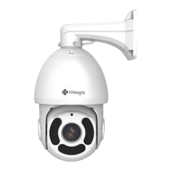
1.3 Hardware Overview (PoE) Speed Dome Network Camera Figure 1-3-1 (PoE) Speed Dome Network Camera Note: AC 24V and PoE are available for power supply. Built-in SD card slot can be seen after removing the 4 screws and open the front panel. - Page 8 12x Mini PoE PTZ Bullet Network Camera Wall Mount: Pedestal Mount: Mini PTZ Bullet: Mini PoE PTZ Bullet: Figure 1-3-2 12x Mini PoE PTZ Bullet Network Camera Note: 1) Reset Button: Press “Reset” button for 5 seconds, then the device will be restored to factory default. 2) Only DC 12V is available for Mini PTZ Bullet power supply.
-
Page 9: System Requirements
1.4 System Requirements Operating System: Windows XP/Vista/7/8/10/Server 2000/Server 2008 CPU: 1.66GHz or higher RAM: 1G or higher Graphic memory: 128MB or more Internet protocol: TCP/IP (IPv4/IPv6) Web Browsers: Internet Explorer 8.0 and above version, Mozilla Firefox, Google Chrome and Safari. -
Page 10: Chapter Ii Network Connection
Chapter II Network Connection 2.1 Setting the Camera over the LAN Connecting the camera to a switch or a router is the most common connection method. The camera must be assigned an IP address that is compatible with its LAN. 2.1.1 Connect the Camera to the PC Directly In this method, only when the computer connected to a camera, it will be able to view the camera. -
Page 11: Dynamic Ip Connection
2.2 Dynamic IP Connection u Connecting the network camera via a router Step1: Connect the network camera to a router; Step2: On the camera, assign a LAN IP address, a Subnet mask and a Gateway; Step3: On the router, set port forwarding. E.g. 80, 8000 and 554 ports. The steps for port forwarding vary depending on different routers. -
Page 12: Chapter Iii Accessing The Network Camera
The camera must be assigned an IP address to be accessible. 3.1 Assigning An IP Address The Network Camera must be assigned an IP address to be accessible. The default IP address of Milesight Network Camera is 192.168.5.190. The default user name is “admin”, and password is “ms1234”. - Page 13 Step3: Select a camera or multiple cameras according to the MAC addresses; Figure 3-1-2 Select single camera Figure 3-1-3 Select multiple cameras...
- Page 14 Step4: Type the User Name and Password (admin/ms1234 for default, please change your password for your device security); Figure 3-1-4 Type the User Name and Password Step5: Change the IP address or other network values, and then click “Modify” button; Figure 3-1-5 Modify...
- Page 15 Step6: Change the IP address successfully; Figure 3-1-6 Change IP address successfully Step7: By double clicking the selected camera or the browser of interested camera, you can access the camera via web browser directly. The Internet Explorer window will pop up. Figure 3-1-7 Login interface More usage of Smart Tools, please refer to the Smart Tools User Manual.
-
Page 16: Assign An Ip Address Via Browser
Click “Advanced”, and then click “IP settings” à “IP address” à “Add” (See Figure 3-1-9). In the pop-up window, enter an IP address that in the same segment with Milesight network camera ( e.g. 192.168.5.61, but please note that this IP address shall not conflict with the IP... - Page 17 Figure 3-1-9 Setting IP Address of Computer Step2: Start the browser. In the address bar, enter the default IP address of the camera: http://192.168.5.190; Step3: Enter the user name and password when the LOGIN page appears; Default user name: admin Default password: ms1234 Figure 3-1-10 Login...
-
Page 18: Accessing From The Web Browser
3-2-2. Please click “Finish” and refresh the browser, then you will see the video. Figure 3-2-2 Finish installation If IE9 or higher version browser is used, it is suggested that the Milesight camera web link should be added as a trusted site. See the instructions as follows: Step1: Start the IE9 or higher version browser, and select “Tools”à... - Page 19 Step2: Select “Security” to “Trusted”; Figure 3-2-4 To trust the control Step3: Enter the IP address of the camera in the blank and click “Add”; Figure 3-2-5 Add the website to the zone Step4: Enter the IP address. After logging on network camera’s web GUI successfully, user is allowed to view live video as follows.
-
Page 20: Accessing From Milesight Vms (Video Management Software)
The interface of Milesight VMS is very easy to use, intuitive, with easy access to the most common activities, such as viewing live video, searching through recordings and exporting videos and snapshots. It's able to be integrated with other devices through ONVIF. -
Page 21: Chapter Iv System Operation Guide
Chapter IV System Operation Guide 4.1 Live Video After logging in the network camera web GUI successfully, you are allowed to view live video as follows. Figure 4-1-1 Live view interface 4.1.1 Operations on Live View Page Table 4-1-1 Description of the buttons Parameter Description Navigation key is used to control the direction. - Page 22 Click to focus near or far of the lens. Lens Initialization, Auxiliary Focus and Auto Iris Lighting For 30s: Click to open/ close the White LED for lighting 30s. 3D Positioning: Click to enable/ disable 3D positioning. One-touch Patrol: Click to carry out the patrol. Auto Home: Click to enable Auto Home.
- Page 23 Click to display images at a window size. Window size Click to display images at a real size. Real size Click to display images at full-screen. Full Screen When recording, the icon will turn red. Recording When an alarm of Smart Event was triggered, the icon appears Alarm When an alarm of Motion Detection was triggered, the icon...
-
Page 24: Positioning
4.1.2 3D Positioning 3D Positioning allows user to use mouse clicking and dragging to control the PTZ. Steps: 1.Click on the toolbar of Live View interface. 2.Operate the 3D positioning function Left click a position of the Live View, the corresponding position will be moved to the center of the Live View. - Page 25 Calling a preset: Select a defined preset form the preset list and click to call the preset. Figure 4-1-3 call a Preset Note: The following presets are predefined with special commands. You can only call them but can’t configure them. For example, preset 037 is the “Self Check”.
- Page 26 Set / Call a patrol A patrol is a memorized series of preset function. It can be configured and called on the patrol setting list. You can customize up to 8 patrols and it can be configured with 48 presets. Before configuring the patrol, you should make sure that the presets you want to add to the patrol have been defined.
- Page 27 Call a patrol: In the PTZ control panel, select a defined patrol from the patrol list, and click to call the patrol, as shown in Figure 4-1-6. Figure 4-1-6 Call a Patrol Note: The three buttons behind the Patrol list means: Play, Set and Delete. Set / Call a pattern A pattern is a memorized series of pan, tilt, zoom and preset functions.
-
Page 28: Playback
Call a pattern: In the PTZ control panel, select a defined pattern from the pattern list, click to call the pattern, as shown in Figure 4-1-8. Figure 4-1-8 Call a Pattern Note: The three button behind the Pattern list means: Play, Record and Delete. When configuring the pattern, pan and tilt are valid but the limit stops and auto flip will be invalid. - Page 29 Step3: Click to play the video files found on this date. The toolbar on the button of playback interface can be used to control playing progress. Figure 4-2-3 Playback Toolbar Table 4-2-1 Description of the buttons Button Operation Play Pause Stop Speed Down Speed Up...
-
Page 30: Local Settings
4.3 Local Settings Record File Length and storage path can be customized in this setting page. Figure 4-3-1 Local Settings 4.4 Basic Settings 4.4.1 Video Stream parameters can be set in this module, adapting to different network environments and demands. Primary Stream Settings Figure 4-4-1 Primary Stream Settings... - Page 31 Secondary Stream Settings Figure 4-4-2 Secondary Stream Settings Tertiary Stream Settings Figure 4-4-3 Tertiary Stream Settings Table 4-4-1 Description of the buttons Parameters Function Introduction Video Codec H.265/H.264/MJPEG are available. Options include 5M(2560*1920)(only for 5MP Mini (PoE) PTZ Bullet and Speed Dome), 4M(2592*1520)(only for 5MP and 4MP Mini (PoE) PTZ Bullet and Speed Dome), 3M(2304*1296), 1080P(1920*1080), 1.3M(1280*960), 720P(1280*720), D1 (704*576).
-
Page 32: Image
Smart Stream mode remarkably reduces the bandwidth and the data storage requirements for network cameras while ensuring the high quality of images, and it is a 10-level adjustable codec. Smart Stream It is optional to turn On/Off Smart Stream mode. Level: Level 1~10 are available to meet your need. - Page 33 Table 4-4-2 Description of the buttons Parameters Function Introduction Power Line Frequency 60HZ flicker for NTSC mode and 50HZ flicker for PAL mode There are several parameters such as Exposure Level, Maximum Exposure Time and IR-CUT Interval, etc, associated with this mode. Night Mode: Show in live view based on Night Mode settings Day Mode: Show in live view based on Day Mode settings Day/Night Mode...
- Page 34 Enhancement Figure 4-4-5 Enhancement Settings Table 4-4-3 Description of the buttons Parameters Function Introduction There is an option to turn On/Off the IR LED. IR Balance Mode IR Balance Mode would avoid the problem of overexposure or darkness, and the IR LED will change according to the actual illumination. To restore white objects and remove color distortion cause by the light of the environment Auto White Balance: This option will automatically enable the White Balance...
- Page 35 Manual Mode: The camera will adjust the brightness according to the value you set, you can set the exposure time from 1~1/100000 s, t he higher the value is, the brighter the image is; Schedule Mode: You can customize the schedule to enable/disable Auto Mode and Manual Mode.
- Page 36 Note: You can customize the schedule to enable/disable the difference White Balance modes. Figure 4-4-6 White Balance schedule settings You can customize the schedule to enable/disable the difference exposure modes. Figure 4-4-7 Exposure mode schedule settings You can customize the schedule to enable/disable BLC/WDR/HLC mode. Figure 4-4-8 BLC/WDR/HLC mode schedule settings WDR/HLC has higher priority than exposure settings at the same time frame.
- Page 37 Figure 4-4-9 Anti-fog Image HLC Image. Figure 4-4-10 HLC Image Day/Night Mode Figure 4-4-11 Day/Night Mode Settings...
- Page 38 Table 4-4-4 Description of the buttons Parameters Function Introduction Exposure Level Level 0~10 are available to meet your need. Minimum Shutter is the same as Maximum Exposure Time. Set the minimum Minimum Shutter Shutter to 1~1/100000s Maximum Shutter is the same as Minimum Exposure Time. Set the maximum Maximum Shutter Shutter to 1~1/100000s IR-CUT Latency...
- Page 39 OSD (On Screen Display) Figure 4-4-12 OSD Settings Table 4-4-5 Description of the buttons Parameters Function Introduction Video Stream Enable to set OSD for primary stream and secondary stream Font Size Smallest/Small/Medium/Large/Largest/Auto are available for title and date Font Color Enable to set different color for title and date Show Video Title Check the checkbox to show video title...
- Page 40 By using Milesight ROI technology, more than 50% of bit rate can be saved and therefore less bandwidth demanded and the storage usage reduced. So according to this, you can set a small bit rate for high resolution.
-
Page 41: Audio
4.4.3 Audio This audio function allows you to hear the sound from the camera or transmit your sound to the camera side. A two-way communication is also possible to be achieved with this feature. Alarm can be triggered when the audio input is above a certain alarm level you set, and configured audio can be played when an alarm occurs. - Page 42 Table 4-4-7 Description of the buttons Parameters Function Introduction Enable Audio Check on the checkbox to enable audio feature. Denoise: Set it as On/Off. When you set the function on, the noise detected can be filtered. Encoding: G711-ULaw, G711-ALaw and AAC LC are available; Audio Input Sample Rate: There are 8KHz/16KHz two options;...
-
Page 43: Network
4.4.4 Network TCP/IP Figure 4-4-16 TCP/IP Settings Table 4-4-8 Description of the buttons Parameters Function Introduction Get IPv4 Address Get an IP address from the DHCP server automatically. Automatically IPv4 Address: It is used to identify a network camera on the network; IPv4 Subnet Mask: It is used for identifying the subnet where the network camera is located;... - Page 44 HTTP Figure 4-4-17 HTTP Settings Table 4-4-9 Description of the buttons Parameters Function Introduction HTTP Enable Start or stop using HTTP. HTTP Port Web GUI login port, the default is 80, the same with ONVIF port. HTTPS Enable Start or stop using HTTPS. HTTPS Port Web GUI login port via HTTPS.
- Page 45 RTSP Figure 4-4-18 RTSP Settings Table 4-4-10 Description of the buttons Parameters Function Introduction RTSP Port The port of RTSP, the default is 554. Playback Port The port of playback, the default is 555. There are Better Compatibility and Better Performance two options. If your RTP Packet camera’s image mess up, please switch this option.
- Page 46 UPnP Universal Plug and Play (UPnP) is a networking architecture that provides compatibility among networking equipment, software and other hardware devices. The UPnP protocol allows devices to connect seamlessly and to simplify the implementation of networks in the home and corporate environments. With the function enabled, you don’t need to configure the port mapping for each port, and the camera is connected to the Wide Area Network via the router.
- Page 47 You need to register an account from a provider. Figure 4-4-20 DDNS Settings You can choose “ddns.milesight.com” as provider for DDNS. After enabling, you can access the device via the URL “http://ddns.milesight.com/MAC address” .
- Page 48 Email Alarm video files can be sent to specific mail account through SMTP server. You must configure the email settings correctly before using it. Figure 4-4-21 SMTP Settings Table 4-4-13 Description of the buttons Parameters Function Introduction User Name The sender's name. It is usually the same as the account name Sender Email Address Email address to send video files attached emails Password...
- Page 49 Alarm video files can be sent to specific FTP server. You must configure the FTP settings correctly before using it. Figure 4-4-22 FTP Settings Table 4-4-14 Description of the buttons Parameters Function Introduction Server Address FTP server address Server Port The port of the FTP server.
- Page 50 VLAN A virtual LAN (VLAN) is any broadcast domain that is partitioned and isolated in a computer network at the data link layer (OSI layer 2). LAN is an abbreviation of local area network. VLANs allow network administrators to group hosts together even if the hosts are not on the same network switch. This can greatly simplify network design and deployment, because VLAN membership can be configured through software.
- Page 51 SNMP You can set the SNMP function to get camera status, parameters and alarm related information and manage the camera remotely when it is connected to the network. Before setting the SNMP, please download the SNMP software and manage to receive the camera information via SNMP port.
-
Page 52: Date&Time
802.1x The IEEE 802.1X standard is supported by the network cameras, and when the feature is enabled, the camera data is secured and user authentication is needed when connecting the camera to the network protected by the IEEE 802.1X. Figure 4-4-26 802.1x Settings 4.4.5 Date &... -
Page 53: Advanced Settings
4.5 Advanced Settings 4.5.1 Alarm Motion Detection Step1: Check the checkbox to enable the motion detection; Step2: Set motion region; Figure 4-5-1 Motion Region Settings Table 4-5-1 Description of the buttons Parameters Function Introduction Enable Motion Check the checkbox to enable Motion Detection function. Detection Normal and Compatible are available for the option. - Page 54 Step4: Set alarm action; Figure 4-5-3 Alarm Action Table 4-5-2 Description of the buttons Parameters Function Introduction Save Into SD Card Save alarm recording files into SD Card. Save Into NAS Save alarm recording files into NAS. Upload Via FTP Upload the recording files via FTP.
- Page 55 Here the Digifort will be taken as an example to introduce the HTTP Notification function. The following are the detail steps of setting for HTTP Notification in Digifort VMS and our cameras. Step1: Enable Alarm; set Motion Region and Detection Schedule; Step2: Confirm the HTTP Notification as Alarm Action, and fill the fields.
- Page 56 So, it's the VMS Software which decides whether we can use this function successfully. Step5: Set alarm settings. Figure 4-5-4 Alarm Settings Table 4-5-3 Description of the buttons Parameters Function Introduction Record Video Sections Six different periods are available(5, 10, 15, 20, 25, 30 sec). Pre-record Reserve the record time before alarm, 0~10 sec.
- Page 57 Figure 4-5-5 Audio Action schedule settings Audio Alarm Enable the Audio before using Audio Alarm function. Figure 4-5-6 Schedule Settings...
- Page 58 Figure 4-5-7 Alarm Settings Please refer to table 4-5-2 and 4-5-3 to get the meaning of items. External Input Figure 4-5-8 Schedule Settings...
- Page 59 Figure 4-5-9 Alarm Settings The meaning of items please refer to table 4-5-2 and 4-5-3, here will not repeat again. Other Alarm Figure 4-5-10 Other Alarm...
- Page 60 Table 4-5-4 Description of the buttons Parameters Function Introduction Network Lost, Tampering and IP Address Conflicted are available Alarm Type Check the checkbox to enable the alarm type you selected Save Into SD Card: Save alarm recording files into SD Card External Output: If the camera equips with External Output, you can enable the action after configuring the trigger duration Play Audio: If the camera equips with Speaker, you can enable the action after...
-
Page 61: Storage
4.5.2 Storage Before you start: To configure record settings, please make sure that you have the network storage device within the network or the SD card inserted in your camera. You can check “Enable Recycle storage”, then it will delete the files when the free disk space reach a certain value. - Page 62 Record Schedule Figure 4-5-14 Record Schedule Table 4-5-6 Description of the buttons Parameters Function Introduction File Sizes: Set record file size, (10-256)M Record Frame Type: All/Key Record Settings (All: Record all the frame Key: Only record I-frame) Schedule Settings Click the Edit button to edit record schedule Note: SD Card or NAS are available.
- Page 63 SD Card Explorer Files will be viewed on this page when they are configured to save into SD card. You can set time schedule every day for recording videos and save video files to your target location. SD card video files are arranged by date. Each day files will be displayed under the corresponding date, from which you can copy and delete files etc.
- Page 64 Snapshot Figure 4-5-16 Snapshot Table 4-5-7 Description of the buttons Parameters Function Introduction Enable Time Snapshot: Check the checkbox to enable the Timing Snapshot function; Interval: Set the snapshots interval, input the number and choose the unit(millisecond, second, minute, hour, day); Save Into SD Card: Save the snapshots into SD card, and choose the file name to add time suffix or overwrite the base file name;...
-
Page 65: Security
4.5.3 Security User Figure 4-4-17 User Settings Table 4-5-8 Description of the buttons Parameters Function Introduction Allow anonymous viewing: Check the checkbox to enable visit from whom Manage Privilege doesn’t have account of the device. User Name: Input user name for creating an account; User Password: Input password for the account;... - Page 66 Access List Figure 4-5-18 Access List Table 4-5-9 Description of the buttons Parameters Function Introduction Maximum number of concurrent streaming: Select the maximum number of General Settings concurrent streaming. Options include Number Limit, 1~9. Rule: Single, Network and Range are available; IP access list IP address: Input the address to get the access to the device.
-
Page 67: Sip
Internet Protocol(IP) networks. This page allows user to configure SIP related parameters. Milesight cameras can be configured as SIP endpoint to call out when alarm triggered; or allow permitted number to call in to check the video if the video IP phone is used. - Page 68 Alarm Phone List Figure 4-5-21 Alarm Phone List Table 4-5-12 Description of the buttons Parameters Function Introduction Phone Number(Call by phone number) & Direct IP Call(Check to accept peer to Phone Type peer IP call). To Phone Number/ Call by phone number or IP address. IP Address Remark Name Display name.
-
Page 69: Smart Event
4.5.5 Smart Event Smart Event uses Milesight Video Content Analysis technology. This technical capability is used in a wide range of domains including entertainment, health-care, retail, automotive, transport, home automation, safety and security. Milesight VCA provides advanced, accurate smart video analysis for Milesight network cameras. - Page 70 Step5: Set alarm settings. Advanced Motion Detection Different from traditional motion detection, Milesight advanced motion detection can filter out “noise” such as lighting changes, natural tree movements, etc. When an object moves in the selected area, it will trigger alarm.
- Page 71 Tamper Detection Tamper Detection is used to detect possible tampering like the camera being unfocused, obstructed or moved. This functionality alerts security staff immediately when any above-mentioned actions occur. Figure 4-5-27 Set Tamper Detection Step1: Set detecting sensitivity; Step2: Set detection schedule; Step3: Set alarm action;...
- Page 72 Step5: Set alarm settings. Note: Milesight allows to set up to four lines at a time. There are three direction modes to choose for triggering alarm. “A→B” means when there is any object crossing the line from the “A” side to the “B” side, the alarm will be triggered.
- Page 73 Human Detection Human detection is used for figuring out whether an object is a human or not. Once human detection is enabled, when there is an object appearing in the detecting area, an ID will show on the frame. If the object is a person, it will mark as “person”.
- Page 74 Figure 4-5-33 Set Counting OSD Step4: Set alarm trigger; Figure 4-5-34 Set Alarm Trigger Step5: Set alarm action; Step6: Set alarm settings. Note: 1) Enable people counting need to enable human detection first; 2) Crossing along the direction of the arrow will record as “In”, opposite is “Out”; 3) Alarm will be triggered when the thresholds reaches to a certain value from 1 to 9999.
- Page 75 Setting Milesight VCA provides the primary setting for the whole VCA functions. “Minimum Size” is to set the whether an object is big enough to trigger other settings. The frame you draw on the screen means that only if the object size is bigger than the frame, the settings for other VCA functions will take effect.
-
Page 76: Ptz
4.5.6 PTZ PTZ Settings provides you to configure the functions and parameters about Pan/Tilt/Zoom. PTZ parameters are mainly include the Basic parameters, Auto Home, Config Clear, PTZ Limit, Initial Position(Mini PTZ Bullet) and Scheduled Tasks. Basic Figure 4-5-36 Basic Settings of PTZ Table 4-5-15 Description of the buttons Parameters Function Introduction... - Page 77 Auto Home Figure 4-5-37 Auto Home Auto Home allows the PTZ camera to return to a predefined Home Position automatically after a period of latency time. Check the checkbox to enable the Auto Home mode. Table 4-5-16 Description of the buttons Parameters Function Introduction Latency Time...
- Page 78 PTZ Limit The PTZ camera can be programmed to move within the configurable PTZ Limits(Left/Right). Figure 4-5-38 PTZ Limit Step1: Check the checkbox to enable the PTZ Limit function. Step2: Choose the limit mode as Manual limit or scanning limit. Manual Limit: When Manual limit stops are set, you can operate the PTZ control panel manually only in limited surveillance area.
- Page 79 Privacy Mask Privacy mask enables to cover certain areas on the live video to prevent certain spots in the surveillance area from being viewed and recorded. The mask area does not move as the lens moves. You can set eight mask areas at most.
- Page 80 Scheduled Tasks You can configure the PTZ camera to perform a certain action automatically in a user-defined time period. Step1: Enter the Scheduled Task Settings interface: Figure 4-5-41 Scheduled Task interface Step2: Check the checkbox to Enable Scheduled Task. Step3: Set the schedule and task details. Step4: Set the Task Recovery Time(from 5 to 720 seconds).
- Page 81 Config Clear Figure 4-5-42 Config Clear Here you can clear PTZ configurations, including all PTZ configurations, Presets, Patrols, Patterns, Auto Homes, PTZ Limits , Initial Position(Mini PTZ Bullet), Privacy Masks and Scheduled Tasks. RS485 Figure 4-5-43 RS485 Here you can clear configure RS485 serial port to control the PTZ of Speed Dome. Protocol, Baudrate, Data Bit, Stop Bit, Parity, Flow Control, PTZ Address should be exactly the same as those of the control device.
-
Page 82: Logs
4.5.7 Logs The logs contain the information about the time and IP that has accessed the camera through web. Figure 4-5-44 Logs Table 4-5-19 Description of the buttons Parameters Function Introduction There are five main log types: All Type, Event, Operation, Information, Main Type Exception. -
Page 83: System
4.6 System All information about the hardware and software of the camera can be checked on this page. Figure 4-6-1 System Information Table 4-6-1 Description of the parameters Parameters Function Introduction Device Name The device name can be customized. It will be seen in file names of video files. Product Model The product model of the camera Hardware Version... -
Page 84: Maintenance
4.7 Maintenance 4.7.1 System Maintenance The software can be upgraded by the following steps: Step1: Browse and select the upgrading file; Step2: Click the “upgrade” button after it prompts upload file successfully. After the system reboots successfully, the update is done. Note: Do not disconnect the power of the device during the update. - Page 85 4.7.2 Auto Reboot Set the date and time to enable Auto Reboot function. The device will restart at the time you set. Figure 4-7-2 Auto Reboot...
-
Page 86: Chapter V Services
Chapter V Services Milesight Technology Co., Ltd provides customers with timely and comprehensive technical support services. End-users can contact your local dealer to obtain technical support. Distributors and resellers can contact directly with Milesight for technical support. Technical Support Mailbox: support@milesight.com Web: http://www.milesight.com...
Need help?
Do you have a question about the UI-5D42-CV and is the answer not in the manual?
Questions and answers