Table of Contents
Advertisement
Quick Links
Advertisement
Table of Contents

Related Manuals for Milesight MS-C3262-FPNA


Summary of Contents for Milesight MS-C3262-FPNA
- Page 1 Quick Start Guide...
-
Page 3: Table Of Contents
5.7 Pro Dome Network Camera ................... 34 6. How to Connect to Alarm Interface ..................38 7. Accessing the Milesight Network Camera ................39 7.1 Assigning An IP Address ....................39 7.1.1 Assigning An IP Address by Using Smart Tools ................ 40... -
Page 4: Package Contents
7.2 Accessing from the Web Browser .................. 49 7.2.1 Access over IE Browser ......................49 Thank you for purchasing Milesight Network Camera. This Guide provides basic instructions on installing and accessing Milesight Network Camera. For more details, please refer to the User Manual. 1. Package Contents... -
Page 5: Cautions
Quick Start Guide package contents listed below. If any item is missing or damaged, please contact the shipper and your Milesight sales representative. Sheet 1-1 Items Quantity Description Milesight Network 1 PC The purchased model Camera Power Adapter 1 PC DC12V, 1.5A MAX (optional for part of devices) -
Page 6: Hardware Overview
Quick Start Guide Web Browsers: Internet Explorer 8.0 and above version, Mozilla Firefox, Google Chrome and Safari. 4. Hardware Overview 4.1 Mini Dome Network Camera Press Button Ethernet Port (PoE) Lens Error LED Indicator Power LED Indicator Micro SD/SDHC/SDXC Card Slot Reset Figure 4-1 Mini Dome Network Camera Note:... -
Page 7: Ir Mini Dome Network Camera
Quick Start Guide 4.2 IR Mini Dome Network Camera Press Button Ethernet Port (PoE) Lens IR LEDs Error LED Indicator Power LED Indicator Light Sensor Micro SD/SDHC/SDXC Card Reset Figure 4-2 IR Mini Dome Network Camera... -
Page 8: Vandal-Proof Mini Dome Network Camera
Quick Start Guide Note: 1) Error LED Indicator: Error LED Indicator is on when the device starts up or runs error. 2) Reset Button: Press “Reset” button for 5 seconds, the device will be restored to factory default. Only PoE is available for power supply. 4.3 Vandal-proof Mini Dome Network Camera... -
Page 9: Wi-Fi Mini Cube Network Camera
Quick Start Guide IR LEDs Light Sensor Screw Microphone Lens Ethernet Port Micro SD/SDHC/SDXC Card Slot (PoE) Reset Power and System LED Indicator Figure 4-3 Vandal-proof Mini Dome Network Camera Note: 1) Error LED Indicator: Error LED Indicator is on when the device starts up or runs error. 2) Reset Button: Press “Reset”... - Page 10 Quick Start Guide Microphone LED Indicators Lens Light Sensor Speaker IR LEDs PIR Sensor or SIP Button Micro SD/SDHC/SDXC Card Slot SIP Button Power Connector Ethernet Port(PoE) Alarm Input/Output WPS/Reset Button Figure 4-4 Wi-Fi Mini Cube Network Camera Note: 1) SIP Button: Trigger alarm via SIP calling. After this button is pressed, the camera will call the SIP Phone.
-
Page 11: Mini Bullet Network Camera
Quick Start Guide DC 12V and PoE are available for power supply; 4.5 Mini Bullet Network Camera IR LEDs Lens Light Sensor Ethernet Port(PoE) Micro SD/SDHC/SDXC Card Slot Reset Button Figure 4-5 Mini Bullet Network Camera... - Page 12 Quick Start Guide Note: 1) Only PoE is available for power supply.
-
Page 13: Remote Focus&Zoom Mini Bullet Network Camera
Quick Start Guide 4.6 Remote Focus&Zoom Mini Bullet Network Camera IR LEDs Lens Light Sensor DC 12V Ethernet Port(PoE) Reset Button Micro SD/SDHC/SDXC Card Slot Figure 4-6 Remote Focus&Zoom Mini Bullet Network Camera Note:... -
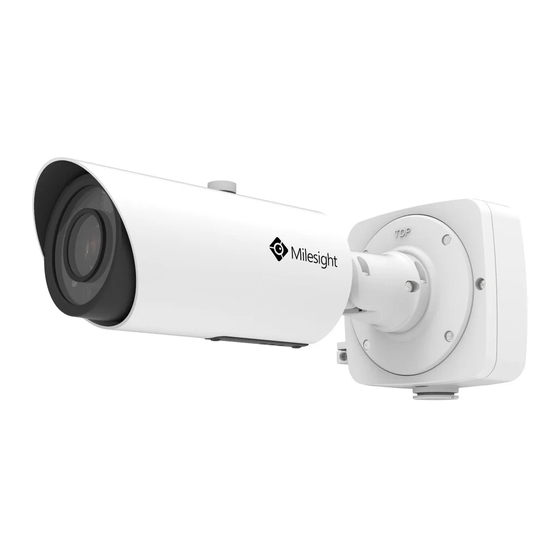
Page 14: Pro Bullet Network Camera
Quick Start Guide 1) DC 12V and PoE are available for power supply. 4.7 Pro Bullet Network Camera Reset Micro SD/SDHC/SDXC Card Slot Light Sensor Breathe IR LEDs Alarm/Audio Lens Light Sensor Ethernet Port (POE) Ethernet Port (PoE) Power Connector Figure 4-7 Pro Bullet Network Camera Note:... -
Page 15: Pro Dome Network Camera
Quick Start Guide DC 12V and PoE are available for power supply. 4.8 Pro Dome Network Camera Lens Light Sensor IR LEDs Reset Micro SD/SDHC/SDXC Card Slot Figure 4-8 Pro Dome Network Camera... - Page 16 Quick Start Guide Note: 1) There are two versions for Pro Dome: Standard and Multiple Interface, the interface’s pictures are as following; 2) Multiple Interface adopts the external interface “Audio In” instead of the Microphone built-in; DC 12V Ethernet Port(PoE) WAFER Contact Figure 4-9 Pro Dome Network Camera(Standard Interface)
- Page 17 Quick Start Guide Ethernet Port External Interface Audio In (PoE) DC 12V Audio Out Figure 4-10 Pro Dome Network Camera(Multiple Interface)
-
Page 18: Hardware Installation
Quick Start Guide 5. Hardware Installation 5.1 Mini Dome Network Camera Step1: Remove the dome cover; Press Button Step2: Secure the screws;... - Page 19 Quick Start Guide Step3: Connect and route an Ethernet cable through the ceiling or wall; Step4: Adjust the lens angle and focus;...
- Page 20 Quick Start Guide Pan Range:+15° Tilt Range:0-90° 20° Step5: Attach the dome cover;...
-
Page 21: Ir Mini Dome Network Camera
Quick Start Guide 5.2 IR Mini Dome Network Camera Step1: Remove the dome cover;... - Page 22 Quick Start Guide Step2: Secure the screws; Step3: Connect and route an Ethernet cable through the ceiling or wall;...
- Page 23 Quick Start Guide Step4: Attach the dome cover;...
- Page 24 Quick Start Guide Step5: Adjust the lens angle and focus; Pan Range:+17.5° Tilt Range:20-60° 20°...
-
Page 25: Vandal-Proof Mini Dome Network Camera
Quick Start Guide 5.3 Vandal-proof Mini Dome Network Camera Step1: Remove the dome cover; Step2: Secure the screws;... - Page 26 Quick Start Guide Step3: Connect and route an Ethernet cable through the ceiling or wall; Step4: Loosen the screw and adjust the lens angle and focus;...
- Page 27 Quick Start Guide Step5: Attach the dome cover;...
-
Page 28: Wi-Fi Mini Cube Network Camera
Quick Start Guide 5.4 Wi-Fi Mini Cube Network Camera Step1: Mount the cube camera to the ceiling or wall, or place the cube camera horizontally;... - Page 29 Quick Start Guide Step2: Connect the power adapter and Ethernet cable; Power Cable Ethernet Cable Step3: Adjust the shooting direction; 90° 360°...
-
Page 30: Mini Bullet Network Camera
Quick Start Guide 5.5 Mini Bullet Network Camera Step1: Loosen the waterproof connector, and then remove the rubber seal, and the waterproof connector; Step2: Loosen and open the rear cover; Step3: Install a Micro SD/SDHC/SDXC card, connect an Ethernet cable and pass it through the rubber seal.;... - Page 31 Quick Start Guide Step6: Pass the Ethernet cable through the center of the mount bracket, put the bracket and camera together, rotate the bracket and fasten the bracket using screws; Step7: Mount the camera to the ceiling or wall; Step8: Adjust the shooting direction;...
- Page 32 Quick Start Guide Note: 1) The upper cover of the mini bullet Network Camera could only be moved forward for 5mm at most to ensure better field of view.
-
Page 33: Pro Bullet Network Camera
Quick Start Guide 5.6 Pro Bullet Network Camera Step1: Fix a sticker in the position where you want to install your camera; 150mm... - Page 34 Quick Start Guide Step2: Pass the Ethernet cable through the rear cover and fasten the rear cover to the ceiling or wall;...
- Page 35 Quick Start Guide Step3: Connect an Ethernet cable and hook for your camera with a hang rope; Step4: Install and tighten the rear cover and fasten the bracket to the camera using 4 plum flower head screws; Step5: Adjust the shooting direction;...
-
Page 36: Pro Dome Network Camera
Quick Start Guide 90° 360° 360° 5.7 Pro Dome Network Camera Step1: Fix a sticker in the position where you want to install your camera. Install the supplied bracket on the ceiling or wall, secure the screws;... - Page 37 Quick Start Guide Step2: Connect an Ethernet and pass it through the rubber seal; Step3: Rotate the camera unit according to the direction shown in the picture, and then attach the...
- Page 38 Quick Start Guide camera unit to the bracket with the supplied screws; Step4: Connect and route an Ethernet cable and the power source through the ceiling or wall, then attach the camera unit to the bracket;...
- Page 39 Quick Start Guide Step5: Loosen the camera head fixing screw. Adjust the camera to turn the lens in the desired direction. Tighten the camera head fixing screw to fix the camera; Step6: Attach the dome cover;...
-
Page 40: How To Connect To Alarm Interface
Quick Start Guide The raised place should align to the hole. 6. How to Connect to Alarm Interface External interface of camera is as the following, you can refer to the picture to install the external alarm device: The raised place should align to the hole. -
Page 41: Accessing The Milesight Network Camera
The camera must be assigned an IP address to be accessible. 7.1 Assigning An IP Address The Network Camera must be assigned an IP address to be accessible. The default IP address of Milesight Network Camera is 192.168.5.190. The default user name is “admin”, and password is “ms1234”. -
Page 42: Assigning An Ip Address By Using Smart Tools
LAN of your computer. 7.1.1 Assigning An IP Address by Using Smart Tools Smart Tools is a software tool which can automatically detect multiple online Milesight network cameras connected in the LAN, set IP addresses, and manage firmware upgrades. It’s recommended when assigning IP addresses for multiple cameras. - Page 43 Quick Start Guide Figure 7-2 Select single camera...
- Page 44 Quick Start Guide Figure 7-3 Select multiple cameras Step4: Type the User Name and Password (if they are not the default value.);...
- Page 45 Quick Start Guide Figure 7-4 Step5: Change the IP address or other network values, and then click “Modify” button;...
- Page 46 Quick Start Guide Figure 7-5 Step6: Change the IP address successfully;...
- Page 47 Quick Start Guide Figure 7-6 Change IP address successfully Step7: By double clicking the selected camera, you can access the camera via web browser directly. The Internet Explorer window will pop up. Figure 7-7...
- Page 48 Click “Advanced”, and then click “IP settings”→ “IP address”→ “Add” (See Figure 7-9). In the pop-up window, enter an IP address that in the same segment with Milesight Network Camera ( e.g. 192.168.5.61, but please note that this IP address shall not conflict with the...
- Page 49 Quick Start Guide Figure 7-9 Step2: Start the browser. In the address bar, enter the default IP address of the camera:...
- Page 50 Quick Start Guide http://192.168.5.190; Step3: Enter the user name and password when the LOGIN page appears; Default user name: admin Default password: ms1234 Figure 7-10 Step4: After login, please select “Configuration”→“Basic Settings”→ “Network”→ “TCP/IP”. The Network Settings page appears (Shown as following Figure);...
- Page 51 Quick Start Guide Figure 7-11 Step5: Change the IP address or other network values. Then click “Save” button; 7.2 Accessing from the Web Step6: The change of default IP address is completed. Browser The camera can be used with the most standard operating systems and browsers. The recommended browsers are Internet Explorer, Firefox, Chrome, Safari.
- Page 52 Figure7-12. Please click “Finish” and refresh the browser, then you will see the video. Figure 7-13 If IE9 or higher version browser is used, it is suggested that the Milesight camera web link should be added as a trusted site. See the instructions as follows:...
- Page 53 Quick Start Guide Figure7-14 Step2: Select “Security” to “Trusted”; Figure 7-15 Step3: Enter the IP address of the camera in the blank and click “Add”;...
- Page 54 Quick Start Guide Figure 7-16 Step4: Enter the IP address. After logging on Network Camera’s web GUI successfully, user is allowed to view live video as follows. Figure 7-17...
- Page 56 Quick Start Guide...
Need help?
Do you have a question about the MS-C3262-FPNA and is the answer not in the manual?
Questions and answers