Table of Contents
Advertisement
Quick Links
Advertisement
Table of Contents

Related Manuals for Milesight MS-C5364-PB


Summary of Contents for Milesight MS-C5364-PB
- Page 1 Network Camera User Manual V7.19...
- Page 2 Thank you for purchasing our product. If there is any questions or requests, please do not hesitate to contact your dealer. This manual is applicable to the Milesight H.265 Network Camera, series shown as follows, except where otherwise indicated. Milesight H.265 Network Camera...
- Page 3 Milesight Technology Co., Ltd(Hereinafter referred to as Milesight). Milesight reserves the right to change this manual and the specifications without prior notice. The latest specifications and user documentation for all Milesight products are available on our official website www.milesight.com...
- Page 4 Source with DC 12V or PoE Please make sure the plug is firmly inserted into the power socket When the product is installed on a wall or ceiling, the device should be firmly fixed If the product does not work properly, please contact your dealer. Never attempt to disassemble the camera by yourself Cautions ...
-
Page 5: Table Of Contents
3.1.2 Assign An IP Address via Browser ................23 3.2 Accessing from the Web Browser..................26 3.2.1 Access with Plugin ....................... 26 3.2.2 Access without Plugin ....................28 3.3 Accessing from Milesight VMS (Video Management Software)........... 28 Chapter IV System Operation Guide....................30 4.1 Live Video..........................30 4.2 Playback..........................32 4.3 Local Settings......................... - Page 6 4.7 System..........................111 4.8 Maintenance........................112 4.8.1 System Maintenance....................112 4.8.2 Auto Reboot.......................114 Chapter V Services..........................114...
-
Page 7: Chapter I Product Description
Chapter I Product Description 1.1 Product Overview Milesight provides a consistent range of cost-effective and reliable network cameras to fully meet your requirements. Based on embedded Linux operating system, Milesight network cameras could be easily accessed and managed either locally or remotely with great reliability. -
Page 8: Hardware Overview
1.3 Hardware Overview 1. IR Mini Dome Network Camera Ethernet Port (PoE) Press Button Figure 1-3-2 IR Mini Dome Network Camera Note: 1) Error LED Indicator: Error LED Indicator is on when the device starts up or runs error. 2) Reset Button: Press “Reset” button for 5 seconds, then the device will be restored to factory default. - Page 9 2. Vandal-proof Mini Dome Network Camera IR LEDs Light Sensor Microphone Screw Lens microSD/SDHC/SDXC Ethernet Port (PoE) Card Slot Reset Power and System LED Indicator Figure 1-3-3 Vandal-proof Mini Dome Network Camera Note: 1) Error LED Indicator: Error LED Indicator is on when the device starts up or runs error. 2) Reset Button: Press “Reset”...
- Page 10 3. Weather-proof Mini Dome Network Camera Figure 1-3-4 Weather-proof Mini Dome Network Camera Note: 1) Reset Button: Press “Reset” button for 5 seconds, then the device will be restored to factory default. 2) Only PoE is available for power supply.
- Page 11 4. AF Motorized Mini Dome Network Camera Figure 1-3-5 AF Motorized Mini Dome Network Camera Note: 1) Reset Button: Press “Reset” button for 5 seconds, then the device will be restored to factory default. 2) DC 12V and PoE are available for power supply.
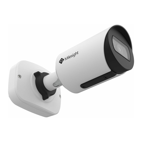
- Page 12 5. Mini Bullet Network Camera Figure 1-3-6 Mini Bullet Network Camera Note: 1) DC 12V(Only for Multi-interface Version) and PoE are available for power supply. 2) Reset Button: Press “Reset” button for 5 seconds, then the device will be restored to factory default.
- Page 13 6. Vandal-proof Mini Bullet Network Camera Figure 1-3-7 Vandal-proof Mini Bullet Network Camera Note: 1) Only PoE is available for power supply. 2) Reset Button: Press “Reset” button for 5 seconds, then the device will be restored to factory default.
- Page 14 7. (Vandal-proof) Motorized Mini Bullet Network Camera Ethernet Port (PoE) Figure 1-3-8 (Vandal-proof) Motorized Mini Bullet Network Camera Note: 3) DC 12V and PoE are available for power supply. 4) Reset Button: Press “Reset” button for 5 seconds, then the device will be restored to factory default.
- Page 15 8. 180°Panoramic Mini Bullet Network Camera Note: 1) PoE is available for power supply. 2) Reset Button: Press “Reset” button for 5 seconds, then the device will be restored to factory default.
- Page 16 9. 180°Panoramic Mini Dome Network Camera Note: 3) PoE is available for power supply. 4) Reset Button: Press “Reset” button for 5 seconds, then the device will be restored to factory default.
- Page 17 10. (AI) (12X AF) Motorized Pro Bullet Network Camera microSD/SDHC/SDXC Card Slot Reset PTFE Membrane IR LEDs Lens Light Sensor Figure 1-3-9 (12x AF) Motorized Pro Bullet Network Camera Note: 5) DC 12V and PoE are available for power supply. 6) Reset Button: Press “Reset”...
- Page 18 Ethernet Port (PoE) Alarm/Audio DC 12V Figure 1-3-10 Motorized Pro Bullet Network Camera(Version A) Audio In/Out Ethernet Port (PoE) Alarm In/Out DC 12V Figure 1-3-11 Motorized Pro Bullet Network Camera(Version B)
- Page 19 11. (AI) Motorized Pro Dome Network Camera Microphone Lens Light Sensor IR LEDs Reset microSD/SDHC/SDXC Card Slot Figure 1-3-12 Motorized Pro Dome Network Camera Note: 1) Reset Button: Press “Reset” button for 5 seconds, then the device will be restored to factory default.
- Page 20 DC 12V Alarm In/Out & Audio Out/DC 12V Ethernet Port (PoE) Water-proof Connector Figure 1-3-13 Motorized Pro Dome Network Camera multiple interface Here is one equipped cable for multiple interface usage: Ethernet Port DC 12V (PoE) Alarm In/Out Audio Out Alarm In/Out &...
- Page 21 12. (LPR) (ABF) Pro Box Network Camera Figure 1-3-15 (ABF) Pro Box Network Camera Note: Reset Button: Press “Reset” button for 5 seconds, then the device will be restored to factory default. DC 12V and PoE are available for power supply.
-
Page 22: How To Connect To Alarm Interface
1.4 How to Connect to Alarm Interface External interface of camera is as the following, you can refer to the picture to install the external alarm device: PIN1: Alarm Output NC/NO 24V DC 1A PIN2: Alarm Output NC/NO 24V DC 1A PIN3: Alarm Input NC/NO ≤12V PIN4: Alarm Input NC/NO ≤12V 1.5 How to Connect the Water-proof Connector... -
Page 23: System Requirements
1.6 System Requirements Operating System: Windows XP/Vista/7/8/10/Server 2000/Server 2008 CPU: 1.66GHz or higher RAM: 1G or higher Graphic memory: 128MB or more Internet protocol: TCP/IP (IPv4/IPv6) Web Browsers: Internet Explorer 8.0 and above version, Mozilla Firefox, Google Chrome and Safari. -
Page 24: Chapter Ii Network Connection
Chapter II Network Connection 2.1 Setting the Camera over the LAN Connecting the camera to a switch or a router is the most common connection method. The camera must be assigned an IP address that is compatible with its LAN. 2.1.1 Connect the Camera to the PC Directly In this method, only the computer connected to the camera will be able to view the camera. - Page 25 Step5: Configure the DDNS settings in the setting interface of the router; Step6: Visit the camera via the domain name. Figure 2-2 Connect the network camera via a router using dynamic IP...
-
Page 26: Chapter Iii Accessing The Network Camera
Step2: Start Smart Tools, click the IPC Tools page, then enter the device information, such as IP address, MAC address, Status, Port number, Netmask, and Gateway, then all related Milesight network cameras in the same network that will be displayed. Details are shown as shown below;... - Page 27 Step3: Select a camera or multiple cameras according to the MAC addresses; Select single camera Select multiple cameras Step4: If the selected camera shows "Active" in the status bar, you can directly type the User Name and Password (Camera with version lower than 4x.7.0.69 is using admin/ms1234 by default), change the IP address or other network values, and then click “Modify”...
- Page 28 If the selected camera shows "Inactive" in the status bar(Camera with version V4x.7.0.69 or above), click to set the password when using it for the first time. You can also set the security questions when activating the camera in case that you forget the password(You can reset the password by answering three security questions correctly).
-
Page 29: Assign An Ip Address Via Browser
Step5: Change the IP address successfully; Step6: By double clicking the selected camera or the browser of interested camera, you can access the camera via web browser directly. The Internet Explorer window will pop up. More usage of Smart Tools, please refer to the Smart Tools User Manual. 3.1.2 Assign An IP Address via Browser If the network segment of the computer and that of the camera are different, please follow the... - Page 30 Click “Advanced”, and then click “IP settings” “IP address” “Add” (See Figure 3-1-9). In the pop-up window, enter an IP address that in the same segment with Milesight network camera ( e.g. 192.168.5.61, but please note that this IP address shall not conflict with the IP address on the existing network);...
- Page 31 Step3: If the camera’s firmware version is lower than V4x.7.0.69, it will directly display the login page, enter the user name and password when the LOGIN page appears; Default user name: admin Default password: ms1234 If the camera’s firmware version is V4x.7.0.69 or above, you need to set the password first when using it for the first time.
-
Page 32: Accessing From The Web Browser
Step5: Change the IP address or other network values. Then click “Save” button; Step6: The change of default IP address is completed. 3.2 Accessing from the Web Browser The camera can be used with the most standard operating systems and browsers. The recommended browsers are Internet Explorer, Firefox, Chrome, Microsoft Edge, Safari. - Page 33 If IE9 or higher version browser is used, it is suggested that the Milesight camera web link should be added as a trusted site. See the instructions as follows: Step1: Start the IE9 or higher version browser, and select “Tools” “Internet Options”;...
-
Page 34: Access Without Plugin
As browser security becomes more and more important, some browsers don’t support installing plugin. In order to normally preview the video on the browser, Milesight upgraded the camera to support Plugin-Free Mode. In Plugin-Free Mode, you can preview the video on the browser without plugin. -
Page 35: Accessing From Milesight Vms (Video Management Software)
The interface of Milesight VMS is very easy to use, intuitive, with easy access to the most common activities, such as viewing live video, searching through recordings and exporting videos and snapshots. -
Page 36: Chapter Iv System Operation Guide
Chapter IV System Operation Guide 4.1 Live Video After logging in the network camera web GUI successfully, user is allowed to view live video as follows. Table 4-1-1 Description of the buttons Parameter Description Brightness: Adjust the Brightness of the scene Contrast: Adjust the color and light contrast Saturation: Adjust the Saturation of the image.Higher Saturation makes colors appear more "pure"... - Page 37 (Chrome version 44 or below); need to install the component to display the view; MJPEG: Support to display the view on Firefox, Safari, Chrome (Chrome version 45 or above); (NOTE: IE choose Web Components mode for default, in this case, it will not show the options) TCP: More reliable connection;...
-
Page 38: Playback
Adjust iris automatically if check this box ( Only work when your camera is equipped with P-Iris) Start/Stop live view Click to capture the current image and save to the configured path. The default path is Capture C:VMS\+-1\ IMAGE-MANUAL Click to start recording video and save to the configured path. - Page 39 Step2: Click the date button, choose the date when date window pops up; Note: 1) The date with bright red means current date; one with a dark red number and white background means weekend day; one with a dark red number and blue background means that the date is selected now.
-
Page 40: Local Settings
Time Narrow/Expand Start/Stop Recording Snapshot Zoom On/Off Full Screen Note: 1) Drag the progress bar with the mouse to locate the exact playback point. You can also input the time and click to locate the playback point in the Set Playback Time filed. You can also click to zoom out/in the progress bar. - Page 41 Record Stream Type (General) Record Stream Type (Event) Secondary Stream Settings Tertiary Stream Settings Table 4-4-1 Description of the buttons Parameters Function Introduction...
- Page 42 General & Event are available only for Primary Stream. General refers to continuous record video, while Event includes events that can trigger alarms, such as Motion, Exception, LPR and so on. Record Stream Type This item can separately set different bit rate and frame rate for different Recording Stream Types.
-
Page 43: Image
Set the I-frame interval to 1~120, 50 for the default. This item is optional only if you I-frame Interval select the H.265/H.264. The number must be a multiple of the number of frames. this item is optional only if you selected the Low/Medium/High/Higher are available, JPEG Quality MJPEG... - Page 44 This is the sensitivity for switching Day Mode to Night Mode. When IR Light Day To Night Value Sensor Current Value is lower than this value, it will switch Day Mode to Night Mode This is the sensitivity for switching Night Mode to Day Mode. When IR Light Night To Day Value Sensor Current Value is higher than this value, it will switch Night Mode to Day Mode...
- Page 45 Enhancement Table 4-4-3 Description of the buttons Parameters Function Introduction There is an option to turn On/Off the IR LED. IR Balance Mode IR Balance Mode would avoid the problem of overexposure and darkness, and the IR LED will change according to the actual illumination. To restore white objects, removed color distortion caused by the light of the environment Auto White Balance: This option will automatically enable the White...
- Page 46 the value is, the brighter the image is; Schedule Mode: You can customize the schedule to enable/disable Auto Mode and Manual Mode. Single Mode Set single mode for BLC/WDR/HLC. Support BLC/WDR/HLC on Day Enhancement Mode/Night Enhancement Day/Night Mode Mode separately. Schedule Mode Set schedule mode for BLC/WDR/HLC.
- Page 47 2) You can customize the schedule to enable/disable the difference exposure modes. 3) You can customize the schedule to enable/disable BLC/WDR/HLC mode. 4) WDR/HLC has higher priority than exposure settings at the same time frame. 5) Defog Image.
- Page 48 6) HLC Image. Day/Night Mode Table 4-4-4 Description of the buttons Parameters Function Introduction...
- Page 49 Exposure Level Level 0~10 are available to meet your need Minimum Shutter is the same as Maximum Exposure Time. Set the minimum Minimum Shutter Shutter to 1~1/100000 Maximum Shutter is the same as Minimum Exposure Time. Set the maximum Maximum Shutter Shutter to 1~1/100000 IR-CUT Latency The interval time of switching one mode to another...
- Page 50 Note: Background color can not be the same with font color Show Video Title Check the checkbox to show video title Video Title Customize the OSD content Text Position OSD display position on the image Show Timestamp Check the checkbox to display date on the image Date Position Date display position on the image Date Format...
- Page 51 By using Milesight ROI technology, more than 50% of bit rate can be saved and therefore less bandwidth demanded and the storage usage reduced. So according to this, you can set a small bit rate for high resolution.
-
Page 52: Audio
4.4.3 Audio This audio function allows you to hear the sound from the camera or transmit your sound to the camera side. A two-way communication is also possible to be achieved with this feature. Alarm can be triggered when the audio input is above a certain alarm level you set, and configured audio can be played when an alarm occurs. -
Page 53: Network
Denoise: Set it as On/Off. When you set the function on, the noise detected can be filtered Encoding: G.711-ULaw, G.711-ALaw, AAC LC, G.722 and G.726 are available Audio Bit Rate: The function is available only for AAC LC, and supports up to Audio Input 256kbps Sample Rate: 8KHz, 16KHz, 32KHz, 44.1KHz, and 48KHz are available... - Page 54 Table 4-4-9 Description of the buttons Parameters Function Introduction Get IPv4 Address Get an IP address from the DHCP server automatically Automatically IPv4 Address: An address that used to identify a network camera on the network IPv4 Subnet Mask: It is used to identify the subnet where the network camera is located IPv4 Default Gateway: The default router address Preferred DNS Server: The DNS Server translates the domain name to IP...
- Page 55 Table 4-4-10 Description of the buttons Parameters Function Introduction HTTP Enable Start or stop using HTTP HTTP Port Web GUI login port, the default is 80, the same with ONVIF port HTTPS Enable Start or stop using HTTPS HTTPS Port Web GUI login port via HTTPS, the default is 443 HTTP Settings Upload and set the SSL certificate .
- Page 56 RTSP Table 4-4-11 Description of the buttons Parameters Function Introduction RTSP Port The port of RTSP, the default is 554 Playback Port The port of playback, the default is 555 There are Better Compatibility and Better Performance two options, if your RTP Packet camera’s image mess up, please switch this option Multicast Group...
- Page 57 UPnP Universal Plug and Play (UPnP) is a networking architecture that provides compatibility among networking equipment, software and other hardware devices. The UPnP protocol allows devices to connect seamlessly and to simplify the implementation of networks in the home and corporate environments.
- Page 58 Host name DDNS name enabled in the account Note: 1)Please do the Port Forwarding of HTTP Port and RTSP Port before you use Milesight DDNS. 2)Make sure that the internal and the external port number of RTSP are the same. Email Alarm video files can be sent to specific mail account through SMTP server.
- Page 59 Table 4-4-14 Description of the buttons Parameters Function Introduction Enable Check the checkbox to enable Email function User Name The sender's name. It is usually the same as the account name Sender Email Address Email address to send video files attached emails Password The password of the sender SMTP Server...
- Page 60 Table 4-4-15 Description of the buttons Parameters Function Introduction Server Address FTP server address Server Port The port of the FTP server. Generally it is 21 User Name User name used to log in to the FTP sever Password User password Storage Path where video and image will be uploaded to the FTP server.
- Page 61 Timing Snapshot File Default(YYYY-MM-DD) /MM-DD-YYYY/ DD-MM-YYYY/ Add prefix/ Overwrite with Name the base file name are available. Note: Parent Directory will be under Root Directory, and Child Directory will be under Parent Directory. VLAN A virtual LAN (VLAN) is any broadcast domain that is partitioned and isolated in a computer network at the data link layer (OSI layer 2).
- Page 62 You can set the SNMP function to get camera status, parameters and alarm related information and manage the camera remotely when it is connected to the network. Before setting the SNMP, please download the SNMP software and manage to receive the camera information via SNMP port.
- Page 63 Note: 1) The settings of SNMP software should be the same as the settings you configure here; 2) A reboot is required for the settings to take effect. 802.1x The IEEE 802.1X standard is supported by the network cameras, and when the feature is enabled, the camera data is secured and user authentication is needed when connecting the camera to the network protected by the IEEE 802.1X.
-
Page 64: Date&Time
24hrs to activate the account for using live function. 2) For RTMP, since G.711 is not available for YouTube, so you can only play video from Milesight Network Camera with H.264 video coding and AAC audio coding on YouTube. -
Page 65: Advanced Settings
Set the System Time Table 4-4-17 Description of the buttons Parameters Function Introduction Time Zone Choose a time zone for your location Daylight Saving time Enable the daylight saving time NTP server Input the address of NTP server NTP Sync Regularly update your time according to the interval time Manual Set the system time manually... - Page 66 Detection Sensitivity Sensitivity level, 1~10 Normal and Compatible are available for the option. If the setting of motion Onvif Motion region of the third-party software is different from ours, please set this option to ActiveCells Settings Compatible. Select All Click the button, the motion in the area will be detected Clear All Click the button, the area drawn before will be removed Step3: Set motion detection schedule;...
- Page 67 If the camera equips with External Output, you can enable the action after External Output configuring the trigger duration If the camera equips with Speaker, you can enable the action after configuring the Play Audio audio speaker If the camera equips with Buzzer, you can check the checkbox to enable the Play Buzzer function.
- Page 68 Example: http://192.168.8.75:8601/Interface/Cameras/MotionDetection/Notify?Camera=annie, this URL format is exactly supported by Digifort VMS, so we can set as above to our cameras and get it work well. Step3: choose use motion detection by external notification; Step4: If successful, you can see the device icon turns yellow in the Surveillance when the camera is under Motion Detection Alarm;...
- Page 69 Table 4-5-3 Description of the buttons Parameters Function Introduction Record Video Sections Six different periods are available(5, 10, 15, 20, 25, 30 sec) Snapshot The number of snapshot, 1~5 Snapshot Interval This cannot be edited unless you choose more than 1 to Snapshot External Output Action Length of time an alarm lasts, this cannot be edited unless you enable the Time...
- Page 71 The meaning of items please refer to table 4-5-2 and 4-5-3, here will not repeat again. External Input...
- Page 72 The meaning of items please refer to table 4-5-2 and 4-5-3, here will not repeat again. External Output Please set the Normal Status firstly, when the Current Status is different with Normal Status, it will lead to the alarm. Exception...
- Page 73 Table 4-5-4 Description of the buttons Parameters Function Introduction Network Disconnected, IP Address Conflicted, Record Failed, SD Card Full, SD Alarm Type Card Uninitialized, SD Card Error and No SD Card are available Check the checkbox to enable the alarm type you selected Save Into Storage: Save alarm recording files into SD Card Upload Via Email: Upload alarm recording files via email.
-
Page 74: Storage
Record Video Sections: Six different periods are available(5, 10, 15, 20, 25, 30 sec) Snapshot: The number of snapshot, 1~5 Snapshot Interval: This cannot be edited unless you choose more than 1 to Snapshot External Output Action Time: Length of time an alarm lasts, this cannot be edited Alarm Setting unless when you enable the External Output on the Alarm Action firstly Audio Action Settings: Set the audio schedule to trigger different audio files and... - Page 75 Table 4-5-6 Description of the buttons Parameters Function Introduction Server Address IP address of NAS server File Path Input the NAS file path, e.g. “\path”. NFS and SMB/CIFS are available. And you can set the user name and password to Mounting Type guarantee the security if SMB/CIFS is selected Note:...
- Page 76 Schedule Settings Click the Edit button to edit record schedule Note: SD Card or NAS are available. Snapshot Settings Table 4-5-8 Description of the buttons Parameters Function Introduction Enable Time Snapshot: Check the checkbox to enable the Timing Snapshot function Interval: Set the snapshots interval, input the number and choose the unit(millisecond, second, minute, hour, day) Save Into Storage: Save the snapshots into SD card or NAS, and choose the file...
-
Page 77: Security
Files will be seen on this page when they are configured to save into SD card or NAS. You can set time schedule every day for recording videos and save video files to your desired location. (Note: Files are visible once SD card is inserted. Don’t insert or pull out SD card when power on.) Video files are arranged by date. - Page 78 Table 4-5-9 Description of the buttons Parameters Function Introduction Allow anonymous viewing: Check the checkbox to enable visit from whom Manage Privilege doesn’t have account of the device Click “Edit” button to set three security questions for your camera. In case that you forget the password, you can click “Forget Password”...
- Page 79 Click “Add” button, it will display Account Management page. You can add an account to the camera by entering Admin Password, User Level, User Name, New Password, Confirm, and edit user privilege by clicking . The added account will be displayed in the account list. Admin Password: You can add an account only after you enter the correct admin password.
- Page 80 Table 4-5-10 Description of the buttons Parameters Function Introduction Maximum number of concurrent streaming: Select the maximum number of General Settings concurrent streaming. Options include No Limit, 1~9 Rule: Single, Network and Range are available IP access list IP address: Input the address to get the access to the device Enable access list Able to access or restrict access for some IP address filtering...
-
Page 81: Sip
Internet Protocol(IP) networks. This page allows user to configure SIP related parameters. Milesight cameras can be configured as SIP endpoint to call out when alarm triggered; or allow permitted number to call in to check the video if the video IP phone is used. - Page 82 Table 4-5-12 Description of the buttons Parameters Function Introduction Unregistered/ SIP registration status. Display “Unregistered” or “Registered” Registered Enable Start or stop using SIP Choose to use Enable mode or Disable mode. Enable mode means to use SIP with Register Mode register account.
-
Page 83: Vca
Including the phone number or IP address on the white list IP Address Enable White List When enabled, only the designated phone number or IP address can visit Number Filter 4.5.5 VCA Smart Event uses Milesight Video Content Analysis technology. This technical capability is used in a... - Page 84 Milesight VCA provides advanced, accurate smart video analysis for Milesight network cameras. It enhances the performance of network cameras through 10 detection modes which are divided into basic function and advanced function, enabling a comprehensive surveillance system and quicker response of cameras to different monitoring scenes.
- Page 85 Advanced Motion Detection Different from traditional motion detection, Milesight advanced motion detection can filter out “noise” such as lighting changes, natural tree movements, etc. When an object moves in the selected area, it will trigger alarm.
- Page 86 Step1: Set detecting sensitivity; Step2: Set Ignore Short-Lived Motion time. If you set the time, when the moving duration of an object is within the setting time, it will not trigger alarm; Step3: Set advanced motion detection region; Step4: Set detection schedule; Step5: Set alarm action;...
- Page 87 above-mentioned actions occur. Step1: Set detecting sensitivity; Step2: Set detection schedule; Step3: Set alarm action; Step4: Set alarm settings. If you enable External Output and choose Constant External Output Action Time, when possible tampering is detected, External Output Action alarm time will be always constant till the alarm is released.
- Page 88 Settings steps are shown as follows: Step1: Choose a line number; Step2: Enable Line Crossing Detection and define its direction; Step3: Set detecting sensitivity; Step4: Draw detection lines; Step5: Set detection schedule; Step6: Set alarm action; Step7: Set alarm settings. If you enable External Output and choose Constant External Output Action Time, when objects cross a defined virtual line, External Output Action alarm time will be always constant till the alarm is released.
- Page 89 Note: Milesight allows to set up to four lines at a time. There are three direction modes to choose for triggering alarm. “A→B” means when there is any object crossing the line from the “A” side to the “B” side, the alarm will be triggered. “B→A” vice versa. “A ↔ B” means that the alarm will be triggered when objects cross line from either side.
- Page 90 Note: After setting minimum loitering time from 3s to 1800s, any objects loitering in the selected area over the minimum loitering time will trigger the alarm. Human Detection Human detection is used for figuring out whether an object is a human or not. Once human detection is enabled, when there is an object appearing in the detecting area, an ID will show on the frame.
- Page 91 People Counting People counting is able to count that how many people enter or exit during the setting period. Step1: Set detection line; Step2: Set detection schedule; Step3: Set counting OSD; The OSD of the people counting support automatic zeroing; Step4: Click “Edit”...
- Page 92 Step5: Set alarm trigger. Alarm will be triggered when the thresholds reaches to a certain value from 1 to 9999. Step6: Set alarm action; Step7: Set alarm settings. If you enable External Output and choose Constant External Output Action Time, when the thresholds reach to a certain value you set, External Output Action alarm time will be always constant till the alarm is released.
- Page 93 2. Object Left/Removed is optional, if you need this function, please contact Milesight sales first. Settings Milesight VCA provides the primary setting for the whole VCA functions. “Minimum Size” is to set the whether an object is big enough to trigger other settings. The frame you draw on the screen means that only if the object size is bigger than the frame, the settings for other VCA functions will take effect.
- Page 94 Table 4-5-15 Description of the buttons Parameters Function Introduction Process FPS Five different periods are available(5, 10, 15, 20, 25, fps) for process fps Select camera installation view, including Angle View, Horizontal View and Camera Installation Overhead View Draw the screen or input pixel number to set the minimum size of the Minimum Size detected object.
-
Page 95: Face Detection(Optional)
4.5.6 Face Detection(Optional) The face detection function can detect the face appearing in the drawn area and support to upload the face screenshot to NAS, FTP, SMTP, HTTP Notification, etc. Face Detection is optional for Motorized Pro Dome, ABF Pro Box and Motorized Pro Bullet Network Camera. - Page 96 the face is detected. Timeliness Priority: In this mode, it will push a face screenshot in the shortest time when the face is detected. Customize: In this mode, you can customize some detect conditions, including Snapshot Interval, Oblique Face Angle Limit, Pitching Face Angle Limit, Side Face Angle Limit, Blur Limit.
-
Page 97: Heat Map(Optional)
ormation can be pushed by TCP. Step6: It will detect the face in the live view according to the region and conditions you set. If you check the "Show Tracks" option, it will display the face screenshot with the ID on the left side of the live view. - Page 98 (3) Only allowed to view reports within 7 days without a SD card or NAS. Heat Map Step 1: After log in the web, go to “Advanced Settings“→ “Heat Map“. Check the checkbox “Enable Heat Map”, then set the Heat Map settings as shown below. Table 4-5-17 Description of the buttons Parameters Function Introduction...
- Page 99 Step 3: Schedule Settings. You can draw the schedule by clicking “Edit” button. And then click “Save” or “Reset” after finishing setting. Report The results will be displayed on “Report” interface.
- Page 100 Step 1: Select Main Heat Map Type. [Space Heat Map]: Space Heat Map will be presented as a picture with different color. Different colors represent different heat values. Red represents the highest and blue represents the lowest. [Time Heat Map]: Time heat map will be presented as a line chart to show the heat at different times.
- Page 101 Time Heat Map Step 5: Click the "Auto Export" button to pop up the Heat Map Report Settings as shown below. Set Export Type. User can check Space Heat Map or Time Heat Map or both. When either Space Heat Map or Time Heat Map is checked, the gray item becomes editable as shown below;...
- Page 102 Set Time. User can choose the time of day to export the heat map automatically, click the calendar icon to pop up the following Quick Selection; Set Export Time Range. Day (Choose Everyday) Day (Choose Week) Set the destination path of the automatically exported report. The report can be exported to FTP/Email/Storage automatically as the form of an Excel spreadsheet or a picture according to the day, time and export time range you set.
-
Page 103: Logs
If the current Space Heat Map is generated, it will be saved as a png image. If the current Time Heat Map is generated, it will be saved as a csv form. 4.5.8 Logs The logs contain the information about the time and IP that has accessed the camera through web. Table 4-5-18 Description of the buttons Parameters Function Introduction... -
Page 104: Lpr(Optional)
Input the number of logs’ page 4.6 LPR(Optional) 4.6.1 Live Video Milesight LPR Camera supports professional LPR Live View interface , it can show the real-time license plate recognition results and display the snapshots of detected license plates ,which realizes a stand-alone LPR solution. - Page 105 LPR1, LPR2 and LPR3. LPR1 is for Asian regions, LPR2 is for European regions and the former Soviet Union and LPR3 is for Korea. For more information, please refer to Milesight-Troubleshooting-LPR setting-LPR1, Milesight-Troubleshooting-LPR setting-LPR2, Milesight-Troubleshooting-LPR setting-Korea. General Step1: Enter the license and click Save. When the License Status changes to Valid, the camera can start detecting the license plates.
- Page 106 Auto Mode Step3: Check the checkbox “Enable License Plate Recognition”, you can draw the screen to select area interested. Table 4-6-1 Description of the buttons Parameters Function Introduction License Generated by camera’s information (Only for LPR2 and LPR3) License Status Show present license status, including Valid and Invalid.
- Page 107 Draw the screen to select the area interested, then click “Add”button to add the area, only four recognition areas can be added. You can edit the name of the area or delete the area in the list below. Note: Only license plates larger than 150 pixels can be recognized. Clear Click the "Clear"...
- Page 108 Table 4-6-2 Description of the buttons Parameters Function Introduction Always: in this mode, camera will always detect license plates. Detection Trigger Alarm Input: in this mode, camera will only detect license plates during Alarm Input is being triggered. You can set the confidence level from 1 to 10. Confidence Level When the confidence level of the license plate is higher than the set (Only for LPR1 and LPR2)
- Page 109 LPR camera can use the API URL to send LPR information to back-end devices HTTP Notification URL when the license plate is recognized. API URL format fills as below: http://IP:Port/api/lpr? User Name Receiver name Password Receiver Password Note: License Plate Serial Format function supports formulating identification rules and can automatically do further processing, filter license plates in non-compliant formats to achieve more intelligent and accurate license plate recognition.
- Page 110 Customize the OSD content. You can set OSD Information as shown below: OSD Information When license plate is recognized and the alarm is triggered, the snapshot of license plate recognition will show as below: “-”, “_” and Space are available for File Name Separator format. Separator The default separator is “-”.
- Page 111 Once license plate is recognized, and the snapshot will be uploaded via FTP or Email or stored on your local LPR Picture File Path. Then, You can see the snapshot file name which you customize as shown below: full-snapshot Recognized successfully full-snapshot Recognized failed License plate snapshot Recognized successfully License plate snapshot Recognized failed...
- Page 112 Table 4-6-3 Description of the buttons Parameters Function Introduction Select the license plate type as black or white, enter the license plate, click the Add License Plate “Add” button, the license plate will be added successfully. You can add a csv form with the license plate you want to add, click the "Browse"...
- Page 113 Step1: Check the checkbox to enable Black List Mode. Step2: Schedule Settings. You can draw the schedule by clicking Edit button. Step3: Set alarm action. Step4: Set alarm settings. After that, when a license plate marked as “black” is detected, the camera will respond accordingly to your settings.
- Page 114 Step1: Check the checkbox to enable White List Mode. Step2: Schedule Settings. You can draw the schedule by clicking Edit button. Step3: Set alarm action. Step4: Set alarm settings. After that, when a license plate marked as “White” is detected, the camera will respond accordingly to your settings.
- Page 115 Step1: Check the checkbox to enable Visitor Mode. Step2: Schedule Settings. You can draw the schedule by clicking Edit button. Step3: Set alarm action. Step4: Set alarm settings. After that, when a license plate that is not marked as "Black" or "White" is detected, the camera will respond accordingly to your settings.
-
Page 116: Smart Search
4.6.3 Smart Search The real-time detection results will be displayed on the right side of Smart Search page, including detected time, live screenshot, and license plate. Step1: Select Plate Type or directly enter the license plate number and then select Start Time and End Time. -
Page 117: System
Step4: Click the "Auto Export" button to automatically export the logs to FTP, Email or Storage. 4.7 System All information about the hardware and software of the camera can be checked on this page. -
Page 118: Maintenance
Table 4-7-1 Description of the buttons Parameters Function Introduction Device Name The device name can be customized. It will be seen in file names of video files Product Model The product model of the camera Hardware Version The hardware version of the camera Software Version The software version of the camera can be upgraded MAC Address... - Page 119 Table 4-8-1 Description of the buttons Parameters Function Introduction Software Version: The software version of the camera. Local Upgrade: Click the “Browse” button and select the upgrading file, then click the “Upgrade” button to upgrade. After the system reboots successfully, the update is done.
-
Page 120: Auto Reboot
Chapter V Services Milesight Technology Co., Ltd provides customers with timely and comprehensive technical support services. End-users can contact your local dealer to obtain technical support. Distributors and resellers can contact directly with Milesight for technical support. - Page 121 Online Problem Submission System: http://www.milesight.com/service/feedback.asp MILESIGHT USA TEL: +1-800-561-0485 Add: 7509 N.W. 36 Street, Miami, Florida 33166, USA MILESIGHT KOREA TEL: +82-2-839-3335 Add: 925, Anyang SK V1 Center, LS-ro 116beon-gil, Dongan-gu, Anyang-si, Korea MILESIGHT CHINA TEL: +86-592-5922772 Add: No.23 Wanghai Road,2nd Software Park, Xiamen, China...
Need help?
Do you have a question about the MS-C5364-PB and is the answer not in the manual?
Questions and answers