Table of Contents
Advertisement
Advertisement
Table of Contents

Related Manuals for Milesight MS-C2181-PA


Summary of Contents for Milesight MS-C2181-PA
- Page 1 User Manual Network Camera User Manual V6.10...
- Page 2 Thank you for purchasing our product. If there is any question or request, please do not hesitate to contact your dealer. This manual is applicable to the Milesight H.264&H.265 Network Camera, series shown as follow except where otherwise indicated. Milesight H.264 Network Camera Type 1.3MP...
-
Page 3: Copyright Statement
Milesight Technology Co., Ltd(Hereinafter referred to as Milesight). Milesight reserves the right to change this manual and the specifications without prior notice. The latest specifications and user documentation for all Milesight products are available on our official website www.milesight.com... -
Page 4: Safety Instruction
Industry Canada ICES-003 Compliance: This Class B digital apparatus complies with Canadian ICES-003. Cet appareil numerique de la classe B est conforme a la norme NMB-003 du Canada. Safety Instruction These instructions are intended to ensure that user can use the product correctly to avoid danger or property loss. - Page 5 Do not use volatile solvents such as alcohol, benzene or thinners as they may damage the surface finishes Save the package to ensure availability of shipping containers for future transportation EU Conformity Statement 2012/19/EU (WEEE directive): Products marked with this symbol cannot be disposed of as unsorted municipal waste in the European Union.
-
Page 6: Table Of Contents
3.1.2 Assign An IP Address via Browser ................19 3.2 Accessing from the Web Browser ..................22 3.2.1 Access over IE Browser ....................22 3.3 Accessing from Milesight VMS (Video Management Software) ........... 24 Chapter IV System Operation Guide....................25 4.1 Live Video..........................25 4.2 Playback.......................... -
Page 7: Chapter I Product Description
Chapter I Product Description 1.1 Product Overview Milesight provides a consistent range of cost-effective and reliable network cameras to fully meet your requirements. Based on embedded Linux operating system, Milesight network cameras could be easily accessed and managed either locally or remotely with great reliability. -
Page 8: Hardware Overview
1.3 Hardware Overview 1. Mini Dome Network Camera Press Button Ethernet Port (PoE) Lens Error LED Indicator Power LED Indicator Micro SD/SDHC/SDXC Card Slot Reset Figure 1-3-1 Mini Dome Network Camera Note: 1) Error LED Indicator: Error LED Indicator is on when the device starts up or runs error. 2) Reset Button: Press “Reset”... - Page 9 2. IR Mini Dome Network Camera Press Button Ethernet Port (PoE) Lens IR LEDs Error LED Indicator Power LED Indicator Light Sensor Micro SD/SDHC/SDXC Card Slot Reset Figure 1-3-2 IR Mini Dome Network Camera Note: 1) Error LED Indicator: Error LED Indicator is on when the device starts up or runs error. 2) Reset Button: Press “Reset”...
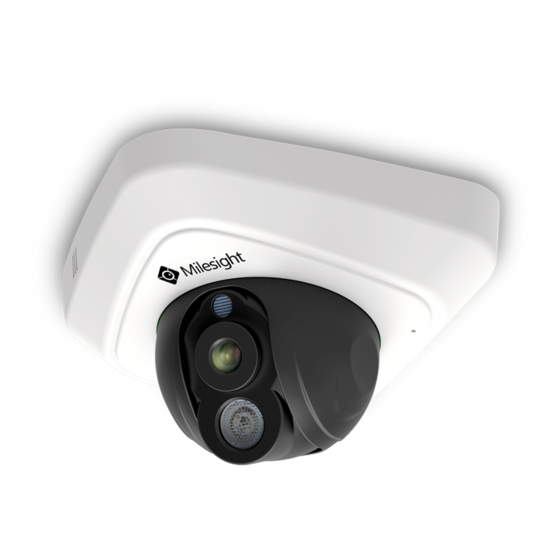
- Page 10 3. Vandal-proof Mini Dome Network Camera IR LEDs Light Sensor Microphone Screw Lens Micro SD/SDHC/SDXC Ethernet Port (PoE) Card Slot Reset Power and System LED Indicator Figure 1-3-3 Vandal-proof Mini Dome Network Camera Note: 1) Error LED Indicator: Error LED Indicator is on when the device starts up or runs error. 2) Reset Button: Press “Reset”...
- Page 11 4. Wi-Fi Mini Cube Network Camera Microphone Lens LED Indicators Light Sensor Speaker IR LEDs PIR Sensor or SIP Button Micro SD/SDHC/SDXC Card Slot SIP Button Power Connector Ethernet Port(PoE) Alarm Input/Output WPS/Reset Button Figure 1-3-4 Wi-Fi Mini Cube Network Camera Note: 1) SIP Button: Trigger alarm via SIP calling.
- Page 12 5. Mini Bullet Network Camera IR LEDs Lens Light Sensor Ethernet Port (PoE) Micro SD/SDHC/SDXC Card Slot Reset Button Figure 1-3-5 Mini Bullet Network Camera Note: 1) Only PoE is available for power supply. 2) Reset Button: Press “Reset” button for 5 seconds, the device will be restored to factory default. File Format:MS-QR-JS-04 Rev1.0 Durability Date:1Year...
- Page 13 6. Remote Focus&Zoom Mini Bullet Network Camera IR LEDs Lens Light Sensor Ethernet Port (PoE) DC 12V Micro SD/SDHC/SDXC Reset Button Card Slot Figure 1-3-6 Remote Focus&Zoom Mini Bullet Network Camera Note: 1) DC 12V and PoE are available for power supply. 2) Reset Button: Press “Reset”...
- Page 14 7. Pro Bullet Network Camera Micro SD/SDHC/SDXC Card Slot Reset Breathe IR LEDs Lens Light Sensor Figure 1-3-7 Pro Bullet Network Camera Note: 1) DC 12V and PoE are available for power supply. 2) Reset Button: Press “Reset” button for 5 seconds, the device will be restored to factory default. 3) There are two versions for Pro Bullet: the interface’s pictures are as following.
- Page 15 Ethernet Port (PoE) Alarm/Audio DC 12V Figure 1-3-8 Pro Bullet Network Camera(Version A) Audio In/Out Ethernet Port (PoE) Alarm In/Out DC 12V Figure 1-3-9 Pro Bullet Network Camera(Version B) File Format:MS-QR-JS-04 Rev1.0 Durability Date:1Year...
- Page 16 8. Pro Dome Network Camera Microphone Lens Light Sensor IR LEDs Reset Micro SD/SDHC/SDXC Card Slot Figure 1-3-10 Pro Dome Network Camera Note: 1) Reset Button: Press “Reset” button for 5 seconds, the device will be restored to factory default. File Format:MS-QR-JS-04 Rev1.0 Durability Date:1Year...
- Page 17 DC 12V Alarm In/Out & Audio Out/DC 12V Ethernet Port (PoE) Water-proof Connector Figure 1-3-11 Pro Dome Network Camera multiple interface Here is one equipped cable for multiple interface usage: Ethernet Port DC 12V (PoE) Alarm In/Out Audio Out Alarm In/Out & Ethernet Port Audio Out/DC 12V (PoE)
-
Page 18: How To Connect To Alarm Interface
1.4 How to Connect to Alarm Interface External interface of camera is as the following, you can refer to the picture to install the external alarm device: PIN1: Alarm Output NC/NO 24V DC 1A PIN2: Alarm Output NC/NO 24V DC 1A PIN3: Alarm Input NC/NO ≤12V PIN4: Alarm Input NC/NO ≤12V 1.5 How to Connect the Water-proof Connector... -
Page 19: System Requirements
Step4: Place the O-Ring on the network port connector. Step5: Connect to RJ45 and the connector of camera, screw the screw bolt and the connector. 1.6 System Requirements Operating System: Windows XP/Vista/7/8/10/Server 2000/Server 2008 CPU: 1.66GHz or higher RAM: 1G or higher Graphic memory: 128MB or more Internet protocol: TCP/IP (IPv4/IPv6) Web Browsers: Internet Explorer 8.0 and above version, Mozilla Firefox, Google Chrome and Safari. -
Page 20: Chapter Ii Network Connection
Chapter II Network Connection 2.1 Setting the Camera over the LAN Connecting the camera to a switch or a router is the most common connection method. The camera must be assigned an IP address that is compatible with its LAN. 2.1.1 Connect the Camera to the PC Directly In this method, only the computer connected to the camera will be able to view the camera. - Page 21 Step5: Configure the DDNS settings in the setting interface of the router; Step6: Visit the camera via the domain name. Figure 2-2 Connect the network camera via a router using dynamic IP File Format:MS-QR-JS-04 Rev1.0 Durability Date:1Year...
-
Page 22: Chapter Iii Accessing The Network Camera
3.1 Assigning An IP Address The Network Camera must be assigned an IP address to be accessible. The default IP address of Milesight Network Camera is 192.168.5.190. The default user name is “admin”, and password is “ms1234”. You can either change the IP address of the camera via Smart Tools or browser. Please connect the camera in the same LAN of your computer. - Page 23 Step3: Select a camera or multiple cameras according to the MAC addresses; Figure 3-1-2 Select single camera Figure 3-1-3 Select multiple cameras File Format:MS-QR-JS-04 Rev1.0 Durability Date:1Year...
- Page 24 Step4: Type the User Name and Password (if they are not the default value.); Figure 3-1-4 Type the User Name and Password Step5: Change the IP address or other network values, and then click “Modify” button; Figure 3-1-5 Modify File Format:MS-QR-JS-04 Rev1.0 Durability Date:1Year...
-
Page 25: Assign An Ip Address Via Browser
Step6: Change the IP address successfully; Figure 3-1-6 Change IP address successfully Step7: By double clicking the selected camera, you can access the camera via web browser directly. The Internet Explorer window will pop up. Figure 3-1-7 Login interface More usage of Smart Tools, please refer to the Smart Tools User Manual. 3.1.2 Assign An IP Address via Browser If the network segment of the computer and that of the camera are different, please follow the steps to change the IP address:... - Page 26 Click “Advanced”, and then click “IP settings” “IP address” “Add” (See Figure 3-1-9). In the pop-up window, enter an IP address that in the same segment with Milesight network camera ( e.g. 192.168.5.61, but please note that this IP address shall not conflict with the IP address on the existing network);...
- Page 27 Step2: Start the browser. In the address bar, enter the default IP address of the camera: http://192.168.5.190; Step3: Enter the user name and password when the LOGIN page appears; Default user name: admin Default password: ms1234 Figure 3-1-10 Login Step4: After login, please select “Configuration” “Basic Settings” “Network” “TCP/IP”. The Network Settings page appears (Shown as following Figure);...
-
Page 28: Accessing From The Web Browser
Figure 3-2-2. Please click “Finish” and refresh the browser, then you will see the video. Figure 3-2-2 Finish installation If IE9 or higher version browser is used, it is suggested that the Milesight camera web link should be added as a trusted site. See the instructions as follows: Step1: Start the IE9 or higher version browser, and select “Tools”... - Page 29 Figure 3-2-3 To add the permission Step2: Select “Security” to “Trusted”; Figure 3-2-4 To trust the control Step3: Enter the IP address of the camera in the blank and click “Add”; Figure 3-2-5 Add the website to the zone File Format:MS-QR-JS-04 Rev1.0 Durability Date:1Year...
-
Page 30: Accessing From Milesight Vms (Video Management Software)
The interface of Milesight VMS is very easy to use, intuitive, with easy access to the most common activities, such as viewing live video, searching through recordings and exporting videos and snapshots. -
Page 31: Chapter Iv System Operation Guide
Chapter IV System Operation Guide 4.1 Live Video After logging in the network camera web GUI successfully, user is allowed to view live video as follows. Figure 4-1-1 Live view interface Table 4-1-1 Description of the buttons Parameter Description Navigation key is used to control the direction. The rotation key is used for auto-rotation under the E-PTZ mode PTZ Control... - Page 32 Default Settings: Restore brightness, contrast and saturation to default settings Click to access the configuration page Choose the Stream (Primary/Secondary/Tertiary)to show on the current video window Only available for camera whose software version is 43 or above Web Components: Support Firefox, Safari, Chrome (Chrome version 44 or below);...
-
Page 33: Playback
Adjust iris automatically if check this box ( Only work when your camera is equipped with P-Iris) Start/Stop live view Click to capture the current image and save to the configured path. The default path is Capture C:VMS\+-1\ IMAGE-MANUAL Click to start recording video and save to the configured path. - Page 34 Step2: Click the date button, choose the date when date window pops up; Figure 4-2-2 Search Video Note: 1) The date with bright red means there is recorded file in this day; one with dark red means weekend day; one with blue background means the date is selected now. Step3: Click to play the video files found on this date.
-
Page 35: Basic Settings
Zoom On/Off Full Screen Note: 1) Drag the progress bar with the mouse to locate the exact playback point. You can also input to locate the playback point in the Set Playback Time filed. You can the time and click also click to zoom out/in the progress bar. -
Page 36: Image
Tertiary Stream Settings Figure 4-3-3 Tertiary Stream Table 4-3-1 Description of the buttons Parameters Function Introduction There are difference for the camera with “-A” and “-B” Video Codec -A: H.264/MJPEG are available -B: H.265/H.264/MJPEG are available Options include 4M(2592*1520), 3M(2304*1296), 3M(2048*1536), Frame Size 1080P(1920*1080), 2M(1600 *1200), 1.3M(1280*960), 720P(1280*720), D1 (704*576) - Page 37 Display Figure 4-3-4 Display Table 4-3-2 Description of the buttons Parameters Function Introduction Power Line Frequency 60HZ flicker for NTSC mode and 50HZ flicker for PAL mode There are several parameters such as Exposure Level, Maximum Exposure Time and IR-CUT Interval, etc, associated with this mode Night Mode: Shown in live view based on Night Mode settings Day Mode: Shown in live view based on Day Mode settings Day/Night Mode...
- Page 38 Rotating 180°: The images is presented upside down Rotating 270°: The images is presented rotating 270° Enhancement Figure 4-3-5 Enhancement (H.264 series) Figure 4-3-6 Enhancement (H.265 series) Table 4-3-3 Description of the buttons Parameters Function Introduction There is an option to turn On/Off the IR LED. Select smart IR on, and the IR LED Smart IR changes according to the actual illumination.
- Page 39 Incandescent Lamp: Select this option when light is similar with incandescent lamp Warm Light Lamp: Select this option when light is similar with warm light lamp Natural Light: Select this option when there is no else light but natural light Fluorescent Lamp: Select this option when light is similar with Fluorescent Lamp This function is only for H.264 series, better image for moving objects, it may...
- Page 40 Figure 4-3-7 Anti-fog Image Figure 4-3-8 HLC Image Day/Night Mode Figure 4-3-9 Day/Night Mode File Format:MS-QR-JS-04 Rev1.0 Durability Date:1Year...
- Page 41 Table 4-3-4 Description of the buttons Parameters Function Introduction Exposure Level Level 0~10 are available to meet your need Maximum Exposure Set the maximum exposure time to 1/5~1/100000 Time IR-CUT Interval The interval to keep the mode from switching IR-CUT Choose to turn on or turn off under this mode IR LED Choose to turn on or turn off under this mode...
-
Page 42: Audio
4.3.3 Audio This audio function allows you to hear the sound from the camera or transmit your sound to the camera side. A two-way communication is also possible to be achieved with this feature. Alarm can be triggered when the audio input is above a certain alarm level you set, and configured audio can be played when an alarm occurs. - Page 43 Figure 4-3-12 Wi-Fi Table 4-3-7 Description of the buttons Parameters Function Introduction Enable Wi-Fi Enable/Disable the Wi-Fi function Wi-Fi Status: Connected/Disconnected SSID: Wi-Fi source Network Mode: Wi-Fi option for Manage and Ad-Hoc mode Wi-Fi Settings Security Mode: Select Wi-Fi connection security mode Encryption Type: Auto/TKIP/AES are available Key: Enter the Key of Wi-Fi to connect Enable DHCP: Check the checkbox to enable the DHCP function...
-
Page 44: Network
Push-Button Method The user simply has to push a button, either an actual or virtual one, on both the access point and the new wireless client device. Support of this mode is mandatory for access points and optional for connecting devices. Figure 4-3-13 WPS Table 4-3-8 Description of the buttons Parameters... - Page 45 Table 4-3-9 Description of the buttons Parameters Function Introduction Get IPv4 Address Get an IP address from the DHCP server automatically Automatically IPv4 Address: An address that used to identify a network camera on the network IPv4 Subnet Mask: It is used for identifying the subnet where the network camera is located IPv4 Default Router: The default router address Use fixed IP address...
- Page 46 HTTP URL are as following: Stream Main Steam http://username:password@IP:port/ipcam/mjpeg.cgi Secondary Stream http://username:password@IP:port/ipcam/mjpegcif.cgi Tertiary Stream http://username:password@IP:port/mjpegthird.cgi Note: 1) You need to change the codec type of streams to MJPEG expect the main stream of H.264 cameras whose models with “-A”. RTSP Figure 4-3-16 RTSP Settings Table 4-3-11 Description of the buttons Parameters...
-
Page 47: Date&Time
Secondary Stream rtsp://username:password@IP:port/sub Tertiary Stream http://username:password@IP:port/third Note: 1) DSCP refers to the Differentiated Service Code Point; and the DSCP value is used in the IP header to indicate the priority of the data. 2) A reboot is required for the settings to take effect. 3) The tertiary stream is only equipped on camera whose model with “-A”... -
Page 48: Advanced Settings
By using Milesight ROI technology, more than 50% of bit rate can be saved and therefore less bandwidth demanded and the storage usage reduced. So according to this, you can set a small bit File Format:MS-QR-JS-04 Rev1.0... -
Page 49: Network
rate for high resolution. Figure 4-4-2 ROI Settings Table 4-4-2 Description of the buttons Parameters Function Introduction Enable Check the checkbox to enable the ROI function Clear All Clear all areas you drew before Video Stream Choose the Video Stream Note: 1) You can set a low bit rate. - Page 50 Table 4-4-3 Description of the buttons Parameters Function Introduction Enable Check the checkbox to enable the UPnP function Enable Port Mapping Check the checkbox to enable the Port Mapping Name The name of the device detected online can be edited Auto: Automatically obtain the corresponding HTTP and RTSP port, without any settings Type...
- Page 51 Figure 4-4-5 SMTP Settings Table 4-4-5 Description of the buttons Parameters Function Introduction User Name The sender's name. It is usually the same as the account name Sender Email Address Email address to send video files attached emails Password The password of the sender Server Address The SMTP server IP address or host name(e.g.
- Page 52 Table 4-4-6 Description of the buttons Parameters Function Introduction Server Address FTP server address Server Port The port of the FTP server. Generally it is 21 User Name User name used to log in to the FTP sever Password User password FTP Folder Name Path where video will be uploaded to on the FTP server VLAN...
- Page 53 Note: 1) The obtained IP address is dynamically assigned via PPPoE, so the IP address always changes after rebooting the camera. To solve the inconvenience of the dynamic IP, you need to get a domain name from the DDNS provider (e.g. DynDns.com). 2) The user name and password should be assigned by your ISP.
-
Page 54: Alarm
Read Security Name Input the name of Read Security Community Level of Security There are three levels available: (auth, priv), (auth, no priv) and (no auth, no priv) Write Security Name Input the name of Write Security Community Level of Security There are three levels available: (auth, priv), (auth, no priv) and (no auth, no priv) SNMP Port The port of SNMP, the default is 161... - Page 55 Step2: Set motion detection schedule; Figure 4-4-11 Schedule Settings Step3: Set alarm action; Figure 4-4-12 Alarm Action Table 4-4-8 Description of the buttons Parameters Function Introduction Save Into SD Card Save alarm recording files into SD Card Save Into NAS Save alarm recording files into NAS Upload Via FTP Upload the recording files via FTP...
- Page 56 HTTP Notification Support to pop up the alarm news to specified HTTP URL. NOTE: The HTTP notification function is just one way for camera to send messages to VMS Software. And it's the VMS that defines what the messages mean and decides what to do after receiving this kind of messages.
-
Page 57: Audio Alarm
Step4: If successfully, you can see the device icon turns yellow in the Surveillance when the camera is under Motion Detection Alarm; So, it's the VMS Software which decides whether we can use this function successfully. Step5: Set alarm settings. Figure 4-4-13 Alarm Settings Table 4-4-9 Description of the buttons Parameters... - Page 58 Figure 4-4-14 Schedule Settings Figure 4-4-15 Alarm Settings The meaning of items please refer to table 4-4-8 and 4-4-9, here will not repeat again. External Input Figure 4-4-16 Schedule Settings File Format:MS-QR-JS-04 Rev1.0 Durability Date:1Year...
-
Page 59: Other Alarm
Figure 4-4-17 Alarm Settings The meaning of items please refer to table 4-4-8 and 4-4-9, here will not repeat again. Other Alarm Figure 4-4-18 Other Alarm Table 4-4-10 Description of the buttons Parameters Function Introduction Network Lost, Tampering and IP Address Conflicted are available Alarm Type Check the checkbox to enable the alarm type you selected File Format:MS-QR-JS-04 Rev1.0... - Page 60 Save Into SD Card: Save alarm recording files into SD Card External Output: If the camera equips with External Output, you can enable the action after configuring the trigger duration Alarm Action Play Audio: If the camera equips with Speaker, you can enable the action after configuring the audio speaker Play Buzzer: If the camera equips with Buzzer, you can check the checkbox to enable the function...
-
Page 61: Storage
Step2: Set region detection schedule; Step3: Set alarm action; Step4: Set alarm settings. Figure 4-4-21 Alarm Settings The meaning of items please refer to table 4-4-8 and 4-4-9, here will not repeat again. 4.4.4 Storage Before you start: To configure record settings, please make sure that you have the network storage device within the network or the SD card inserted in your camera. -
Page 62: Record Schedule
Table 4-4-11 Description of the buttons Parameters Function Introduction Format Format SD card, the files in SD card will be removed Mount/UnMount Mount/Dismount SD card Enable cyclic storage Enable/Disable cyclic storage Enable cyclic storage, when the free disk space reach at a certain time, it will Delete automatically delete the files at certain percentage according to your settings Record Schedule... - Page 63 The network disk should be available within the network and properly configured to store the recorded files, etc. NAS (Network-Attached Storage), connecting the storage devices to the existing network, provides data and files services. Figure 4-4-24 NAS Settings Table 4-4-13 Description of the buttons Parameters Function Introduction Server Address...
- Page 64 Figure 4-4-25 SD Card Explore Snapshot Figure 4-4-26 Snapshot Settings Table 4-4-14 Description of the buttons Parameters Function Introduction Enable Time Snapshot: Check the checkbox to enable the Timing Snapshot function Snapshot Settings Interval: Set the snapshots interval, input the number and choose the unit(millisecond, second, minute, hour, day) File Format:MS-QR-JS-04 Rev1.0 Durability Date:1Year...
-
Page 65: Security
Save Into SD Card: Save the snapshots into SD card, and choose the file name to add time suffix or overwrite the base file name. Save Into NAS: Save the snapshots into NAS, and choose the file name to add time suffix or overwrite the base file name Upload Via FTP: Upload the snapshots via FTP, and choose the file name to add time suffix or overwrite the base file name... -
Page 66: Access List
deleted) Operator An operator can manage all configuration pages except the User page Viewer A viewer can`t change any settings Anonymous Visit Set the Anonymous visit permission Enable or Disable in the drop-down list to enable or disable the anonymous visit. There will be a checkbox of Anonymous next time you logging in. Figure 4-4-28 Log in interface Click Anonymity and log in. -
Page 67: Sip
Internet Protocol(IP) networks. This page allows user to configure SIP related parameters. Milesight cameras can be configured as SIP endpoint to call out when alarm triggered; or allow permitted number to call in to check the video if the video IP phone is used. - Page 68 User ID SIP ID User Name SIP account name Password SIP account password Server Address Sever IP address Server Port Sever port Video Stream Choose the video stream Max Call Duration The max call duration when use SIP Note: 1) SIP supports Directly IP call; 2) SIP only supports second stream with H.265/H.264 or MPEG4 Video Compression.
-
Page 69: Logs
Table 4-4-19 Description of the buttons Parameters Function Introduction Phone Type Phone Number(Call by phone number) & Direct IP Call Phone Number/ Including the phone number or IP address on the white list IP Address Enable White List When enabled, only the designated phone number or IP address can visit Number Filter 4.4.7 Logs The logs contain the information about the time and IP that has accessed the camera through web. -
Page 70: System
4.5 System All information about the hardware and software of the camera can be checked on this page. Figure 4-5-1 System Information Table 4-5-2 Description of the buttons Parameters Function Introduction Device Name The device name can be customized. It will be seen in file names of video files Product Model The product model of the camera Hardware Version... - Page 71 Figure 4-5-2 Maintenance Table 4-5-3 Description of the buttons Parameters Function Introduction Hardware Version: The hardware version of the camera Upgrade Firmware Software Version: The software version of the camera Kernel Version: The kernel version Firmware File: Select the firmware used to upgrade Reboot the device: Click “Reboot”...
-
Page 72: Chapter V Services
Chapter V Services Milesight Technology Co., Ltd provides customers with timely and comprehensive technical support services. End-users can contact your local dealer to obtain technical support. Distributors and resellers can contact directly with Milesight for technical support. Technical Support Mailbox: support@milesight.com Web: http://www.milesight.com...
Need help?
Do you have a question about the MS-C2181-PA and is the answer not in the manual?
Questions and answers