Table of Contents
Advertisement
Advertisement
Table of Contents

Related Manuals for Milesight MS-C2961 Series


Summary of Contents for Milesight MS-C2961 Series
- Page 1 PTZ Network Camera User Manual V2.20...
- Page 2 Thank you for purchasing our product. If there is any questions or requests, please do not hesitate to contact your dealer. This manual is applicable to the Milesight PTZ Network Camera, series are shown as follows, unless otherwise noted. Milesight PTZ Network Camera...
- Page 3 Milesight Technology Co., Ltd (Hereinafter referred to as Milesight). Milesight reserves the right to change this manual and the specifications without prior notice. The latest specifications and user documentation for all Milesight products are available on our official website www.milesight.com...
- Page 4 Cautions Make sure that the power supply voltage is correct before using the camera; Do not store or install the device in extremely hot or cold temperatures, as well as dusty or damp locations, and do not expose it to high electromagnetic radiation; ...
-
Page 5: Table Of Contents
3.2 Accessing from the Web Browser ..................17 3.2.1 Access with Plugin ....................... 17 3.2.2 Access without Plugin ....................19 3.3 Accessing from Milesight VMS (Video Management Software) ........... 20 Chapter IV System Operation Guide....................21 4.1 Live Video..........................21 4.1.1 Operations on Live View Page..................21 4.1.2 3D Positioning......................23... - Page 6 4.6.4 Face Detection(Optional)..................108 4.7 LPR(Optional)........................112 4.7.1 Live Video........................112 4.7.2 Settings........................113 4.7.3 Smart Search......................126 4.8 System..........................128 4.9 Maintenance........................130 4.9.1 System Maintenance....................130 4.9.2 Auto Reboot.......................132 Chapter V Services ..........................133...
-
Page 7: Chapter I Product Description
Chapter I Product Description 1.1 Product Overview Milesight provides a consistent range of cost-effective and reliable network cameras to fully meet your requirements. Based on embedded Linux operating system, Milesight network cameras could be easily accessed and managed either locally or remotely with great reliability. -
Page 8: Hardware Overview
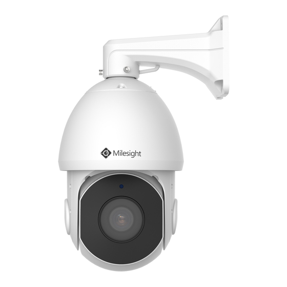
1.3 Hardware Overview Speed Dome Network Camera Figure 1-3-1 Speed Dome Network Camera Note: 1) Only AC 24V is available for Speed Dome power supply. AC 24V and PoE (802.3at) are available for PoE Speed Dome power supply. 2) Reset Button: Press “Reset” button for 5 seconds, then the device will be restored to factory default. - Page 9 (AI) Speed Dome Network Camera II Figure 1-3-2 Speed Dome Network Camera II Note: 1) Only AC 24V is available for Speed Dome II power supply. AC 24V and PoE (802.3at) are available for PoE Speed Dome II power supply. 2) Reset Button: Press “Reset”...
- Page 10 12X Mini PTZ Bullet Network Camera Wall Mount: Pedestal Mount: Mini PTZ Bullet: Mini PoE PTZ Bullet: Figure 1-3-3 12x Mini PTZ Bullet Network Camera Note: 1) Reset Button: Press “Reset” button for 5 seconds, then the device will be restored to factory default.
- Page 11 AI 5X/20X/23X Mini PTZ Bullet Plus Network Camera Figure 1-3-3 AI Mini PTZ Bullet Plus Network Camera Note: 1) Reset Button: Press “Reset” button for 5 seconds, then the device will be restored to factory default. 2) DC 12V and PoE (802.3at) are available for power supply.
- Page 12 (AI) 12X/20X/23X Mini PTZ Dome Network Camera Figure 1-3-4 Mini PTZ Dome Network Camera Note: 1) Reset Button: Press “Reset” button for 5 seconds, then the device will be restored to factory default. 2) DC 12V and PoE (802.3at) are available for power supply.
-
Page 13: How To Connect To Alarm Interface
1.4 How to Connect to Alarm Interface External interface of camera is as the following, you can refer to the picture to install the external alarm device:(Example for PTZ BULLET) PIN1: Alarm Output NC/NO 24V DC 1A PIN2: Alarm Output NC/NO 24V DC 1A PIN3: Alarm Input NC/NO ≤12V PIN4: Alarm Input NC/NO ≤12V 1.5 How to Connect the Water-proof Connector... -
Page 14: System Requirements
1.6 System Requirements Operating System: Windows XP/Vista/7/8/10/Server 2000/Server 2008 CPU: 1.66GHz or higher RAM: 1G or higher Graphic memory: 128MB or more Internet protocol: TCP/IP (IPv4/IPv6) Web Browsers: Internet Explorer 8.0 and above version, Mozilla Firefox, Google Chrome and Safari. -
Page 15: Chapter Ii Network Connection
Chapter II Network Connection 2.1 Setting the Camera over the LAN Connecting the camera to a switch or a router is the most common connection method. The camera must be assigned an IP address that is compatible with its LAN. 2.1.1 Connect the Camera to the PC Directly In this method, only when the computer connected to a camera, it will be able to view the camera. - Page 16 assistance with port forwarding; Step4: Apply a domain name from a domain name provider; Step5: Configure the DDNS settings in the setting interface of the router; Step6: Visit the camera via the domain name. Figure 2-2 Connect the network camera via a router using dynamic IP...
-
Page 17: Chapter Iii Accessing The Network Camera
Step2: Start Smart Tools, click the IPC Tools page, then enter the device information, such as IP address, MAC address, Status, Port number, Netmask, and Gateway, then all related Milesight network cameras in the same network that will be displayed. Details are shown as the figure below;... - Page 18 Step3: Select a camera or multiple cameras according to the MAC addresses; Select single camera Select multiple cameras Step4: If the selected camera shows "Active" in the status bar, you can directly type the User Name and Password (Camera with version lower than 4x.7.0.69 is using admin/ms1234 by default), change the IP address or other network values, and then click “Modify”...
- Page 19 If the selected camera shows "Inactive" in the status bar(Camera with version V4x.7.0.69 or above), click to set the password when using it for the first time. You can also set the security questions when activating the camera in case that you forget the password(You can reset the password by answering three security questions correctly).
-
Page 20: Assign An Ip Address Via Browser
Step5: Change the IP address successfully; Step6: By double clicking the selected camera or the browser of interested camera, you can access the camera via web browser directly. The Internet Explorer window will pop up. More usage of Smart Tools, please refer to the Smart Tools User Manual. 3.1.2 Assign An IP Address via Browser If the network segment of the computer and that of the camera are different, please follow the... - Page 21 Click “Advanced”, and then click “IP settings” “IP address” “Add” (See Figure 3-1-9). In the pop-up window, enter an IP address that in the same segment with Milesight network camera ( e.g. 192.168.5.61, but please note that this IP address shall not conflict with the IP address on the existing network);...
- Page 22 Step2: Start the browser. In the address bar, enter the default IP address of the camera: http://192.168.5.190; Step3: If the camera’s firmware version is lower than V4x.7.0.69, it will directly display the login page, enter the user name and password when the LOGIN page appears; Default user name: admin Default password:...
-
Page 23: Accessing From The Web Browser
Step5: Change the IP address or other network values. Then click “Save” button; Step6: The change of default IP address is completed. 3.2 Accessing from the Web Browser The camera can be used with the most standard operating systems and browsers. The recommended browsers are Internet Explorer, Firefox, Chrome, Microsoft Edge, Safari. - Page 24 If IE9 or higher version browser is used, it is suggested that the Milesight camera web link should be added as a trusted site. See the instructions as follows: Step1: Start the IE9 or higher version browser, and select “Tools” “Internet Options”;...
-
Page 25: Access Without Plugin
As browser security becomes more and more important, some browsers don’t support installing plugin. In order to normally preview the video on the browser, Milesight upgraded the camera to support Plugin-Free Mode. In Plugin-Free Mode, you can preview the video on the browser without plugin. -
Page 26: Accessing From Milesight Vms (Video Management Software)
The interface of Milesight VMS is very easy to use, intuitive, with easy access to the most common activities, such as viewing live video, searching through recordings and exporting videos and snapshots. -
Page 27: Chapter Iv System Operation Guide
Chapter IV System Operation Guide 4.1 Live Video After logging in the network camera web GUI successfully, you are allowed to view live video as follows. 4.1.1 Operations on Live View Page Table 4-1-1 Description of the buttons Parameter Description Navigation key is used to control the direction. - Page 28 Lens Initialization, Auxiliary Focus and Auto Iris Lighting For 30s: Click to open/ close the White LED for lighting 30s. 3D Positioning: Click to enable/ disable 3D positioning. One-touch Patrol: Click to carry out the patrol. Auto Home: Click to enable Auto Home. Manual Tracking: Click to track the moving objects.
-
Page 29: Positioning
Window size Click to display images at a real size. Real size Click to display images at full-screen. Full Screen When recording, the icon will turn red. Recording When an alarm of Smart Event was triggered, the icon appears Alarm When an alarm of Motion Detection was triggered, the icon appears Alarm... -
Page 30: Set / Call A Preset / Patrol / Pattern
Steps: 1.Click on the toolbar of Live View interface. 2.Operate the 3D positioning function Left click a position of the Live View, the corresponding position will be moved to the center of the Live View. Hold down the left mouse button and drag the mouse to the lower right or upper right on the Live View, you can see a blue rectangle. - Page 31 Step2: Use the PTZ control buttons to move the lens to the interested position; Step3: Click to save the setting of the current preset; Step4: Click to delete the chosen preset. Note: Up to 300 presets can be configured. Calling a preset: Select a defined preset form the preset list and click to call the preset.
- Page 32 Set / Call a patrol A patrol is a memorized series of preset function. It can be configured and called on the patrol setting list. You can customize up to 8 patrols and it can be configured with 48 presets. Before configuring the patrol, you should make sure that the presets you want to add to the patrol have been defined.
- Page 33 The duration staying on one patrol point. The PTZ camera Patrol Time moves to another patrol point after the set patrol time. Step5: Click to save the patrol settings. Note: A. Patrol Speed only works in Patrol mode. B. Patrol Time should be 15~120s for Mini PTZ Bullet and 0~120s for Speed Dome. Call a patrol: In the PTZ control panel, select a defined patrol from the patrol list, and click to call the patrol,...
-
Page 34: Playback
The percentage of number on the OSD is the remaining space of pattern. Start with 100% and run out of 0%. Call a pattern: In the PTZ control panel, select a defined pattern from the pattern list, click to call the pattern, as shown in the figure below. - Page 35 Note: 1) The date with bright red means current date; one with a dark red number and white background means weekend day; one with a dark red number and blue background means that the date is selected now. 2) It supports Plugin-free Playback function which allows to preview the playback without installing plugin in Firefox (Version 65 and above) &...
-
Page 36: Local Settings
Start/Stop Recording Snapshot Zoom On/Off Full Screen Note: Drag the progress bar with the mouse to locate the exact playback point. You can also input the time and click to locate the playback point in the Set Playback Time filed. You can also click to zoom out/in the progress bar. - Page 37 Primary Stream Settings Record Stream Type (General) Record Stream Type (Event) Secondary Stream Settings Tertiary Stream Settings...
- Page 38 Table 4-4-1 Description of the buttons Parameters Function Introduction General & Event are available only for Primary Stream. General refers to continuously recording video, while Event includes events that can trigger alarms, such as Motion, Exception, LPR and so on. Record Stream Type This item can set different bit rate and frame rate separately for different Recording Stream Types.
-
Page 39: Image
this item is optional only if you Low/Medium/High/Higher are available, JPEG Quality select the MJPEG Note: The options of [Frame Size] are variable according to the model selected. 4.4.2 Image Display information, enhancement of image and Day/Night setting can be set in this module. OSD (On Screen Display) content and video time can be displayed to rich the image information. - Page 40 This is the sensitivity for switching Night Mode to Day Mode. When IR Light Night To Day Value Sensor Current Value is higher than this value, it will switch Night Mode to Day Mode. IR Light Sensor Value The current value of the IR light sensor With the combination of the High Beam and Low Beam, The IR LEDs technology has been upgraded to provide better image clarity and quality regardless of the object distance.
- Page 41 Enhancement Table 4-4-3 Description of the buttons Parameters Function Introduction There is an option to turn On/Off the IR LED. IR Balance Mode IR Balance Mode would avoid the problem of overexposure or darkness, and the IR LED will change according to the actual illumination. To restore white objects and remove color distortion cause by the light of the environment Auto White Balance: This option will automatically enable the White Balance...
- Page 42 Lamp. Schedule mode: Select this option that you can customize the schedule to enable/disable above modes Enable this function to reduce the motion blur of objects effectively. Reduce Motion Blur You can adjust the deblur level from 1 to 100. Better image effect in foggy weather, refers to Figure 4-4-9 Defog Mode Note:...
- Page 43 General Mode: Enable the general mode of HLC, and there is a setting for HLC Level Enhanced Mode: Enable the enhanced mode of HLC, and there is a setting for HLC Level HLC Level Select level for HLC Day Enhancement Mode BLC/WDR/HLC are available.
- Page 44 4) WDR/HLC has higher priority than exposure settings at the same time frame. 5) Defog Image. 6) HLC Image.
- Page 45 Day/Night Mode Table 4-4-4 Description of the buttons Parameters Function Introduction Exposure Level Level 0~10 are available to meet your need. Minimum Shutter is the same as Maximum Exposure Time. Set the minimum Minimum Shutter Shutter to 1~1/100000s Maximum Shutter is the same as Minimum Exposure Time. Set the maximum Maximum Shutter Shutter to 1~1/100000s IR-CUT Latency...
- Page 46 OSD(On Screen Display) Table 4-4-5 Description of the buttons Parameters Function Introduction Video Stream Enable to set OSD for primary stream and secondary stream Font Size Smallest/Small/Medium/Large/Largest/Auto are available for title and date Font Color Enable to set different color for title and date Enable to set different colors for display information background on screen You can set different colors for font and background of image , then the image OSD will show as below:...
- Page 47 By using Milesight ROI technology, more than 50% of bit rate can be saved and therefore less bandwidth demanded and the storage usage reduced. So according to this, you can set a small bit rate for high resolution.
-
Page 48: Audio
4.4.3 Audio This audio function allows you to hear the sound from the camera or transmit your sound to the camera side. A two-way communication is also possible to be achieved with this feature. Alarm can be triggered when the audio input is above a certain alarm level you set, and configured audio can be played when an alarm occurs. -
Page 49: Network
volume is higher than the alarm level, 0-100. Auto Gain Control: Improve the quality of audio; Audio Output Output Volume: Adjust volume of output. You can upload up to 5 audio files manually to Flash or SD Card on the Audio web page and you can also edit the audio file’s name when upload. - Page 50 Parameters Function Introduction Get IPv4 Address Get an IP address from the DHCP server automatically. Automatically IPv4 Address: It is used to identify a network camera on the network; IPv4 Subnet Mask: It is used for identifying the subnet where the network camera is located;...
- Page 51 Parameters Function Introduction HTTP Enable Start or stop using HTTP. HTTP Port Web GUI login port, the default is 80, the same with ONVIF port. HTTPS Enable Start or stop using HTTPS. HTTPS Port Web GUI login port via HTTPS. the default is 443. HTTP Settings Upload and set the SSL certificate .
- Page 52 RTSP URL are as below: Stream Main Stream rtsp://username:password@IP:port/main Secondary Stream rtsp://username:password@IP:port/sub Tertiary Stream http://username:password@IP:port/third Note: 1) Get the format of RTSP URL by clicking “ ”on the right side of RTSP Port. 2) Get the playback tip by clicking “ ”on the right side of Playback Port.
- Page 53 Host name DDNS name enabled in the account Note: 1)Please do the Port Forwarding of HTTP Port and RTSP Port before you use Milesight DDNS. 2)Make sure that the internal and the external port number of RTSP are the same.
- Page 54 Email Alarm video files can be sent to specific mail account through SMTP server. You must configure the email settings correctly before using it. Table 4-4-13 Description of the buttons Parameters Function Introduction Enable Check the checkbox to enable Email function User Name The sender's name.
- Page 55 Alarm Snapshot File Default(YYYY-MM-DD) /MM-DD-YYYY/ DD-MM-YYYY/ Add prefix/ Overwrite with Name the base file name/ Customize are available. Timing Snapshot File Default(YYYY-MM-DD) /MM-DD-YYYY/ DD-MM-YYYY/ Add prefix/ Overwrite with Name the base file name/ Customize are available. Note: You can refer to the following file name tip to customize the file name. Alarm video files can be sent to specific FTP server.
- Page 56 User Name User name used to log in to the FTP sever Password User password Storage Path where video and image will be uploaded to the FTP server. Storage Path Four FTP storage path types are available, including Root Directory, Parent Directory, Child Directory and Customize.
- Page 57 Note: How to set up VLAN in switches, please refers to your switches user manual. PPPoE This camera supports the PPPoE auto dial-up function. The camera gets a public IP address by ADSL dial-up after the camera is connected to a modem. You need to configure the PPPoE parameters of the network camera.
- Page 58 Table 4-4-15 Description of the buttons Parameters Function Introduction The version of SNMP, please select the version of your SNMP software. SNMP v1: Provide no security SNMP v1/2/3 SNMP v2: Require password for access SNMP v3: Provide encryption and the HTTPS protocol must be enabled Write Community Input the name of Write Community Read Community...
- Page 59 1) The settings of SNMP software should be the same as the settings you configure here; 2) A reboot is required for the settings to take effect. 802.1x The IEEE 802.1X standard is supported by the network cameras, and when the feature is enabled, the camera data is secured and user authentication is needed when connecting the camera to the network protected by the IEEE 802.1X.
- Page 60 24hrs to activate the account for using live function. 2) For RTMP, since G.711 is not available for YouTube, so you can only play video from Milesight Network Camera with H.264 video coding and AAC audio coding on YouTube.
-
Page 61: Date&Time
4.4.5 Date&Time Current System Time Current date&time of the system Set the System Time Table 4-4-16 Description of the buttons Parameters Function Introduction Time Zone Choose a time zone for your location. Daylight Saving time Enable the daylight saving time. NTP server Input the address of NTP server. -
Page 62: Advanced Settings
Manual Set the system time manually. Synchronize with Synchronize the time with your computer. computer time 4.5 Advanced Settings 4.5.1 Storage Before you start: To configure record settings, please make sure that you have the network storage device within the network or the SD card inserted in your camera. - Page 63 Table 4-5-2 Description of the buttons Parameters Function Introduction Server Address IP address of NAS server File Path Input the NAS file path, e.g. “\path”. NFS and SMB/CIFS are available. And you can set the user name and password to Mounting Type guarantee the security if SMB/CIFS is selected Note:...
- Page 64 Snapshot Settings Table 4-5-4 Description of the buttons Parameters Function Introduction Enable Timing Snapshot: Check the checkbox to enable the Timing Snapshot function Interval: Set the snapshots interval, input the number and choose the unit(millisecond, second, minute, hour, day) Save Into Storage: Save the snapshots into SD card or NAS, and choose the file name to add time suffix or overwrite the base file name.
-
Page 65: Security
(Note: Files are visible once SD card is inserted. Don’t insert or pull out SD card when power on.) Video files are arranged by date. Set file type and start/end time to search out files. Each day files will be displayed under the corresponding date, from here you can copy and delete files etc. You can visit the files in SD card by ftp, for example, ftp://username:password@192.168.5.190(user name and password are the same as the camera account and the IP followed is the IP of your device.). - Page 66 Table 4-5-5 Description of the buttons Parameters Function Introduction Allow anonymous viewing: Check the checkbox to enable visit from whom Manage Privilege doesn’t have account of the device Click “Edit” button to set three security questions for your camera. In case that you forget the password, you can click “Forget Password”...
- Page 67 Click “Add” button, it will display Account Management page. You can add an account to the camera by entering Admin Password, User Level, User Name, New Password, Confirm, and edit user privilege by clicking . The added account will be displayed in the account list. Admin Password: You can add an account only after you enter the correct admin password.
- Page 68 Refresh Click to get latest status of user accessing to camera. Record serial number of user logging in camera. Note: 1) There are at most 30 records shown on the list. 2) There is only one record if the same user logging in camera by the same IP address.
-
Page 69: Sip
Internet Protocol(IP) networks. This page allows user to configure SIP related parameters. Milesight cameras can be configured as SIP endpoint to call out when alarm triggered; or allow permitted number to call in to check the video if the video IP phone is used. - Page 70 Note: SIP phone and the camera should in the same network segment. Method2: Account registration mode 1) Before using the SIP, you need to register an account for the camera from the SIP server; 2) Register another user account for the SIP device from the same SIP server; 3) Call the camera User ID from the SIP device, you will get the video on the SIP device.
- Page 71 Connection UDP/TCP Protocol Video Stream Choose the video stream Max Call Duration The max call duration when use SIP Note: SIP supports Directly IP call. Alarm Phone List Table 4-5-10 Description of the buttons Parameters Function Introduction Phone Number(Call by phone number) & Direct IP Call(Check to accept peer to Phone Type peer IP call).
-
Page 72: Ptz
Enable White List When enabled, it can only visited by the designated phone number or IP Number Filter address. 4.5.4 PTZ PTZ Settings provides you to configure the functions and parameters about Pan/Tilt/Zoom. PTZ parameters are mainly include the Basic parameters, Auto Home, PTZ Limits, Initial Position(Mini PTZ Bullet), Privacy Mask, Scheduled Tasks, Auto Tracking, Config Clear, RS485(Speed Dome). - Page 73 Configure the OSD parameter, you can set the Zoom status OSD, Pan&Tilt Status, PTZ OSD Preset Status with Always Close/Always Open/2s/5s/10s, and Patrol Status, Pattern Status, Auto Scan Status with Always Open/ Always Close. If you enabled Preset Freezing, the live view of preset position will be showed Preset directly instead of showing both the moving path to the position and the live view.
- Page 74 Auto Home allows the PTZ camera to return to a predefined Home Position automatically after a period of latency time. Check the checkbox to enable the Auto Home mode. Table 4-5-13 Description of the buttons Parameters Function Introduction Latency Time Set a latency time to trigger Auto Home mode, 5-720s.
- Page 75 You can configure the Initial Position for PTZ cameras as a zero point. Step1: Click the PTZ control buttons as the Initial Position of the Mini PTZ bullet,you can also call a defined preset and set it as the Initial Position. Step2: Click Set to save the position as the Initial Position.
- Page 76 Table 4-5-15 Description of the buttons Parameters Function Introduction Enable Check the checkbox to enable the Privacy Mask function Add the current drawing area as Privacy Mask Clear Clear the current drawing area Clear All Clear all areas you drew before Name Support to customize the name of Privacy Mask Select the color for the privacy areas, there are eight colors available: White,...
- Page 77 Note: 1) The time of each task cannot be overlapped. Up to 10 tasks can be configured for each day. 2) The Scheduled Tasks function is prior to Auto Home function. When these two functions are set at the same time, only the Scheduled Tasks function takes effect. 3) You can click button to select or close all schedule of different kinds of tasks.
- Page 78 Config Clear Here you can clear PTZ configurations, including all PTZ configurations, Presets, Patrols, Patterns, Auto Homes, PTZ Limits , Initial Position(Mini PTZ Bullet), Privacy Masks and Scheduled Tasks. RS485 Here you can clear configure RS485 serial port to control the PTZ of Speed Dome. Protocol, Baudrate, Data Bit, Stop Bit, Parity, Flow Control, PTZ Address should be exactly the same as those of the control device.
-
Page 79: Logs
4.5.5 Logs The logs contain the information about the time and IP that has accessed the camera through web. Table 4-5-16 Description of the buttons Parameters Function Introduction There are five main log types: All Type, Event, Operation, Information, Main Type Exception. - Page 80 Table 4-6-1 Description of the buttons Parameters Function Introduction Enable Motion Check the checkbox to enable Motion Detection function. Detection Sensitivity Sensitivity level, 1~10 Normal and Compatible are available for the option. If the setting of motion Onvif Motion region of the third-party software is different from ours, please set this option to ActiveCells Settings Compatible.
- Page 81 Step4: Set alarm action; Table 4-6-2 Description of the buttons Parameters Function Introduction Save Into Storage Save alarm recording files into SD Card or NAS Upload Via FTP Upload the recording files via FTP. Upload Via Email Upload the files via Email If the camera equips with External Output, you can enable the action after External Output configuring the trigger duration.
- Page 82 NOTE: The HTTP notification function is just one way for camera to send messages to VMS Software. And it's the VMS that defines what the messages mean and decides what to do after receiving this kind of messages. So, we can use the HTTP Notification function of our cameras only if the VMS supports this kind of message format.
- Page 83 Step4: If successful, you can see the device icon turn yellow in the Surveillance when the camera is under Motion Detection Alarm; So, it's the VMS Software which decides whether we can use this function successfully. Step5: Set alarm settings. Table 4-6-3 Description of the buttons Parameters Function Introduction...
- Page 84 Set the audio schedule to trigger different audio files and action times in Audio Action Settings different time, which is corresponded to alarm action. Play Audio Interval Auto/ 10 seconds/ 30 seconds/ 1 minute/ 5 minutes/ 10 minutes are available. Twinkle: The White LED will continuous flashing before recovered;...
- Page 85 Please refer to table 4-6-2 and 4-6-3 to get the meaning of items.
- Page 86 External Input The meaning of items please refer to table 4-6-2 and 4-6-3, here will not repeat again.
- Page 87 External Output Please set the Normal Status firstly, when the Current Status is different with Normal Status, it will lead to the alarm. Exception Table 4-6-4 Description of the buttons Parameters Function Introduction Network Disconnected, IP Address Conflicted, Record Failed, SD Card Full, SD Alarm Type Card Uninitialized, SD Card Error and No SD Card are available Check the checkbox to enable the alarm type you selected...
-
Page 88: Vca Event
4.6.2 VCA Event Smart Event uses Milesight VCA (Video Content Analysis) technology, which provides advanced, accurate smart video analysis for Milesight network cameras. Powered by AI chip,the new generation video analytics is capable of recognizing vast attributes of human, vehicle, and object pattern recognition models. - Page 89 Region Entrance Region entrance helps to protect a special area from potential threat of suspicious person’s or object’s entrance. An alarm will be triggered when objects enter the selected regions by enabling region entrance. Region Entrance Interface (for non-AI cameras) Region Entrance Interface (for AI cameras) Step1: Enable Region Entrance detection and set detecting sensitivity;...
- Page 90 Step3: Set entrance detection region. If you choose Normal Mode, it supports configuring the detection region for the current area. If you choose Advanced Mode (Only for PTZ series), it supports configuring the detection region for different PTZ presets (Only support Preset 1~4 so far);...
- Page 91 Note: 1) Please enable Auto Tracking on the PTZ interface first. 2) PTZ Auto Tracking is checked by default. Region Exiting Region exiting is to make sure that any person or object won't exit the area that is being monitored. Any exit of people or objects will trigger an alarm.
- Page 92 Region Exiting Interface (for AI cameras) Step1: Enable Region Exiting Detection and set detecting sensitivity; Step2: Choose detection object. Check Human or Vehicle attribute, and the camera will alarm once detecting people or vehicle and triggering related events; Note: All AI Cameras support this function. Step3: Set Exiting Detection Region.
- Page 93 Advanced Motion Detection Different from traditional motion detection, Milesight advanced motion detection can filter out “noise” such as lighting changes, natural tree movements, etc. When an object moves in the selected area, it will trigger alarm.
- Page 94 Advanced Motion Detection Interface (for non-AI cameras) Advanced Motion Detection Interface (for AI cameras) Step1: Enable region exiting detection and set detecting sensitivity; Step2: Set Ignore Short-Lived Motion time. If you set the time, when the moving duration of an object is within the setting time, it will not trigger alarm;...
- Page 95 far). Step5: Set object size limits. The object size limits can refer to Table 4-6-5; Step6: Set detection schedule; Step7: Set alarm action; Step8: Set alarm settings. If you enable External Output and choose Constant External Output Action Time, when object motion time is longer than the Ignore Short-Lived Motion time which you set in the selected regions, External Output Action alarm time will be always constant till the alarm is released.
- Page 96 Tamper Detection Tamper Detection is used to detect possible tampering like the camera being unfocused, obstructed or moved. This functionality alerts security staff immediately when any above-mentioned actions occur. Tamper Detection Interface(for non-AI cameras) Tamper Detection Interface (for AI cameras) Step1: Enable Tamper Detection and set detecting sensitivity;...
- Page 97 Step4: Set alarm settings. If you enable External Output and choose Constant External Output Action Time, when possible tampering is detected, External Output Action alarm time will be always constant till the alarm is released. Note: The algorithm supports defocus detection in Tamper Detection function.
- Page 98 Line Crossing Line Crossing detection is designed to work in most indoor and outdoor environment. An event will be triggered every time when the camera detects objects crossing a defined virtual line. Line Crossing Interface(for non-AI cameras) Line Crossing Interface(for AI cameras) Settings steps are shown as follows: Step1: Choose a line number;...
- Page 99 Note: Milesight allows to set up to four lines at a time. There are three direction modes to choose for triggering alarm. “A→B” means when there is any object crossing the line from the “A” side to the “B”...
- Page 100 Loitering When objects are loitering in a defined area for a specific period of time, it would trigger an alarm. Loitering Interface(for non AI-cameras) Loitering Interface(for AI cameras) Step1: Enable Loitering Detection and minimum loitering time; Step2: Choose detection object. Check Human or Vehicle attribute, and the camera will alarm once detecting people or vehicle and triggering related events;...
- Page 101 detection region for the current area. If you choose Advanced Mode (Only for PTZ series), it supports configuring the detection region for different PTZ presets (Only support Preset 1~4 so far). Step4: Set object size limits. The object size limits can refer to Table 4-6-5; Step5: Set detection schedule;...
- Page 102 Also Milesight loitering allows to set “Object Size”. Only the object bigger than the set size will trigger the alarm. Human Detection Human detection is used for figuring out whether an object is a human or not. Once human detection is enabled, when there is an object appearing in the detecting area, an ID will show on the frame.
- Page 103 be always constant till the alarm is released. Object Left/Removed Object Left can detect and prompt an alarm if an object is left in a pre-defined region. Object Removed can detect and prompt an alarm if an object is removed from a pre-defined region. Object Left/Removed Interface(for non-AI cameras)
- Page 104 Object Left/Removed Interface(for AI cameras) Step1: Enable Object Left or Object Removed (Or you can enable both features at the same time); Step2: Set minimum time; Step3: Set detecting sensitivity; Step4: Set detection region. If you choose Normal Mode, it supports configuring the detection region for the current area.
- Page 105 Step8: Set alarm settings. If you enable External Output and choose Constant External Output Action Time, when an object is left/removed from the selected regions, External Output Action alarm time will be always constant till the alarm is released. Note: 1) After setting minimum time from 3s to 1800s, any objects are left in the selected area or removed from the selected area over the minimum time will trigger the alarm.
-
Page 106: People Counting
4.6.3 People Counting People Counting People Counting is able to count how many people enter or exit during the setting period. Settings steps are as shown below: Step1: Enable People Counting; Step2: Set detection line. If you choose Normal Mode, it supports configuring the detection line for the current area. - Page 107 Step7: Set alarm action; Step8: Set alarm settings. If you enable External Output and choose Constant External Output Action Time, when the thresholds reach to a certain value you set, External Output Action alarm time will be always constant till the alarm is released.
- Page 108 Note: Crossing along the direction of the arrow will record as “In”, opposite as “Out”; Regional People Counting When enabling Regional People Counting, users can check the real-time number of people and the time of each person's stay in the detection region. Settings steps are as shown below: Step1: Enable Region People Counting;...
- Page 109 Step6: Set alarm action; Step7: Set alarm settings. If you enable External Output and choose Constant External Output Action Time, when the thresholds exceeds the certain value you set, External Output Action alarm time will be always constant till the alarm is released.
- Page 110 Note: 1) Users can check the real-time number of people and the time of each person's stay in the detection region on Live View interface. 2) For Regional People Counting, please make sure your camera model is MS-CXXXX-XXC. 3) Support up to 4 detection regions for regional people counting. Statistics Report The results during the enabling period will be displayed on “Statistics Report”...
- Page 111 People Counting-Statistics Report (Line Chart) People Counting-Statistics Report (Bar Chart)
- Page 112 Regional People Counting-Statistics Report (Line Chart) Regional People Counting-Statistics Report (Bar Chart) Step 5: Click button to pop up the Export window as shown below, and you can choose File Format to export the report to local. Step 6: Click button to pop up the Statistics Report Settings as shown below.
- Page 113 Set Day. User can choose Everyday to export daily reports, while choosing others to export reports on a specific day of the week; Set Time. User can choose the time of day to export the Statistics Report automatically, click the calendar icon to pop up the following Quick Selection; Set Export Time Range;...
-
Page 114: Face Detection(Optional)
Set the destination path of the automatically exported report. The report can be exported to FTP/Email/Storage automatically as the form of an Excel spreadsheet according to the day, time and export time range you set. Then click “Save”. Note: If the current Statistics Report is generated, it will be saved as a csv form. 4.6.4 Face Detection(Optional) General The Face Detection function can detect the face appearing in the drawn area and support saving... - Page 115 Step1: Enable Face Detection; Step2: Set Min. Object Size; Step3: Set detection region, you can drag the detection region to adjust the size of the region. Only faces in this region will be detected; Step4: Set Shield Region is to make faces in the some places of detection region be not detected. You can draw a Shield Region in the preview interface firstly, then click Add button.
- Page 116 Table 4-6-6 Description of the buttons Parameters Function Introduction Quality Priority, Timeliness Priority, Customize are available. Quality Priority: In this mode, it will push a face screenshot of best quality when the face is detected. Timeliness Priority: In this mode, it will push a face screenshot in the shortest Capture Mode time when the face is detected.
- Page 117 Face Only, Upper Body, Whole Body are available. Face Only: Capture the screenshot of face only. Upper Body: Capture the screenshot of upper body. Snapshot Type Whole Body: Capture the screenshot of whole body. If you check the "Background" option, it will take another screenshot of the entire image.
-
Page 118: Lpr(Optional)
4.7 LPR(Optional) 4.7.1 Live Video Milesight LPR Camera supports professional LPR Live View interface , it can show the real-time license plate recognition results and display the snapshots of detected license plates ,which realizes a stand-alone LPR solution. LPR mode of Live View interface (Non-AI Series) -
Page 119: Settings
LPR3. LPR1 is for Asian regions, LPR2 is for European regions and the former Soviet Union and LPR3 is for Korea. For more information, please refer to Milesight-Troubleshooting-LPR setting-LPR1, Milesight-Troubleshooting-LPR setting-LPR2, Milesight-Troubleshooting-LPR setting-Korea. (3) There is only Basic Event under Event Tab for LPR cameras. - Page 120 Step1: Enter the license and click Save. When the License Status changes to Valid, the camera can start detecting the license plates. Note: Only LPR2 and LPR3 need to enter a license to activate the LPR function. Step2: The LPR Night Mode supports the optimal LPR night recognition effect by adjusting different parameter levels.
- Page 121 Auto Mode Step3: Check the checkbox “Enable License Plate Recognition”, you can draw the screen to select area interested. Table 4-7-1 Description of the buttons Parameters Function Introduction License Generated by camera’s information. (Only for LPR2 and LPR3) License Status and Invalid.
- Page 122 Draw the screen to select the area interested, then click “Add”button to add the area, only four recognition areas can be added. You can edit the name of the area or delete the area in the list below. Note: Only license plates larger than 150 pixels can be recognized. Clear Click the "Clear"...
- Page 123 Table 4-7-2 Description of the buttons Parameters Function Introduction Always: in this mode, camera will always detect license plates. Detection Trigger Alarm Input: in this mode, camera will only detect license plates during Alarm Input is being triggered. You can set the confidence level from 1 to 10. Confidence Level When the confidence level of the license plate is higher than the set (Only for LPR1 and LPR2)
- Page 124 LPR camera can use the API URL to send LPR information to back-end devices when the license plate is recognized. API URL format fills as below: HTTP Notification URL http://IP:Port/api/lpr? Note: It supports HTTPS for HTTP Post. User Name Receiver name Password Receiver Password Note:...
- Page 125 Table 4-7-3 Description of the buttons Parameters Function Introduction Small/Medium/Large are available for OSD information. Font Size Note: Snapshot OSD font size and Image OSD font size are corresponded. Enable to set different color for OSD information. Font Color Note: Snapshot OSD font color and Image OSD font color are corresponded.
- Page 126 “-”, “_” and Space are available for File Name Separator format. Separator The default separator is “-”. You can customize the snapshot file name according to items chosen. Item of File Name Each time when an item is checked, the list will add the item row, including the item name and sorting operation.
- Page 127 Once license plate is recognized, and the snapshot will be uploaded via FTP or Email or stored on your local LPR Picture File Path. Then, You can see the snapshot file name which you customize as shown below: Recognized successfully Recognized failed License plate snapshot Recognized successfully License plate snapshot Recognized failed...
- Page 128 Table 4-7-4 Description of the buttons Parameters Function Introduction Enter the license plate and select the license plate type as black or white, set Valid Time and add a note for the license plate, then click the “Add” button, the license plate will be added successfully.
- Page 129 And then set the license plate to Schedule Mode and choose a custom schedule rule that can configure the license plate as Black List or White List at different times. Note: Support setting up to 4 Schedule Rules for Schedule Mode. Note: It supports adding 1000 Black List and White List.
- Page 130 Step4: Set alarm settings. After that, when a license plate marked as “black” is detected, the camera will respond accordingly to your settings. White List Mode Step1: Check the checkbox to enable White List Mode. Step2: Schedule Settings. You can draw the schedule by clicking Edit button. Step3: Set alarm action.
- Page 131 Step4: Set alarm settings. After that, when a license plate marked as “White” is detected, the camera will respond accordingly to your settings. Visitor Mode Step1: Check the checkbox to enable Visitor Mode. Step2: Schedule Settings. You can draw the schedule by clicking Edit button. Step3: Set alarm action.
-
Page 132: Smart Search
Step4: Set alarm settings. After that, when a license plate that is not marked as "Black" or "White" is detected, the camera will respond accordingly to your settings. 4.7.3 Smart Search The real-time detection results will be displayed on the right side of Smart Search page, including detected time, live screenshot, and license plate. - Page 133 Note: (1) It supports displaying 4,000 logs. (2) Only when there is a SD Card or NAS has been set on the storage management , then the logs can be stored and show on Smart Search page. (3) For Plate Color/Vehicle Color Recognition and Vehicle Type Classification, please make sure your model is MS-CXXXX-XXC.
-
Page 134: System
4.8 System All information about the hardware and software of the camera can be checked on this page. - Page 135 Table 4-8-1 Description of the parameters Parameters Function Introduction Device Name The device name can be customized. It will be seen in file names of video files. Product Model The product model of the camera Hardware Version The hardware version of the camera Software Version The software version of the camera can be upgraded MAC Address...
-
Page 136: Maintenance
4.9 Maintenance 4.9.1 System Maintenance Table 4-9-1 Description of the buttons Parameters Function Introduction Software Version: The software version of the camera. Local Upgrade: Click the “Browse” button and select the upgrading file, then click the “Upgrade” button to upgrade. After the system reboots successfully, the System Upgrade update is done. - Page 137 It will prompt "The current version is the latest version" if your camera is already the latest version. Note: Do not disconnect the power of the device during the update. The device will be restarted to complete the upgrading. Reset settings: Click “Reset” button to reset the camera to factory default settings Keep the IP Configuration: Check this option to keep the IP configuration when resetting the camera.
-
Page 138: Auto Reboot
Note: Export and import the same configuration file. Password must be the same. Reboot Click “Reboot” button to restart the device immediately 4.9.2 Auto Reboot Set the date and time to enable Auto Reboot function. The camera will reboot automatically according to the customized time in case that camera overload after running a long time. -
Page 139: Chapter V Services
Chapter V Services Milesight Technology Co., Ltd provides customers with timely and comprehensive technical support services. End-users can contact your local dealer to obtain technical support. Distributors and resellers can contact directly with Milesight for technical support. Technical Support Mailbox: support@milesight.com Web: http://www.milesight.com...
Need help?
Do you have a question about the MS-C2961 Series and is the answer not in the manual?
Questions and answers