Table of Contents
Advertisement
Quick Links
www.ti.com
User's Guide
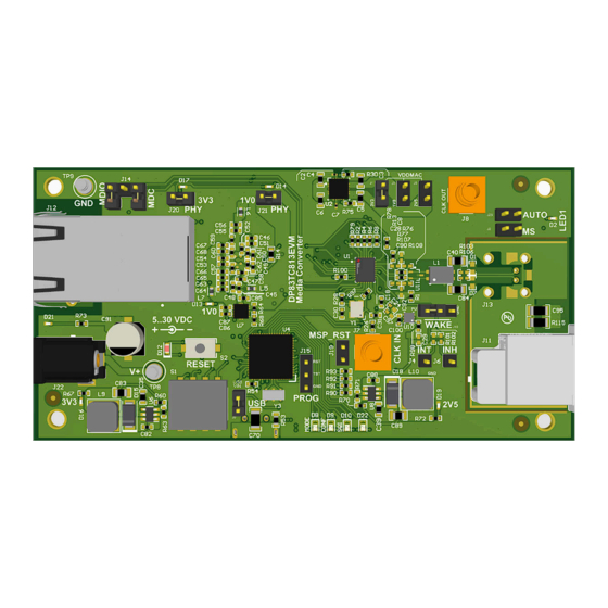
DP83TC813EVM-MC User's Guide
This User's Guide discusses how to properly operate and configure the DP83TC813 Media Converter EVM. For
best layout practices, schematic files, and Bill of Materials, see the associated support documents.
History......................................................................................................................................................................2
2
Introduction.............................................................................................................................................................................3
Features......................................................................................................................................................................3
Setup....................................................................................................................................................4
Details................................................................................................................................................................7
Diagram....................................................................................................................................................................7
3.2 Configuration Options........................................................................................................................................................
4 Definitions...............................................................................................................................................................................
5
Schematics..............................................................................................................................................................................9
Schematic........................................................................................................................................................9
5.2 DP83867 Schematic........................................................................................................................................................
Schematic..............................................................................................................................................................11
5.4 AFE Schematic................................................................................................................................................................
5.5 Comms Schematic...........................................................................................................................................................
Schematic........................................................................................................................................................14
6 Layout....................................................................................................................................................................................
SNVU825 - MAY 2022
Submit Document Feedback
ABSTRACT
Figure 1-1. DP83TC813EVM-MC
Table of Contents
Copyright © 2022 Texas Instruments Incorporated
Table of Contents
DP83TC813EVM-MC User's Guide
7
8
10
12
13
15
1
Advertisement
Table of Contents

Related Manuals for Texas Instruments DP83TC813EVM-MC


Summary of Contents for Texas Instruments DP83TC813EVM-MC
-
Page 1: Table Of Contents
4 Definitions....................................Schematics....................................9 5.1 Main Block Schematic................................9 5.2 DP83867 Schematic................................ 5.3 Power Schematic................................11 5.4 AFE Schematic................................5.5 Comms Schematic................................5.6 Hardware Schematic................................14 6 Layout....................................SNVU825 – MAY 2022 DP83TC813EVM-MC User's Guide Submit Document Feedback Copyright © 2022 Texas Instruments Incorporated... -
Page 2: Revision History
Revision History www.ti.com List of Figures Figure 1-1. DP83TC813EVM-MC..............................Figure 2-1. DP83TC813EVM-MC – Top Side..........................Figure 2-2. DP83TC813EVM-MC – Bottom Side........................Figure 2-3. Onboard Supply Connection and Jumpers....................... Figure 2-4. WAKE Jumper................................Figure 2-5. Onboard MSP Connections for MDIO and MDC.......................5... -
Page 3: Introduction
Introduction 2 Introduction The DP83TC813EVM-MC supports 100-Mbps speed and is IEEE 802.3bw compliant. There is an onboard MSP430F5528 for use with the USB2MDIO graphical user interface tool. The DP83867 is provided for copper (100BASE-TX) support using a RGMII MAC Interface. -
Page 4: Operation - Quick Setup
Introduction www.ti.com Figure 2-2. DP83TC813EVM-MC – Bottom Side 2.2 Operation – Quick Setup 2.2.1 Onboard Power Supply Operation • The EVM can operate from a single supply connected to the turret (TP8: VIN, TP9: GND) or barrel jack connector (J22). -
Page 5: Figure 2-5. Onboard Msp Connections For Mdio And Mdc
To enable analog loopback on the DP83TC813, write 0x0108 to address 0x0016 2.2.3 Master and Slave Mode Selection – DP83TC813 • Master Mode – Place shunt across J2 • Slave Mode – Leave J2 open SNVU825 – MAY 2022 DP83TC813EVM-MC User's Guide Submit Document Feedback Copyright © 2022 Texas Instruments Incorporated... -
Page 6: Figure 2-6. Dp83Tc813 Configured In Autonomous And Slave Modes
LED_1 (D2) will turn only if R17 is populated (DNP by default). This pin is CLKOUT by default and would need to be programmed accordingly. DP83TC813EVM-MC User's Guide SNVU825 – MAY 2022 Submit Document Feedback Copyright © 2022 Texas Instruments Incorporated... -
Page 7: Board Setup Details
USB2MDIO Source or SMA PHY ID + RGMII PHY ID + RGMII Straps CLKOUT Straps Figure 3-1. DP83TC813EVM-MC Block Diagram 3.2 Configuration Options 3.2.1 Clock Configuration • Onboard clock – The onboard crystal is enabled by default • To provide external clock –... -
Page 8: Definitions
Management Data I/O Management Data Clock RGMII Reduced Gigabyte Media Independent Interface Start-of-Frame Detection VDDA Analog Core Supply Rail VDDIO Digital Supply Rail Pull-down Pullup Micro-controller DP83TC813EVM-MC User's Guide SNVU825 – MAY 2022 Submit Document Feedback Copyright © 2022 Texas Instruments Incorporated... -
Page 9: Schematics
867_TX_D2 RX_D2/RX_P 813_RX_D3 TSW-101-07-G-S RX_D3/RX_M 867_TX_D3 10.0k 813_RX_CTRL 867_TX_CTRL RX_DV/RX_CTRL/CRS_DV 813_RX_ER RX_ER 2.2k VSLEEP WAKE_813 WAKE CLKOUT RESET DP83TC813_RESET_N DP83TC813 Figure 5-1. Main Schematic SNVU825 – MAY 2022 DP83TC813EVM-MC User's Guide Submit Document Feedback Copyright © 2022 Texas Instruments Incorporated... -
Page 10: Dp83867 Schematic
0.1uF 0.01uF 0.1uF 0.01uF BLM18KG601SH1 BLM18KG601SH1 10uF 0.1uF 0.01uF 0.1uF 0.01uF 10uF 0.1uF 0.01uF 0.1uF 0.01uF 0.1uF 0.01uF 0.1uF 0.01uF Figure 5-2. DP83867 Schematic DP83TC813EVM-MC User's Guide SNVU825 – MAY 2022 Submit Document Feedback Copyright © 2022 Texas Instruments Incorporated... -
Page 11: Power Schematic
+2V5_REG 22.6k 10uF SS_CTRL2 10uF 15uH NR/SS2 0.1uF SHDN 0.01 µF 47uF 2.26k 10.7k 2.2uF TPS7A8701RTJR B160-13-F 1.02k LMR14206XMKX/NOPB 150040GS73240 Figure 5-3. Power Schematic SNVU825 – MAY 2022 DP83TC813EVM-MC User's Guide Submit Document Feedback Copyright © 2022 Texas Instruments Incorporated... -
Page 12: Afe Schematic
1.00k 1.00k 1.00k 1.00k GND813 GND813 22pF EZAEG3W11AV R113 R114 47pF 100k 100k 4700pF 4700pF 0.01 µF R115 1.0M GND813 Figure 5-4. AFE Schematic DP83TC813EVM-MC User's Guide SNVU825 – MAY 2022 Submit Document Feedback Copyright © 2022 Texas Instruments Incorporated... -
Page 13: Comms Schematic
USB_D_N Rev. sel. 0 Rev. sel. 1 USB1_D_P 1.40k Rev. sel. 2 USB_D_P Rev. sel. 3 10pF 10pF 1.00M USBGND Figure 5-5. Comms Schematic SNVU825 – MAY 2022 DP83TC813EVM-MC User's Guide Submit Document Feedback Copyright © 2022 Texas Instruments Incorporated... -
Page 14: Hardware Schematic
SH-J7 Change the RJ45 connector Change MCU wiring Pin 11, 18 , 50 M7582-05 M7582-05 M7582-05 Change MCU, MDIO wiring Figure 5-6. Hardware Schematic DP83TC813EVM-MC User's Guide SNVU825 – MAY 2022 Submit Document Feedback Copyright © 2022 Texas Instruments Incorporated... -
Page 15: Layout
Schematics 6 Layout Figure 6-1. Top Overlay SNVU825 – MAY 2022 DP83TC813EVM-MC User's Guide Submit Document Feedback Copyright © 2022 Texas Instruments Incorporated... -
Page 16: Figure 6-2. Bottom Overlay
Schematics www.ti.com Figure 6-2. Bottom Overlay DP83TC813EVM-MC User's Guide SNVU825 – MAY 2022 Submit Document Feedback Copyright © 2022 Texas Instruments Incorporated... - Page 17 STANDARD TERMS FOR EVALUATION MODULES Delivery: TI delivers TI evaluation boards, kits, or modules, including any accompanying demonstration software, components, and/or documentation which may be provided together or separately (collectively, an “EVM” or “EVMs”) to the User (“User”) in accordance with the terms set forth herein.
- Page 18 www.ti.com Regulatory Notices: 3.1 United States 3.1.1 Notice applicable to EVMs not FCC-Approved: FCC NOTICE: This kit is designed to allow product developers to evaluate electronic components, circuitry, or software associated with the kit to determine whether to incorporate such items in a finished product and software developers to write software applications for use with the end product.
- Page 19 www.ti.com Concernant les EVMs avec antennes détachables Conformément à la réglementation d'Industrie Canada, le présent émetteur radio peut fonctionner avec une antenne d'un type et d'un gain maximal (ou inférieur) approuvé pour l'émetteur par Industrie Canada. Dans le but de réduire les risques de brouillage radioélectrique à...
- Page 20 www.ti.com EVM Use Restrictions and Warnings: 4.1 EVMS ARE NOT FOR USE IN FUNCTIONAL SAFETY AND/OR SAFETY CRITICAL EVALUATIONS, INCLUDING BUT NOT LIMITED TO EVALUATIONS OF LIFE SUPPORT APPLICATIONS. 4.2 User must read and apply the user guide and other available documentation provided by TI regarding the EVM prior to handling or using the EVM, including without limitation any warning or restriction notices.
- Page 21 Notwithstanding the foregoing, any judgment may be enforced in any United States or foreign court, and TI may seek injunctive relief in any United States or foreign court. Mailing Address: Texas Instruments, Post Office Box 655303, Dallas, Texas 75265 Copyright © 2019, Texas Instruments Incorporated...
- Page 22 TI products. TI’s provision of these resources does not expand or otherwise alter TI’s applicable warranties or warranty disclaimers for TI products. TI objects to and rejects any additional or different terms you may have proposed. IMPORTANT NOTICE Mailing Address: Texas Instruments, Post Office Box 655303, Dallas, Texas 75265 Copyright © 2022, Texas Instruments Incorporated...
Need help?
Do you have a question about the DP83TC813EVM-MC and is the answer not in the manual?
Questions and answers