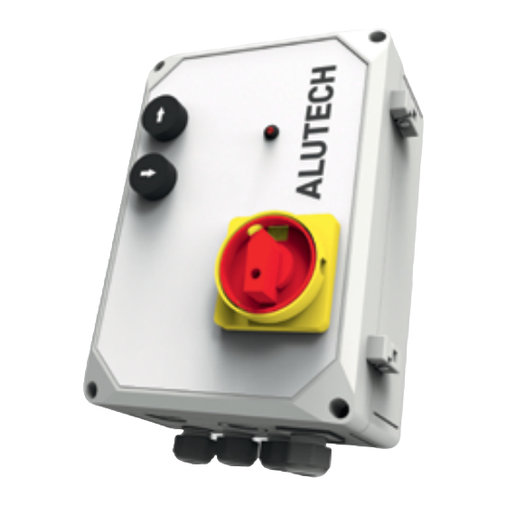
Summary of Contents for Alutech CUL11
- Page 1 CONNECTION English AND OPERATIONAL MANUAL Control unit CUL11 2020 www.alutech-group.com...
-
Page 3: Table Of Contents
..... Due to the constant improvement of construction, ALUTECH Door Systems LLC reserves the right to change this manual without giving prior notice to customers (buyers). -
Page 5: General Information And Safety Measures
Do not start installing or operating the product if you have any questions or something is not clear. Contact the local service department or ALUTECH office, if necessary. Observe the safety measures established by the current regulations and this manual. While performing works, you must strictly follow the safety regulations. -
Page 6: Product Description
The set of cables СTL07-2 consists of 7 m long cables. The set of cables СTL10-2 consists of 10 m long cables. Figure 1. Control unit (dimensions are given in millimeters) INSTALLATION AND OPERATION MANUAL | CUL11 CONTROL UNIT... -
Page 7: Technical Specifications
LED indicating the state of door position sensor. Lights up when the sensor is activated LED indicating the operation of valve connected to VAL1 output. Lights up when the valve is not connected to VAL1 output or voltage is supplied to the valve INSTALLATION AND OPERATION MANUAL | CUL11 CONTROL UNIT... - Page 8 LED indicating the operation of valve connected to VAL2 output. Lights up when the valve is not connected to VAL2 output or voltage is supplied to the valve LED always lights up, VAL3 output is not used for CUL11 unit Connector for power supply connection (fig. 3) Connectors for on-off switch 1 connection (fig.
- Page 9 Figure 3. Connection of power supply and on-off switch Explanation of wire colours used in figures: BU — blue, BK — black, BN — brown, GY — grey, YE-GN — yellow-green, RD — red. INSTALLATION AND OPERATION MANUAL | CUL11 CONTROL UNIT...
-
Page 10: Operation Test And Commissioning
The dock leveller should be suitable for automation. When installation and electric connection are completed, check that operations are performed correctly and equipment is ready for operation. INSTALLATION AND OPERATION MANUAL | CUL11 CONTROL UNIT... -
Page 11: Operation
The product should not be used by children or people with physical, sensory or mental disabilities, as well as people with poor experience and knowledge. Before starting to operate the leveller, make sure that there are no people in INSTALLATION AND OPERATION MANUAL | CUL11 CONTROL UNIT... -
Page 12: Faults And Recommendations On Their Elimination
J1 connector (ensure the correct phase sequence) After turning the switch 1 in I position, No connection Ensure that valves of the hydraulic unit are LED 4 flashes rarely. hL3 of valves (valve) connected LED lights up INSTALLATION AND OPERATION MANUAL | CUL11 CONTROL UNIT... -
Page 13: Storage, Transportation And Disposal
STORAGE, TRANSPORTATION AND DISPOSAL The product should be stored in its packaging in closed, dry places. Do not expose to atmos- pheric precipitation and direct sunlight. Storage period—3 years from the date of manufacture. INSTALLATION AND OPERATION MANUAL | CUL11 CONTROL UNIT... -
Page 14: Warranty Liabilities
Customer or third party; • faults and defects caused by the absence of scheduled technical maintenance and inspection of the product; • failure to provide a completed (filled-in) manual. INSTALLATION AND OPERATION MANUAL | CUL11 CONTROL UNIT... -
Page 15: Commissioning Certificate
Information about customer (consumer) ____________________________________________ ______________________________________________________________________________ name, address and phone Signature of customer (consumer) _____________________ signature _________________________________________________ print name INSTALLATION AND OPERATION MANUAL | CUL11 CONTROL UNIT... -
Page 16: Record Of Repairs And Maintenance While Under Warranty
- - - - - - - - - - - - - - - - - - - - - - - - - - - - - - - - - - - - - - Repair contractor information _____________________________________________________ Repair operations list ____________________________________________________________ ______________________________________________________________________________ ______________________________________________________________________________ Date of repair __________________________________________________________________ Signature of the person L.S. responsible for the repair ____________________________ signature _________________________________________________ print name INSTALLATION AND OPERATION MANUAL | CUL11 CONTROL UNIT... - Page 17 SPECIAL NOTES ______________________________________________________________________________ ______________________________________________________________________________ ______________________________________________________________________________ ______________________________________________________________________________ ______________________________________________________________________________ ______________________________________________________________________________ ______________________________________________________________________________ ______________________________________________________________________________ ______________________________________________________________________________ ______________________________________________________________________________ ______________________________________________________________________________ ______________________________________________________________________________ ______________________________________________________________________________ ______________________________________________________________________________ ______________________________________________________________________________ ______________________________________________________________________________ ______________________________________________________________________________ ______________________________________________________________________________ ______________________________________________________________________________ ______________________________________________________________________________ ______________________________________________________________________________ ______________________________________________________________________________ ______________________________________________________________________________ ______________________________________________________________________________ ______________________________________________________________________________ ______________________________________________________________________________ ______________________________________________________________________________ ______________________________________________________________________________ INSTALLATION AND OPERATION MANUAL | CUL11 CONTROL UNIT...
- Page 20 10, Selitskogo str. 220075, Minsk, Republic of Belarus Tel. +375 (17) 330 11 00 Fax +375 (17) 330 11 01 www.alutech-group.com Арт. R7090139 04.2019...


Need help?
Do you have a question about the CUL11 and is the answer not in the manual?
Questions and answers