
Subscribe to Our Youtube Channel
Related Manuals for Leadshine Technology EM556S


Summary of Contents for Leadshine Technology EM556S
- Page 1 EM542S Digital Stepper Drive User Manual User Manual EM542S Digital Stepper Drive Revision 1.0 © 2017 All Rights Reserved...
- Page 2 EM542S Digital Stepper Drive User Manual Important Notice Read this manual carefully before any assembling and using. Incorrect handling of products in this manual can result in injury and damage to persons and machinery. Strictly adhere to the technical information regarding installation requirements.
-
Page 3: Table Of Contents
EM542S Digital Stepper Drive User Manual Table of Contents Introduction................................1 1.1 Features ................................1 1.2 Applications ................................. 1 2.1 Electrical Specifications ............................2 2.2 Environment ................................ 2 2.3 Mechanical Specifications ........................... 2 2.4 Elimination of Heat .............................. 3 3. Connection Pin Assignments and LED Indication ....................3 3.1 P1 - Control Connector Configurations ....................... - Page 4 EM542S Digital Stepper Drive User Manual 11. Protection Functions ..............................12 12. Troubleshooting ............................... 13 13. Warranty .................................. 14 14. Contact Us ................................15...
-
Page 5: Introduction
EM542S Digital Stepper Drive User Manual 1. Introduction The EM542S is a new digital stepper drive based on Leadshine’s widely implemented DM stepper drives (10+ millions of units in field). While retaining features of simple design, easy setup, high precision and reliability, Leadshine has also upgraded it by adopting the latest stepper control technology and added additional advanced features for better torque (10-25%), quicker response time, control command smoothing, easy self-test, etc. -
Page 6: Electrical Specifications
EM542S Digital Stepper Drive User Manual Specifications 2.1 Electrical Specifications Parameters Typical Unit Output Current 4.2 (3.0 RMS) Supply Voltage 24 - 48 Logic signal current Pulse input frequency μS Minimal pulse width μS Minimal direction setup MΩ Isolation resistance 2.2 Environment Cooling Natural Cooling or Forced cooling... -
Page 7: Elimination Of Heat
EM542S Digital Stepper Drive User Manual 2.4 Elimination of Heat EM542S’s working temperature is less than 60℃ (140° F) It is recommended to use automatic idle-current mode to reduce motor heating. That means set the SW4 pin of DIP switch at “OFF”... -
Page 8: P2 - Fault Output Connector
EM542S Digital Stepper Drive User Manual Notes: to avoid interference: (1) shield control signal wires; (2) don’t tie PUL/DIR control signal cable and motor Notice wires together; 3.2 P2 - Fault Output Connector Details Fault Output Connection: Optional. (1) Maximum 24V/80mA output when over-voltage and ALM+ over-current error protections activated. -
Page 9: Fault Output Connection
EM542S Digital Stepper Drive User Manual Controller Controller EM542S EM542S Step PUL+ PUL+ PUL- PUL- Direction DIR+ DIR+ Step DIR- DIR- Enable ENA+ Direction ENA+ ENA- ENA- Enable Figure 3 Connections to open-collector signals Figure 4 Connections to PNP signals (Common-anode) (Common-cathode) 4.2 Fault output connection... -
Page 10: 6-Lead Motor Connection
EM542S Digital Stepper Drive User Manual 5.2 6-lead Motor Connection EM542S can power 6-lead stepper motors through half coil connection (half chopper) or full coil (full copper) connection. The half coil connection only uses one half of the motor’s windings and is usually selected in applications requiring high speed but lower torque. -
Page 11: Power Supply Selection
EM542S Digital Stepper Drive User Manual Figure 11 8-lead motor parallel connection 6. Power Supply Selection EM542S is designed to power small and medium size stepping motors (frame sizes NEMA17 to 24) made by Leadshine or other motor manufacturers. To get optimal performances, it is important to select proper power supply type, voltage, and supply output current. -
Page 12: Output Current Configuration (Sw1-3)
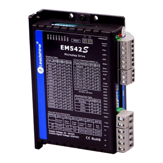
EM542S Digital Stepper Drive User Manual The second 8-bit DIP switch is located on the top (DIP switch selector 2 in figure 2), and used to configure settings of control command filtering time, motor auto-configuration, fault output impedance, pulse active edge, control mode, lock shaft, and self-test as shown below: 7.1 Output Current Configuration (SW1-3) -
Page 13: Micro Step Configuration (Sw5-8)
EM542S Digital Stepper Drive User Manual 7.3 Micro Step Configuration (SW5-8) Each EM542S has 16 micro step settings which can be configured through DIP switch SW5, SW6, SW7, and SW8. See the following table for detail. Micro step Pulses/Rev. (for 1.8° motor) 1600 (default) 3200 6400... -
Page 14: Alarm Output Configuration (Sw12)
EM542S Digital Stepper Drive User Manual 7.6 Alarm Output Configuration (SW12) DIP switch SW12 is used to configure the impedance state of alarm output (fault output). At OFF position (default) the resistance between ALM+ and ALM- is set to low impedance in normal operation, and will change to high impedance when the drive goes into over-voltage or over-current protection. -
Page 15: Sequence Chart Of Control Signals
EM542S Digital Stepper Drive User Manual Controller EM542S PUL+ Step PUL- DIR+ Direction DIR- ENA+ Enable ENA- Control Signal Connector 5-24VDC +Vdc 24-48VDC recommended, leaving rooms for voltage fluctuation ALM+ Fault and back EMF of the motor ALM- Status Signal Power &... -
Page 16: Protection Functions
EM542S Digital Stepper Drive User Manual 11. Protection Functions EM542S incorporates are built with over-voltage and over-current error protections. When it is under error protection, the red LED light will blink for one or two times in a period of 3 seconds. If fault output connection is connected, the impedance mode between ALM+ and ALM- will be changed (See “Fault Output Configuration”... -
Page 17: Troubleshooting
EM542S Digital Stepper Drive User Manual 12. Troubleshooting In the event that your drive doesn’t operate properly, the first step is to identify whether the problem is electrical or mechanical in nature. The next step is to isolate the system component that is causing the problem. As part of this process you may have to disconnect the individual components that make up your system and verify that they operate independently. -
Page 18: Warranty
Twelve Month Warranty Leadshine Technology Co., Ltd. warrants its products against defects in materials and workmanship for a period of 12 months from shipment out of factory. During the warranty period, Leadshine will either, at its option, repair or replace products which proved to be defective. -
Page 19: Contact Us
EM542S Digital Stepper Drive User Manual 14. Contact Us Leadshine Technology Co., Ltd Leadshine America Inc. (Headquarters) Address: Floor 11, Block A3, Nanshan iPark Address: 26050 Towne Centre Dr. 1001 Xueyuan Avenue Foothill Ranch, CA 92610 Nanshan District Shenzhen, Guangdong, 518055...
Need help?
Do you have a question about the EM556S and is the answer not in the manual?
Questions and answers