
Related Manuals for CAME ATS50DGS


Summary of Contents for CAME ATS50DGS
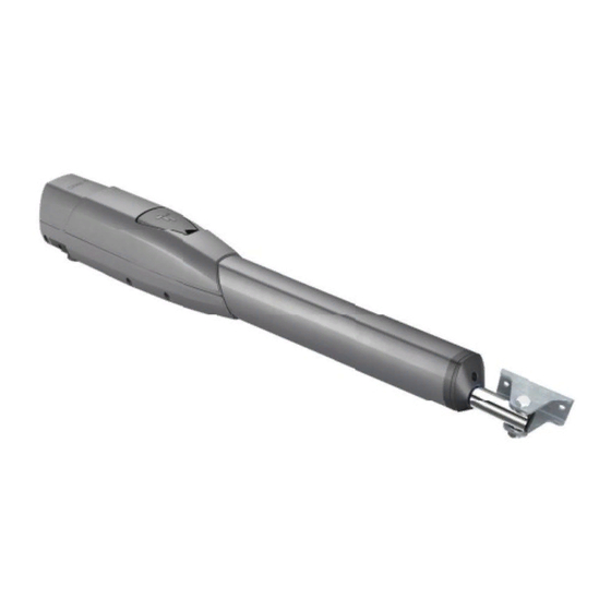
- Page 1 Gearmotor for swing gates FA01561-EN ATS30DGS ATS50DGS ATS30DGR English INSTALLATION MANUAL...
- Page 3 Machinery Directive (2006/42/EC) and with the reference harmonised technical standards are specified in the general CAME product catalogue or on the website www.came.com. • Make sure the mains power supply is disconnected during all installation procedures. • Check that the temperature ranges given are suitable for the installation site. • The appliance must be powered with a voltage corresponding to the value shown on the rating plate.
- Page 4 DISMANTLING AND DISPOSAL CAME S.p.A. employs an Environmental Management System at its premises. This system is certified and compliant with the UNI EN ISO 14001 standard to ensure that the environment is respected and safeguarded. Please continue safeguarding the environment. At CAME we consider it one of the fundamentals of our operating and market strategies.
-
Page 5: Intended Use
ATS30DGS - Irreversible telescopic gearmotor 24 V with encoder for swing gates with Max. C up to 200 mm with leaf up to 3 m and 400 kg. Grey RAL7024. 801MP-0080 ATS50DGS - Irreversible telescopic gearmotor 24 V with encoder for swing gates with Max. C up to 200 mm with leaf up to 5 m and 400 kg. Grey RAL7024. 801MP-0110 ATS30DGR - Irreversible telescopic gearmotor 24 V with encoder for swing gates with max. - Page 6 Size 1320 ATS30DGS ATS30DGR 1550 1050 ATS50DGS Usage limitations MODELS ATS30DGS ATS50DGS ATS30DGR Gate-leaf length (m) Gate-leaf weight (Kg) 1000 For leaves longer than 2.5 m, install an electric lock. Technical data MODELS ATS30DGS ATS50DGS ATS30DGR Motor power supply (V)
-
Page 7: Installation
INSTALLATION The following illustrations are examples only. The space available for fitting the operator and accessories varies depending on the area where it is installed. It is up to the installer to find the most suitable solution. The drawings refer to a gearmotor installed on the left-hand side. Preliminary operations Prepare the junction boxes and corrugated tubes you need for the connections from the junction pit. - Page 8 First determine where the gate bracket needs to be positioned, then where the post bracket needs to be positioned. Respect the values indicated in the table. ≥60 ATS30DGS ATS30DGR Gate-leaf opening (°) Max. C 90° 1220 90° 1290 90° 1300 120° 1300 ATS50DGS Gate-leaf opening (°) Max. C 90° 1030 1430 90° 1030 1510 120° 1030 1460...
-
Page 9: Fastening The Brackets
Fastening the brackets Secure the post bracket with plugs and screws. The holes on the bracket fixing plate allow you to vary the opening angle of the gate leaf. Fasten in place with screws or weld the bracket to the gate. ø... - Page 10 Fastening the gearmotor Lubricate all moving parts on the operator. The self-locking nut must be loosely tightened so as not to affect the movement of the telescopic arm with the gate bracket. ATS30DGR...
-
Page 11: Electrical Connections
ELECTRICAL CONNECTIONS Before working on the control panel, disconnect the mains power supply and remove the batteries, if any. Remove the protective cover to access the terminal board. Control panel Gearmotor delayed while opening Gearmotor delayed while closing 230 V AC - 50-60 HZ power supply input Yellow/green cable M N ENC M N ENC... - Page 12 Determining the end-of-travel points with micro limit switches Rod for determining the opening end-of-travel point Rod for determining the closing end-of-travel point Micro limit switches The micro switches are positioned at the far ends of the travel range. To move the microswitch 10 mm in either direction, turn the rod 20 times. Determining the opening end-of-travel points Perform the operations on both gearmotors.
- Page 13 Determining the closing end-of-travel points Perform the operations on both gearmotors. Release the gearmotor. Manually close the leaf to the desired point. Disconnect the 9-pole terminal board. Connect the multimeter set to check continuity to the Rc-Rc terminals (NC contact); a buzzer will sound on the multimeter. Turn the shaft (C) ANTICLOCKWISE to determine the closing travel end point, until the Rc-Rc contact opens and the multimeter stops buzzing.
- Page 14 First determine where the gate bracket needs to be positioned, then where the post bracket needs to be positioned. Respect the values indicated in the table. Additional bracket (not included) ATS30DGS ATS30DGR Gate-leaf opening (°) 90° ATS50DGS Gate-leaf opening (°) 90° 1030...
- Page 15 Electrical connections Before working on the control panel, disconnect the mains power supply and remove the batteries, if any. Remove the protective cover to access the terminal board. Control panel Gearmotor delayed while opening Gearmotor delayed while closing 230 V AC - 50-60 HZ power supply input Yellow/green cable M1 N1 ENC1 M2 N2 ENC2...
- Page 16 Determining the end-of-travel points with micro limit switches Rod for determining the closing end-of-travel point Rod for determining the opening end-of-travel point Micro limit switches The micro switches are positioned at the far ends of the travel range. To move the microswitch 10 mm in either direction, turn the rod 20 times. Determining the opening end-of-travel points Perform the operations on both gearmotors.
- Page 17 Determining the closing end-of-travel points Perform the operations on both gearmotors. Release the gearmotor. Manually close the leaf to the desired point. Disconnect the 9-pole terminal board. Connect the multimeter set to check continuity to the Ra-Ra terminals (NC contact); a buzzer will sound on the multimeter. Turn the shaft (A) CLOCKWISE to determine the closing travel end point, until the Ra-Ra contact opens and the multimeter stops buzzing.
- Page 18 MCBF Models ATS30AGS-ATS30AGR ATS50AGS-ATS50AGR 2 m - 800 kg 120000 2.5 m - 600 kg 110000 3 m - 400 kg 100000 2 m - 1000 kg 120000 2.5 m - 800 kg 110000 3 m - 600 kg 100000 4 m - 500 kg 85000 5 m - 400 kg...
- Page 20 CAME S.p.A. Via Martiri della Libertà, 15 31030 Dosson di Casier Treviso - Italy Tel. (+39) 0422 4940 Fax (+39) 0422 4941...
- Page 21 FA01359-EN ZL65 INSTALLATION MANUAL English...
- Page 22 fi nal installation to comply with the Machinery Directive (2006/42/EC) and with the reference harmonised technical standards are specifi ed in the general CAME product catalogue or on the website www.came.com. • Check that the temperature ranges given are suitable for the installation site.
-
Page 23: Dismantling And Disposal
• The electrical cables must pass through special pipes, ducts and cable glands in order to guarantee adequate protection against mechanical damage. • The electrical cables must not touch any parts that may overheat during use (such as the motor and transformer). • Before installation, check that the guided part is in good mechanical condition, and that it opens and closes correctly. - Page 24 UNI EN ISO 14001 standard to ensure that the environment is respected and safeguarded. Please continue safeguarding the environment. At CAME we consider it one of the fundamentals of our operating and market strategies. Simply follow these brief disposal guidelines: DISPOSING OF THE PACKAGING The packaging materials (cardboard, plastic, etc.) can be disposed of easily as solid urban waste, separated for recycling.
- Page 25 PRODUCT DATA AND INFORMATION This symbol shows which parts to read carefully. This symbol shows which parts describe safety issues. This symbol shows what to tell users. The measurements, unless otherwise stated, are in millimetres. Description 002ZL65 Control panel for one or two-leaf swing gates, with programming display, on-board radio decoding and self-diagnosing safety devices.
-
Page 26: Description Of Parts
Description of parts Transformer Terminal board for connecting the antenna Line fuse Connector for the UR042 module Power supply terminal board Connector for plug-in radio frequency card (AF) Terminal board for connecting the signalling devices Connector for the R700 or R800 decoding card Terminal boards for gearmotors with encoder RIO CONN card connector Terminal board for connecting control devices... - Page 27 Size Cable types and minimum thicknesses Cable length (m) up to 20 from 20 to 30 Power supply 230 V AC 3G x 1.5 mm² 3G x 2.5 mm² 24 V AC/DC fl ashing beacon 2 x 0.5 mm² 2 x 0.5 mm² TX Photocells 2 x 0.5 mm²...
- Page 28 INSTALLATION Preparing the control panel Separate the parts of the control panel. Drill the pre-marked holes. The diameter of the holes is 20 mm.
- Page 29 Fastening the control panel Drill the fi xing points in the control panel in a protected area. Fasten the base using screws and plugs. Use Phillips round head screws (maximum diameter 6 mm). Insert the cable gland with the corrugated tubes for threading the electrical cables...
-
Page 30: Electrical Connections
ELECTRICAL CONNECTIONS Preparing the electrical cables Connect all wires and cables in compliance with the law. Use cable glands to connect the devices to the control panel. One of these must be used exclusively for the power supply cable. -
Page 31: Power Supply
Power supply Connecting to the mains (120/230 V AC - 50/60 Hz) Power supply output for accessories The output normally delivers 24 V AC. The output delivers 24 V DC when the batteries start operating, if they are installed. 10 11 E 5 Maximum capacity of contacts Device Output... -
Page 32: Command And Control Devices
Command and control devices STOP button (NC contact) Stop the gate and exclude automatic closing. Use a control device to resume movement. If the contact is not used, it must be deactivated during programming. Control device (NO contact) PARTIAL OPENING function PEDESTRIAN OPENING function OPEN ONLY function See function [F8] command 2-3P. -
Page 33: Signalling Devices
Signalling devices During programming, confi gure the type of action that must be performed by the device connected to the output. Flashing beacon It fl ashes when the operator opens and closes. See function [F18] additional light. Additional light It increases the light in the manoeuvring area. See function [F18] additional light. -
Page 34: Safety Devices
Safety devices During programming, confi gure the type of action that must be performed by the device connected to the input. Connect the safety devices to the CX and/or CY inputs. If contacts CX and/or CY are not used, they must be deactivated during programming. DELTA photocells DELTA photocells Standard connection... - Page 35 DXR photocells DXR photocells Standard connection Connection with safety test See function [F5] Safety devices test. 10 TS 2 CX CY 10 TS 2 CX CY 10 11 E 5 10 11 E 5 10 11 OUT 10 11 SY 10 11 OUT 10 11 SY DFWN sensitive edge...
-
Page 36: Getting Started
PROGRAMMING Programming button functions ESC button The ESC button is used to perform the operations described below. Exit the menu Delete the changes Go back to the previous screen < > buttons The <> buttons are used to perform the operations described below. Navigate the menu Increase or decrease values ENTER button... - Page 37 CX input Associate a function with the CX input. The parameter [C3] appears only if the [Automatic closing] function is active CX input OFF (Default) C1 = Reopen while closing (photocells) C2 = Reclose while opening (photocells) C3 = Partial stop Only with [Automatic close] activated.
- Page 38 Command 2-7 Associate a command with the device connected to 2-7. Command 2-7 0 = Step-by-step (default) 1 = Sequential 2 = Open 3 = Close Command 2-3P Associate a command to the connected device on 2-3P. Command 2-3P 0 = Pedestrian opening (Default) Complete opening of M2 only.
- Page 39 Soft start Set a slowdown of a few seconds after each opening and closing command. Soft start OFF (Default) Closing thrust When the leaves reach the closing limit-switch, the operator performs a closing thrust for a few seconds. Closing thrust OFF (Default) 1 = Minimum thrust 2 = Medium thrust...
- Page 40 Automatic closing after either partial or pedestrian opening. Set the time before automatic closure is activated, after a partial opening command has been performed or after the photocells have caused a partial stop [C3]. The function does not work if any of the safety devices are triggered when an obstacle is detected, or after a complete stop, or during a power outage.
- Page 41 Calibration speed Set the speed during travel self-learning (percentage of maximum speed). Calibration speed 20% to 60% (Default 50%) Travel sensitivity Adjust the obstruction detection sensitivity during boom travel (percent). Travel sensitivity 10% to 100% (Default 100%) 10% = minimum thrust and high obstruction sensitivity 100% = maximum thrust and low obstruction sensitivity...
- Page 42 Opening slowdown point for M2 Set the opening slowdown starting point for M2 (percentage of the total travel). Opening slowdown point 1% to 60% (Default 25%) Closing slowdown point for M2 Set the closing slowdown starting point for M2 (percentage of the total travel). Closing slowdown point 1% to 60% (Default 25%) Opening approach point for M2...
-
Page 43: Communication Speed
Peripheral number Assign a unique identifi cation code (CRP address) to the control board. It is used where there are multiple operators connected to the same communication BUS with CRP protocol. Peripheral number from 1 to 255 Communication speed Set the communication speed of the remote connection system. Communication speed 0 = 1200 bps 1 = 2400 bps... - Page 44 Choose the function to be assigned to the user. Press ENTER to confi rm. Send the code from the control device. Repeat the procedure to add other users. Download the LIST OF REGISTERED USERS form from the docs.came.com portal by typing in L20180423.
- Page 45 Remove user Remove one of the registered users. Remove user OFF (Default) Use the arrows to choose the number associated with the user you want to remove. No. 1 > 250 Alternatively, the control device associated with the user you want to remove can be activated.
- Page 46 Motor test Check the gate leaves open in the right direction. With the function active, in single-leaf gates, the > button opens the gate with the gearmotor connected to M2-N2; With the function active, in two-leaf gates, the > button opens the gate with the gearmotor connected to M2-N2; the < button opens the gate with the gearmotor connected to M1-N1.
-
Page 47: Error And Warning Messages
ERROR AND WARNING MESSAGES The travel calibration was interrupted to activate the STOP button. Adjustment error Encoder failure error Service test failure error Operating time error Obstacle detected during closing Obstacle detected during opening Maximum number of obstacles Serial communication error Incompatible remote control Wireless system communication error Wireless system not confi... -
Page 48: Final Operations
FINAL OPERATIONS Before closing up the casing, check that the cable inlets are sealed to stop insects getting in and to prevent damp. - Page 52 CAME S.p.A. Via Martiri della Libertà, 15 31030 Dosson di Casier Treviso - Italy Tel. (+39) 0422 4940 Fax (+39) 0422 4941...
Need help?
Do you have a question about the ATS50DGS and is the answer not in the manual?
Questions and answers