
Related Manuals for CAME ATS30AGS


Summary of Contents for CAME ATS30AGS
- Page 1 Gearmotor for swing gates FA01337-EN ATS30AGS ATS50AGS ATS30AGR ATS50AGR English INSTALLATION MANUAL...
- Page 3 Machinery Directive (2006/42/EC) and with the reference harmonised technical standards are specified in the general CAME product catalogue or on the website www.came.com. • Make sure the mains power supply is disconnected during all installation procedures. • Check that the temperature ranges given are suitable for the installation site. • Do not install the operator on surfaces that could yield and bend.
- Page 4 DISMANTLING AND DISPOSAL CAME S.p.A. employs an Environmental Management System at its premises. This system is certified and compliant with the UNI EN ISO 14001 standard to ensure that the environment is respected and safeguarded. Please continue safeguarding the environment. At CAME we consider it one of the fundamentals of our operating and market strategies.
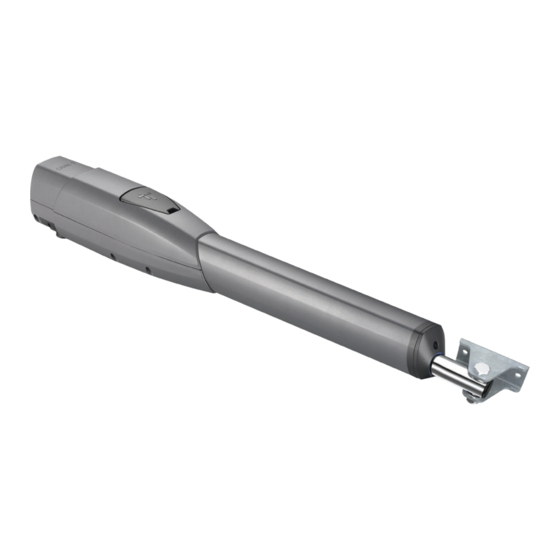
- Page 5 Description 801MP-0050 ATS30AGS - Irreversible telescopic gearmotor 230 V for swing gates with Max. C 200 mm with leaf up to 3 m and 400 kg. Grey RAL7024. 801MP-0060 ATS50AGS - Irreversible telescopic gearmotor 230 V for swing gates with Max. C 200 mm with leaf up to 5 m and 400 kg. Grey RAL7024.
- Page 6 Door to access the end-of-travel adjustment screws Door to access the release mechanism M12,1 UNI6592 Sheath connector Post bracket Release key Release cord* M12 UNI7474 Cutting hazard labels *ATS30AGR *ATS50AGR M8x35 UNI5737 M8 UNI5588 Size 1320 ATS30AGS ATS30AGR 1550 ATS50AGS 1050 ATS50AGR...
- Page 7 Usage limitations MODELS ATS30AGS ATS50AGS Gate-leaf length (m) Gate-leaf weight (Kg) 1000 MODELS ATS30AGR ATS50AGR Gate-leaf length (m) Gate-leaf weight (Kg) 1000 For leaves longer than 2.5 m, install an electric lock. Technical data MODELS ATS30AGS ATS50AGS ATS30AGR ATS50AGR Power supply (V - 50/60 Hz)
-
Page 8: Installation
INSTALLATION The following illustrations are examples only. The space available for fitting the operator and accessories varies depending on the area where it is installed. It is up to the installer to find the most suitable solution. The drawings refer to a gearmotor installed on the left-hand side. Preliminary operations Prepare the junction boxes and corrugated tubes you need for the connections from the junction pit. - Page 9 Manually open the gate leaf to 90° or 120°. First determine where the gate bracket needs to be positioned, then where the post bracket needs to be positioned. Respect the values indicated in the table. ≥60 ATS30AGS ATS30AGR Gate-leaf opening (°) Max. C 90°...
- Page 10 Fastening the brackets Secure the post bracket with plugs and screws. If the post is made of metal, the post bracket must be welded to it. The holes on the bracket fixing plate allow you to vary the opening angle of the gate leaf. Fasten in place with screws or weld the bracket to the gate.
- Page 11 Fastening the gearmotor Lubricate all moving parts on the operator. The self-locking nut must be loosely tightened so as not to affect the movement of the telescopic arm with the gate bracket. ATS30AGR ATS50AGR...
- Page 12 ELECTRICAL CONNECTIONS Before working on the control panel, disconnect the mains power supply and remove the batteries, if any. Remove the protective cover to access the terminal board. Control panel Gearmotor delayed while opening Gearmotor delayed while closing 230 V AC - 50-60 HZ power supply input Yellow/green cable...
- Page 13 Determining the end-of-travel points with micro limit switches Rod for determining the opening end-of-travel point Rod for determining the closing end-of-travel point Micro limit switches The micro switches are positioned at the far ends of the travel range. To move the microswitch 10 mm in either direction, turn the rod 20 times. Determining the opening end-of-travel points Release the gearmotor.
- Page 14 Close the gate manually. First determine where the gate bracket needs to be positioned, then where the post bracket needs to be positioned. Respect the values indicated in the table. Additional bracket (not included) ATS30AGS ATS30AGR Gate-leaf opening (°) 90°...
- Page 15 Electrical connections Before working on the control panel, disconnect the mains power supply and remove the batteries, if any. Remove the protective cover to access the terminal board. Control panel Gearmotor delayed while opening Gearmotor delayed while closing 230 V AC - 50-60 HZ power supply input Yellow/green cable...
- Page 16 Determining the end-of-travel points with micro limit switches Rod for determining the closing end-of-travel point Rod for determining the opening end-of-travel point Determining the opening end-of-travel points Release the gearmotor. Open the gate manually. Send an opening command. At the same time, turn the rod for determining the opening end-of-travel point ANTICLOCKWISE until the gearmotor stops. Leave the rod nut loose to determine the end-of-travel points.
-
Page 17: Final Operations
FINAL OPERATIONS... - Page 18 MCBF Models ATS30AGS-ATS30AGR ATS50AGS-ATS50AGR 2 m - 800 kg 120000 2.5 m - 600 kg 110000 3 m - 400 kg 100000 2 m - 1000 kg 120000 2.5 m - 800 kg 110000 3 m - 600 kg 100000...
-
Page 19: Control Panel
CONTROL PANEL FA00679-EN FOR 120 V OR 230 V GEARMOTORS ZF1N110 / ZF1N EN English INSTALLATION MANUAL... -
Page 20: Intended Use
All connections and links are rapid-fuse protected. Intended use The ZF1N110 / ZF1N control panel is designed to control CAME gearmotors for swing gates in private homes and apartment buildings. Any installation and/or use other than that specifi ed in this manual is forbidden. -
Page 21: Description Of Parts
Description of parts ① Transformer ② Line fuse ③ Power supply terminals ④ Transformer terminal boards ⑤ Control-board fuse ⑥ Terminals for control and safety devices ⑦ Alert LED ⑧ Antenna terminal ⑨ DIP-SWITCH ⑩ AF card connector ⑪ Automatic closing trimmer ⑫ ... -
Page 22: Tools And Materials
Tools and materials Make sure you have all the tools and materials you will need for installing in total safety and in compliance with applicable regulations. The fi gure shows some of the equipment installers will need. Cable types and minimum thicknesses cable length Connection <... -
Page 23: Input Voltage
INSTALLATION Fastening the control panel Fasten the control panel in a protected area using suitable screws and dowels . Only use 6 x 70 mm cylinder-head screws. Drill through the pre-drilled holes (18 and 20 mm) under the control panel's base . ⚠ ... - Page 24 Connecting the gearmotors Gearmotor (M1) 120 V AC* or 230 V AC, Gearmotor (M2) 120 V AC* or 230 V AC, delayed when opening. delayed when closing. FERNI FERNI FAST FAST KRONO KRONO * 120 V AC version if available U V W X Y E Motor's torque limiter To vary the motor torque, move the faston as shown to one of the four positions: 1 min ÷...
- Page 25 Command and control devices TS 5 C1 7 2 1 11 10 ES ES STOP button (NC contact). For stopping the gate while excluding automatic closing. To resume movement press the control button or use another control device. If unused, short-circuit the contact. OPEN-CLOSE-INVERT function (step-step) from control device (NO contact).
- Page 26 Safety devices Photocells Input for safety devices such as photocells. Reopening during closing. When the gate is closing, opening the contact triggers the inversion of movement until the gate is fully open again; If the photocells are left unused, short-circuit contact 2-C1. TS 5 C1 7 2 1 11 10 ES ES TS 5 C1 7 2 1 11 10 ES ES - NO C...
-
Page 27: Functions And Settings
FUNCTIONS AND SETTINGS Functions DIP-SWITCH Description of functions AUTOMATIC CLOSING Automatic closing active (1 OFF - Deactivated) OPEN-STOP-CLOSE-STOP OPEN-STOP-CLOSE-STOP (sequential) function from control device (NO contact) and from radio transmitter fitted with AF card. OPEN-CLOSE-INVERT OPEN-CLOSE-INVERT (step-step) function from control device (NO contact) and from radio transmitter fitted with AF card. -
Page 28: Preliminary Operations
MANAGING USERS BY RADIO CONTROL Preliminary operations Connect the RG58 cable antenna cable to the corresponding terminals . Fit the AF card into the control board connector . Before fi tting the AF card, you MUST CUT OFF THE MAIN POWER SUPPLY and, remove any emergency bat- teries. -
Page 29: Deleting A Single User
Deleting a single user Set DIP-switch 4 to ON. Keep pressed the PROG button on the control board. The programming LED fl ashes. Within fi ve seconds, press the button on the transmitter of the user you wish to delete. The LED will fl ash quickly for one second to signal that the user has been deleted, and then it will switch off . -
Page 30: Dismantling And Disposal
These must therefore be disposed of by authorized, certifi ed professional services. DISPOSE OF RESPONSIBLY! REFERENCE REGULATIONS CAME SpA declares that this product complies with the current directives at the time it is manufactured. CAME S.p.A. Via Martiri Della Libertà, 15 31030 Dosson di Casier - Treviso - Italy tel.
Need help?
Do you have a question about the ATS30AGS and is the answer not in the manual?
Questions and answers